EP1157718A2 - Commande de cycle de soupape linéaire à gaz, soupape d'arrêt et auto-test - Google Patents
Commande de cycle de soupape linéaire à gaz, soupape d'arrêt et auto-test Download PDFInfo
- Publication number
- EP1157718A2 EP1157718A2 EP01112020A EP01112020A EP1157718A2 EP 1157718 A2 EP1157718 A2 EP 1157718A2 EP 01112020 A EP01112020 A EP 01112020A EP 01112020 A EP01112020 A EP 01112020A EP 1157718 A2 EP1157718 A2 EP 1157718A2
- Authority
- EP
- European Patent Office
- Prior art keywords
- port
- molecular sieve
- slide block
- slide
- linear valve
- Prior art date
- Legal status (The legal status is an assumption and is not a legal conclusion. Google has not performed a legal analysis and makes no representation as to the accuracy of the status listed.)
- Granted
Links
- 238000012360 testing method Methods 0.000 title description 2
- 239000002808 molecular sieve Substances 0.000 claims abstract description 26
- URGAHOPLAPQHLN-UHFFFAOYSA-N sodium aluminosilicate Chemical compound [Na+].[Al+3].[O-][Si]([O-])=O.[O-][Si]([O-])=O URGAHOPLAPQHLN-UHFFFAOYSA-N 0.000 claims abstract description 26
- 238000004891 communication Methods 0.000 claims abstract description 6
- 239000007789 gas Substances 0.000 claims description 27
- QVGXLLKOCUKJST-UHFFFAOYSA-N atomic oxygen Chemical compound [O] QVGXLLKOCUKJST-UHFFFAOYSA-N 0.000 claims description 16
- 239000001301 oxygen Substances 0.000 claims description 16
- 229910052760 oxygen Inorganic materials 0.000 claims description 16
- 238000000034 method Methods 0.000 claims description 8
- 238000012544 monitoring process Methods 0.000 claims description 6
- 230000003287 optical effect Effects 0.000 claims description 3
- 238000001179 sorption measurement Methods 0.000 claims description 3
- IJGRMHOSHXDMSA-UHFFFAOYSA-N Atomic nitrogen Chemical compound N#N IJGRMHOSHXDMSA-UHFFFAOYSA-N 0.000 description 8
- 230000008569 process Effects 0.000 description 6
- 229910052757 nitrogen Inorganic materials 0.000 description 4
- 230000015556 catabolic process Effects 0.000 description 3
- 238000006731 degradation reaction Methods 0.000 description 3
- 230000008859 change Effects 0.000 description 2
- 238000010586 diagram Methods 0.000 description 2
- 239000006260 foam Substances 0.000 description 2
- 230000036541 health Effects 0.000 description 2
- 238000013022 venting Methods 0.000 description 2
- 230000000903 blocking effect Effects 0.000 description 1
- 230000001143 conditioned effect Effects 0.000 description 1
- 238000001514 detection method Methods 0.000 description 1
- 230000000694 effects Effects 0.000 description 1
- 238000005516 engineering process Methods 0.000 description 1
- 239000011261 inert gas Substances 0.000 description 1
- 238000012423 maintenance Methods 0.000 description 1
- 230000013011 mating Effects 0.000 description 1
- 238000012986 modification Methods 0.000 description 1
- 230000004048 modification Effects 0.000 description 1
- 238000007789 sealing Methods 0.000 description 1
- 239000007787 solid Substances 0.000 description 1
- 238000006467 substitution reaction Methods 0.000 description 1
- 230000007704 transition Effects 0.000 description 1
Images


Classifications
-
- F—MECHANICAL ENGINEERING; LIGHTING; HEATING; WEAPONS; BLASTING
- F16—ENGINEERING ELEMENTS AND UNITS; GENERAL MEASURES FOR PRODUCING AND MAINTAINING EFFECTIVE FUNCTIONING OF MACHINES OR INSTALLATIONS; THERMAL INSULATION IN GENERAL
- F16K—VALVES; TAPS; COCKS; ACTUATING-FLOATS; DEVICES FOR VENTING OR AERATING
- F16K37/00—Special means in or on valves or other cut-off apparatus for indicating or recording operation thereof, or for enabling an alarm to be given
-
- B—PERFORMING OPERATIONS; TRANSPORTING
- B01—PHYSICAL OR CHEMICAL PROCESSES OR APPARATUS IN GENERAL
- B01D—SEPARATION
- B01D53/00—Separation of gases or vapours; Recovering vapours of volatile solvents from gases; Chemical or biological purification of waste gases, e.g. engine exhaust gases, smoke, fumes, flue gases, aerosols
- B01D53/02—Separation of gases or vapours; Recovering vapours of volatile solvents from gases; Chemical or biological purification of waste gases, e.g. engine exhaust gases, smoke, fumes, flue gases, aerosols by adsorption, e.g. preparative gas chromatography
- B01D53/04—Separation of gases or vapours; Recovering vapours of volatile solvents from gases; Chemical or biological purification of waste gases, e.g. engine exhaust gases, smoke, fumes, flue gases, aerosols by adsorption, e.g. preparative gas chromatography with stationary adsorbents
- B01D53/0407—Constructional details of adsorbing systems
- B01D53/0446—Means for feeding or distributing gases
-
- F—MECHANICAL ENGINEERING; LIGHTING; HEATING; WEAPONS; BLASTING
- F16—ENGINEERING ELEMENTS AND UNITS; GENERAL MEASURES FOR PRODUCING AND MAINTAINING EFFECTIVE FUNCTIONING OF MACHINES OR INSTALLATIONS; THERMAL INSULATION IN GENERAL
- F16K—VALVES; TAPS; COCKS; ACTUATING-FLOATS; DEVICES FOR VENTING OR AERATING
- F16K11/00—Multiple-way valves, e.g. mixing valves; Pipe fittings incorporating such valves
- F16K11/02—Multiple-way valves, e.g. mixing valves; Pipe fittings incorporating such valves with all movable sealing faces moving as one unit
- F16K11/06—Multiple-way valves, e.g. mixing valves; Pipe fittings incorporating such valves with all movable sealing faces moving as one unit comprising only sliding valves, i.e. sliding closure elements
- F16K11/065—Multiple-way valves, e.g. mixing valves; Pipe fittings incorporating such valves with all movable sealing faces moving as one unit comprising only sliding valves, i.e. sliding closure elements with linearly sliding closure members
- F16K11/0655—Multiple-way valves, e.g. mixing valves; Pipe fittings incorporating such valves with all movable sealing faces moving as one unit comprising only sliding valves, i.e. sliding closure elements with linearly sliding closure members with flat slides
-
- F—MECHANICAL ENGINEERING; LIGHTING; HEATING; WEAPONS; BLASTING
- F16—ENGINEERING ELEMENTS AND UNITS; GENERAL MEASURES FOR PRODUCING AND MAINTAINING EFFECTIVE FUNCTIONING OF MACHINES OR INSTALLATIONS; THERMAL INSULATION IN GENERAL
- F16K—VALVES; TAPS; COCKS; ACTUATING-FLOATS; DEVICES FOR VENTING OR AERATING
- F16K37/00—Special means in or on valves or other cut-off apparatus for indicating or recording operation thereof, or for enabling an alarm to be given
- F16K37/0025—Electrical or magnetic means
- F16K37/0041—Electrical or magnetic means for measuring valve parameters
-
- B—PERFORMING OPERATIONS; TRANSPORTING
- B01—PHYSICAL OR CHEMICAL PROCESSES OR APPARATUS IN GENERAL
- B01D—SEPARATION
- B01D2256/00—Main component in the product gas stream after treatment
- B01D2256/12—Oxygen
-
- B—PERFORMING OPERATIONS; TRANSPORTING
- B01—PHYSICAL OR CHEMICAL PROCESSES OR APPARATUS IN GENERAL
- B01D—SEPARATION
- B01D2259/00—Type of treatment
- B01D2259/40—Further details for adsorption processes and devices
- B01D2259/40003—Methods relating to valve switching
-
- B—PERFORMING OPERATIONS; TRANSPORTING
- B01—PHYSICAL OR CHEMICAL PROCESSES OR APPARATUS IN GENERAL
- B01D—SEPARATION
- B01D2259/00—Type of treatment
- B01D2259/40—Further details for adsorption processes and devices
- B01D2259/40007—Controlling pressure or temperature swing adsorption
- B01D2259/40009—Controlling pressure or temperature swing adsorption using sensors or gas analysers
-
- B—PERFORMING OPERATIONS; TRANSPORTING
- B01—PHYSICAL OR CHEMICAL PROCESSES OR APPARATUS IN GENERAL
- B01D—SEPARATION
- B01D2259/00—Type of treatment
- B01D2259/40—Further details for adsorption processes and devices
- B01D2259/402—Further details for adsorption processes and devices using two beds
-
- B—PERFORMING OPERATIONS; TRANSPORTING
- B01—PHYSICAL OR CHEMICAL PROCESSES OR APPARATUS IN GENERAL
- B01D—SEPARATION
- B01D53/00—Separation of gases or vapours; Recovering vapours of volatile solvents from gases; Chemical or biological purification of waste gases, e.g. engine exhaust gases, smoke, fumes, flue gases, aerosols
- B01D53/02—Separation of gases or vapours; Recovering vapours of volatile solvents from gases; Chemical or biological purification of waste gases, e.g. engine exhaust gases, smoke, fumes, flue gases, aerosols by adsorption, e.g. preparative gas chromatography
- B01D53/04—Separation of gases or vapours; Recovering vapours of volatile solvents from gases; Chemical or biological purification of waste gases, e.g. engine exhaust gases, smoke, fumes, flue gases, aerosols by adsorption, e.g. preparative gas chromatography with stationary adsorbents
- B01D53/047—Pressure swing adsorption
Definitions
- the present invention relates generally to gas valves, and more particularly, to a linear gas valve in which the position of a slide block housed therein can be detected.
- On Board Inert Gas Generating Systems (OBIGGS) or On Board Oxygen Generating Systems (OBOGS) utilize molecular sieve by employing a pressure swing adsorption (PSA) process that has been used for many years to generate either nitrogen or oxygen product sequentially, respectively.
- PSA pressure swing adsorption
- This PSA technology uses conditioned engine bleed air fed through the valve to pressurize molecular sieve contained in each of a number of canisters. After a predetermined period of time, a valve changes state, venting the one pressurized canister and then pressurizing the next canister.
- Previous PSA systems have been controlled by a rotary valve which is controlled by a valve and driven by a fixed or variable speed motor.
- Recent PSA systems utilize a linear 4-way slide valve, which connects, input air with one canister, while connecting a vent port with another canister.
- the valve changes state, which connects the vent port with the first canister and simultaneously connecting the second canister with the input air.
- the linear valve used on typical PSA systems is pneumatically operated using control pilot gas from miniature pilot solenoid valves and are opened and closed using solid state electronics which are housed in an EMI shielded enclosure.
- the pilot solenoids provide gas pressure to two gas cylinders, which are connected to a sliding block.
- the block slides across a mating plate with three openings or ports.
- the ports are constructed in a straight line.
- the outer ports are equal-distance from center port.
- the sliding block has an undercut, which acts as a flow path.
- the flow path is sized to connect two of the three ports at any one point in time.
- a controller is set to open and close the miniature pilot valves at a predetermined time or "cycle time".
- the PSA device functions by forcing the undesired gas molecules into "sites" in the molecular sieve.
- the cycle time of the PSA process is largely determined by what purity is desired of the product gas.
- the slide block is controlled to provide the air to the desired canister and simultaneously vent the other canister. If the slide block slows down the resulting purity changes.
- Airborne OBOGS systems usually have oxygen monitors to detect oxygen purity degradation and alarm the operator/pilot of a failure to produce desired oxygen. There are a number of internal and external conditions which result in poor oxygen. One internal condition which would cause poor purity would be a slide valve, which did not change state or changed state slower than desired. Airborne OBIGGS systems do not have nitrogen monitors. Some systems use an oxygen monitor and infer the nitrogen purity from the amount of residual oxygen in the product system. Nitrogen product purity is affected in the same manner as oxygen product purity if the slide valve fails to operate properly. External conditions which cause oxygen purity degradation include ambient temperature, below normal operating pressure, sieve degradation, moisture, etc.
- the PSA process handles moisture entrained in the air during normal operation. If moisture enters the system through the air system, when the PSA process is not operating, the result is permanent damage to the molecular sieve. Damaged sieve does not separate air.
- Many OBOGS and OBIGGS systems have separate shut-off valves which prevent the entrance of air into the molecular sieve beds when the system is not operating. Thus, a need exists in the art for a linear valve having a slide block in which the current position of the slide block can be detected. Another need exists for a linear valve in which the separate shut-off valve is eliminated.
- an object of the present invention to provide a linear valve and control system in which the location of the slide block is monitored to trouble shoot performance problems before they occur.
- Another object of the present invention is to provide a linear valve having a slide block in which the position is monitored by a sensing device.
- Another object of the present invention is to provide a linear valve in which a shutoff valve is eliminated between the linear valve and an air source.
- the present invention relates to detecting the state of a slide block positioned in a linear valve and using the position of the slide block to predict the health of a linear valve and provide information to a controller/monitor. An operator is provided with information before failure occurrence to allow preventative maintenance of the linear valve.
- the linear valve is constructed with two canister ports and a vent port.
- the slide block can be constructed to block the two canister ports and vent port simultaneously.
- the system can control the position of the block, when provided with position information, hence, using the slide block as a shutoff valve.
- the typical slide valve can be used as an integral slide shutoff valve, reducing system complexity and reducing system weight, which is critical to airborne applications.
- a control system for controlling a gas generating system including at least two molecular sieve beds.
- a linear valve has a housing including an inlet connected to the gas generating system and a first port connected to a first of the at least two molecular sieve beds, a second port for exhaust, and a third port connected to a second of the at least two molecular sieve beds.
- the inlet, the first, second and third ports are all in communication with a slide chamber in the housing.
- a slide block is positioned in the slide chamber.
- a push-pull device is mounted to the housing for moving the slide block in a first direction and in a second direction.
- a sensor is positioned at opposite ends of the slide chamber for sensing the position of the slide block in the slide chamber.
- a controller is provided for receiving information from the sensing device and for controlling the push-pull device.
- a linear valve including a housing.
- the housing includes an inlet connected to a gas generating system and a first port connected to a first of at least two molecular sieve beds, a second port for exhaust, and a third port connected to a second of the at least two molecular sieve beds, with the inlet, the first, second and third ports all in communication with a slide chamber in the housing with a slide block positioned in the slide chamber.
- a push-pull device is mounted to the housing for moving the slide block in a first direction and in a second direction.
- a sensor is positioned at opposite ends of the slide chamber for sensing the position of the slide block in the slide chamber.
- a method of monitoring an operational status of a linear valve including detecting when a linear slide block is in one of at least two positions, determining at least one of slew rate, full length stroke and uneven stroke and alerting a user if one of the slew rate, full length stroke and uneven stroke exceeds a predetermined value.
- a linear slide valve system includes a linear slide valve assembly 15 and a controller/monitor 30 according to the present invention.
- Linear valve assembly 15 includes a pair of solenoid valves 40, 42 mounted on opposite ends of a housing 20.
- the housing 20 includes an inlet 50 on one side of the housing 20, a first port 52, second port 54 and a third port 56, all on an opposite side of the housing 20.
- the ports 52, 54, 56 are provided in the base plate 48. Ports 52 and 56 are equally spaced from the central port 54.
- a slide block 60 includes a flat surface 62 sliding on an upper surface 64 of the plate 48.
- the inlet 50 is spaced from the slide block 60 and the slide block 60 is of sufficient length to cover either ports 52, 54 or ports 54, 56.
- the solenoids 40, 42 are 3-way solenoids of the type known in the art and are utilized in a preferred embodiment of the invention. Other control means, solenoid, air or otherwise can be used without departing from the spirit and scope of the invention.
- the slide block 60 is driven in a first direction by solenoid valve 40 and in an opposite direction or second direction by solenoid valve 42.
- Rods 44 and 46 are attached to solenoid valves 40, 42 and to the sliding block to move the sliding block in opposite directions.
- Proximity switches 70, 72 are mounted on opposite ends of housing 20.
- On opposite sides of slide block 60 are mounted a pair of magnets 80, 82 which when brought into proximity with switches 70, 72, respectively, a signal is sent to the controller/monitor 30 as will be described in greater detail below.
- the slide block 60 is shown in a first position blocking ports 52 and 54. In this manner, inlet 50 is in communication with port 56 to bed # 2. In this first position, bed #1 can exhaust through the port 52 through the slide block 60 into the exhaust port 54 while air is provided from the inlet 50 through the port 56 to bed #2.
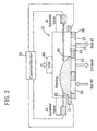
- Figure 2 is similar to Figure 1 except that the slide block is depicted in a second position. In this second position, bed #2 can exhaust through the port 56 and through the slide block 60 into the exhaust port 54 while air is provided from the inlet 50 through the port 52 to bed #1.
- a spring (not shown) is used between the piston and the slide block 60. Closed cell foam has also been used.
- the valve located in Figure 2 does not have a spring or foam. Instead the valve has tight tolerances with the assembly to maintain position of the slide valve. The valve will become seal tight under operating pressures.
- FIG 3 is similar to the embodiment depicted in Figures 1 and 2 except that instead of solenoid valves 40, 42, a pair of air cylinders 140, 142 are used to move a driving member 150 in a first and second direction.
- the driving member 150 is an elongated cylindrically shaped member having two intermediate shoulder members 152, 154 and two piston heads 162, 164. The two intermediate shoulders are partially positioned in slots 166, 168, respectively for engagement with a sliding block 160.
- the sliding block 160 includes magnets 80, 82 mounted in the lower surface 64.
- a pair of sensors 70, 72 are mounted in the plate 48 at opposite ends of a slide block chamber 170. Formed between the piston heads 160, 162 and plate 48 is the slide block chamber 170.
- An inlet (not shown) is centered in the housing just above the exhaust port.
- housing 120 At opposite ends of housing 120 are opposite cylindrical bores 180, 182, in which piston heads 160, 162 slide in a reciprocal fashion, respectively. Threaded on opposite surfaces of housing 120 are threads and onto each of the threads are caps 190, 192 to seal off and form a first cylinder 200 and a second cylinder 202 in which piston heads 160, 162 slide respectively.
- Poppets 210, 212 are located in threaded members 190, 192.
- the driving member 150 is moved in opposite directions as follows.
- poppet 210 would be opened and the cylinder 200 pressurized while poppet 212 would also be opened allowing the cylinder to be vented thereby moving the driving member to the right with the cylinder 202 being vented.
- Figure 3 also best depicts an undercut 169 through the slide block 160 which permits flow between ports 52, 54 while sealing these ports from the slide chamber 170.
- proximity sensors and magnetic sensors have been described, it should be understood that other sensors could be used in the present invention in any of the embodiments described herein.
- Optical sensors have become very popular recently with infra red and laser. These devices can be very precise. These devices can detect the range of travel as well as the limits of travel. The exact location of the sliding block 60, 160 could be known at all times.
- Pressure transducers are commonly used in testing for such information as cycle rates and slide valve operation by monitoring the cylinder pressure. In conjunction with a strip chart, the operating pressure can be determined pretty accurately. This device can be used to determine the approximate location of the slide block (will not locate precisely).
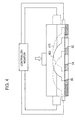
- the slide valve depicted in Figure 4 is similar to the linear slide valves depicted in Figures 1-3 except that the slide chamber 470 has greater length to enable a slide block 460 to be able to simultaneously cover ports 52, 54, 56.
- the sensors are located in the same position as those in Figure 1 with the possible addition of another located centered on the slides of the slide block. This would enable the detection of the slide block in the shut off position.
- the shut-off valve 600 ( Figure 6) can be eliminated.
- the slide chamber 470 depicted in Figure 4 there is greater spacing between the ports 52 and 56 and ends of the slide chamber to allow the slide block 460 to move to the first and second positions depicted in dashed lines in Figure 4.
- FIG. 5 depicts a schematic for operating the linear slide valve depicted in Figure 3.
- the proximity switches 70, 72 are depicted as connected to the controller/monitor 30.
- Three way valves 500, 502 are also each connected to the controller/monitor 30 and are pneumatically connected to the air cylinders 200, 202.
- valve 500 is in a first position inlet air is introduced into the cylinder 202, thereby forcing the piston 164 to change position which triggers the proximity switch 70 to open and the proximity switch 72 to close.
- One way of monitoring the health of the slide valve 15 might be as follows: The controller/monitor commands the slide valve 15 to switch to the opposite of its two positions.
- a timer in the controller/monitor 30 is started.
- the controller/monitor 30 receives the signal from the sensor 70, 72 that the slide block 60 has reached the opposite position, the timer is stopped.
- the length of time elapsed is a measure of the transition time for the valve 15.
- the controller/monitor 30 can detect conditions that have effects on the travel time of the valve 15 such as input air pressure and temperature. Comparing this time to an acceptable time (for the known input pressure and temperature conditions) provides a measure of the performance of the valve.
- a simple display can show instantaneous cycle rate, which could be monitored or a signal would light when cycles rate become out of tolerance.
- the controller/monitor 30 would be used to control the position of the slide block 60 from the location information supplied by the sensors 70, 72. It should now be understood that a linear valve and control system has been described in which the location of the slide block is monitored to troubleshoot performance before they occur. It should also be apparent that a linear valve has been described which eliminates the shut-off valve.
Landscapes
- Engineering & Computer Science (AREA)
- General Engineering & Computer Science (AREA)
- Mechanical Engineering (AREA)
- Chemical & Material Sciences (AREA)
- Analytical Chemistry (AREA)
- General Chemical & Material Sciences (AREA)
- Oil, Petroleum & Natural Gas (AREA)
- Chemical Kinetics & Catalysis (AREA)
- Indication Of The Valve Opening Or Closing Status (AREA)
- Multiple-Way Valves (AREA)
- Separation Of Gases By Adsorption (AREA)
- Respiratory Apparatuses And Protective Means (AREA)
- Magnetically Actuated Valves (AREA)
- Sampling And Sample Adjustment (AREA)
- Feeding And Controlling Fuel (AREA)
- Control Of Combustion (AREA)
- Fluid-Driven Valves (AREA)
Applications Claiming Priority (2)
| Application Number | Priority Date | Filing Date | Title |
|---|---|---|---|
| US09/576,050 US6409807B1 (en) | 2000-05-23 | 2000-05-23 | Linear gas valve cycle control, shut-off-valve and self test |
| US576050 | 2000-05-23 |
Publications (3)
| Publication Number | Publication Date |
|---|---|
| EP1157718A2 true EP1157718A2 (fr) | 2001-11-28 |
| EP1157718A3 EP1157718A3 (fr) | 2002-06-19 |
| EP1157718B1 EP1157718B1 (fr) | 2004-07-28 |
Family
ID=24302761
Family Applications (1)
| Application Number | Title | Priority Date | Filing Date |
|---|---|---|---|
| EP01112020A Expired - Lifetime EP1157718B1 (fr) | 2000-05-23 | 2001-05-23 | Commande de cycle de soupape linéaire à gaz, soupape d'arrêt et auto-test |
Country Status (7)
| Country | Link |
|---|---|
| US (1) | US6409807B1 (fr) |
| EP (1) | EP1157718B1 (fr) |
| JP (1) | JP4730682B2 (fr) |
| KR (2) | KR100893096B1 (fr) |
| AT (1) | ATE271897T1 (fr) |
| CA (1) | CA2348336C (fr) |
| DE (1) | DE60104479T2 (fr) |
Cited By (3)
| Publication number | Priority date | Publication date | Assignee | Title |
|---|---|---|---|---|
| EP1374972A1 (fr) * | 2002-06-27 | 2004-01-02 | Litton Systems, Inc. | Restriction variable du débit de l'air d'admission pour le contrôle de la composition du gaz produit d'une unité PSA |
| FR2880328A1 (fr) * | 2005-01-06 | 2006-07-07 | Air Liquide | Procede et systeme de verification du bon fonctionnement d'un equipement embarque de production d'oxygene pour aeronef |
| US7637280B2 (en) | 2002-10-03 | 2009-12-29 | L'air Liquide - Societe Anonyme A Directoire Et Conseil De Surveillance Pour L'etude Et L'exploitation Des Procedes George Claude | Dual-inlet selective flow regulating valve |
Families Citing this family (13)
| Publication number | Priority date | Publication date | Assignee | Title |
|---|---|---|---|---|
| US7036521B2 (en) * | 2003-04-27 | 2006-05-02 | Carleton Life Support Systems, Inc. | Air conserving slide valve |
| US7445660B2 (en) | 2005-04-27 | 2008-11-04 | Carleton Life Support Systems, Inc. | Method for operating gas generators in tandem |
| JP2009299762A (ja) * | 2008-06-12 | 2009-12-24 | Sanden Corp | 制御弁及びこの制御弁を備えた空調機 |
| CN104421458B (zh) * | 2013-08-23 | 2017-06-20 | 海信(山东)空调有限公司 | 空调器节能四通换向阀及控制方法 |
| JP6147173B2 (ja) * | 2013-11-28 | 2017-06-14 | 三菱電機株式会社 | 差圧駆動式四方弁、及び、空調装置 |
| US9289717B2 (en) | 2013-12-18 | 2016-03-22 | Carleton Life Support Systems Inc. | Air drying system for OBOGS |
| CN103900215B (zh) * | 2014-03-24 | 2017-12-26 | 四川长虹电器股份有限公司 | 一种检测方法和空调 |
| JP6476152B2 (ja) * | 2016-06-13 | 2019-02-27 | 株式会社鷺宮製作所 | スライド式切換弁及び冷凍サイクルシステム |
| CN113389920B (zh) * | 2020-03-13 | 2024-09-03 | 欧姆龙健康医疗(中国)有限公司 | 制氧机 |
| CN111442115B (zh) * | 2020-03-19 | 2021-04-02 | 珠海格力电器股份有限公司 | 四通阀及应用其的空调系统 |
| CN111963715A (zh) * | 2020-09-07 | 2020-11-20 | 包根所 | 一种全自动换向阀门机构 |
| CN114704670B (zh) * | 2022-04-22 | 2023-07-07 | 浙江三花智能控制股份有限公司 | 一种电磁换向阀及其主阀 |
| KR102748481B1 (ko) | 2022-11-30 | 2024-12-30 | 동명대학교산학협력단 | 밸브 성능 시험장치와 그 시험방법 |
Family Cites Families (32)
| Publication number | Priority date | Publication date | Assignee | Title |
|---|---|---|---|---|
| US1887606A (en) * | 1930-03-08 | 1932-11-15 | Mable M Thomas | Air purifier |
| US2101555A (en) * | 1935-07-11 | 1937-12-07 | Pittsburgh Res Corp | Air or gas conditioning apparatus |
| US3659399A (en) * | 1970-06-29 | 1972-05-02 | Air Technologies Inc | Fractionation by adsorption |
| US3894561A (en) | 1974-03-14 | 1975-07-15 | Controls Co Of America | Four-way reversing valve with differential area operator |
| US4248058A (en) | 1979-04-04 | 1981-02-03 | Robertshaw Controls Company | Differential piston type reversing valve construction, system utilizing the same and method of making |
| US4272265A (en) * | 1979-06-22 | 1981-06-09 | Essex Cryogenics Of Missouri, Inc. | Apparatus for pressure swing generation of oxygen |
| US4318425A (en) | 1979-10-26 | 1982-03-09 | Ranco Incorporated | Refrigerant flow reversing valve |
| EP0046369B2 (fr) * | 1980-08-18 | 1990-02-28 | Normalair-Garrett (Holdings) Limited | Systèmes de séparation de gaz du type tamis moléculaire |
| JPS6035983U (ja) * | 1983-08-19 | 1985-03-12 | 三京株式会社 | 四方弁等の作動検査器 |
| GB8326702D0 (en) * | 1983-10-06 | 1983-11-09 | Brisland M J | Slide valve |
| US4512781A (en) * | 1983-11-14 | 1985-04-23 | Pittsburgh Brass Manufacturing Company | Shuttle valves and system for fluid control |
| GB2158971A (en) * | 1984-02-22 | 1985-11-20 | Koehring Co | Digital servovalve structure and method |
| GB8421962D0 (en) * | 1984-08-30 | 1984-10-03 | Boc Group Plc | Separation of gaseous mixture |
| JPS61139371A (ja) * | 1984-12-10 | 1986-06-26 | Kazuji Fukunaga | 加工食品保存方法 |
| JPS62141383A (ja) * | 1985-12-17 | 1987-06-24 | Sanmei Denki Kk | 電磁弁 |
| US4953590A (en) * | 1988-04-22 | 1990-09-04 | Tokyo Keiki Company Ltd. | Electromagnetic directional control valve |
| US4966194A (en) | 1988-07-13 | 1990-10-30 | Ranco Japan Ltd. | Four-way switching valve device |
| JPH04131117A (ja) * | 1990-09-20 | 1992-05-01 | Tokico Ltd | 気体分離装置 |
| US5114441A (en) * | 1990-11-02 | 1992-05-19 | Ryder International Corporation | Oxygen concentrator system and valve structure |
| CN1032120C (zh) * | 1991-08-14 | 1996-06-26 | 成都华西化工研究所 | 变压吸附程序控制操纵装置 |
| US5340381A (en) * | 1993-05-17 | 1994-08-23 | Vorih Marc L | Operating system for dual-sieve oxygen concentrators |
| US5354361A (en) * | 1993-05-28 | 1994-10-11 | Litton Industries, Inc. | Energy recovering pressure balance scheme for a combination pressure swing absorber with a boost compressor |
| JP2768258B2 (ja) * | 1994-01-31 | 1998-06-25 | 株式会社カワデン | 電動バルブ |
| US5497804A (en) * | 1994-06-27 | 1996-03-12 | Caterpillar Inc. | Integral position sensing apparatus for a hydraulic directional valve |
| JPH0938443A (ja) * | 1995-08-02 | 1997-02-10 | Tokico Ltd | 気体分離装置 |
| JPH09124302A (ja) * | 1995-10-30 | 1997-05-13 | Masayuki Imai | 酸素濃縮器 |
| JP3345634B2 (ja) * | 1996-03-16 | 2002-11-18 | 矢崎総業株式会社 | Psa式ガス濃縮装置の酸素濃度検出器 |
| US6063169A (en) * | 1996-05-10 | 2000-05-16 | Litton Systems, Inc. | Control means for molecular sieve on-board oxygen generator |
| US5819783A (en) * | 1996-11-27 | 1998-10-13 | Isi Norgren Inc. | Modular 3-way valve with manual override, lockout, and internal sensors |
| FR2760061B1 (fr) * | 1997-02-21 | 1999-04-30 | Ksb Sa | Robinet a actionneur dont l'aptitude au fonctionnement peut-etre surveillee |
| JP4117743B2 (ja) * | 1997-03-17 | 2008-07-16 | 松下電器産業株式会社 | ガス遮断装置 |
| JPH11148568A (ja) * | 1997-11-18 | 1999-06-02 | Tgk Co Ltd | 四方向切換弁 |
-
2000
- 2000-05-23 US US09/576,050 patent/US6409807B1/en not_active Expired - Lifetime
-
2001
- 2001-05-23 JP JP2001154558A patent/JP4730682B2/ja not_active Expired - Fee Related
- 2001-05-23 EP EP01112020A patent/EP1157718B1/fr not_active Expired - Lifetime
- 2001-05-23 DE DE60104479T patent/DE60104479T2/de not_active Expired - Lifetime
- 2001-05-23 AT AT01112020T patent/ATE271897T1/de not_active IP Right Cessation
- 2001-05-23 KR KR1020010028499A patent/KR100893096B1/ko not_active Expired - Fee Related
- 2001-05-23 CA CA002348336A patent/CA2348336C/fr not_active Expired - Lifetime
-
2008
- 2008-11-18 KR KR1020080114845A patent/KR100920188B1/ko not_active Expired - Lifetime
Cited By (3)
| Publication number | Priority date | Publication date | Assignee | Title |
|---|---|---|---|---|
| EP1374972A1 (fr) * | 2002-06-27 | 2004-01-02 | Litton Systems, Inc. | Restriction variable du débit de l'air d'admission pour le contrôle de la composition du gaz produit d'une unité PSA |
| US7637280B2 (en) | 2002-10-03 | 2009-12-29 | L'air Liquide - Societe Anonyme A Directoire Et Conseil De Surveillance Pour L'etude Et L'exploitation Des Procedes George Claude | Dual-inlet selective flow regulating valve |
| FR2880328A1 (fr) * | 2005-01-06 | 2006-07-07 | Air Liquide | Procede et systeme de verification du bon fonctionnement d'un equipement embarque de production d'oxygene pour aeronef |
Also Published As
| Publication number | Publication date |
|---|---|
| EP1157718A3 (fr) | 2002-06-19 |
| KR100920188B1 (ko) | 2009-10-06 |
| JP2002130530A (ja) | 2002-05-09 |
| US6409807B1 (en) | 2002-06-25 |
| KR20090005264A (ko) | 2009-01-13 |
| DE60104479D1 (de) | 2004-09-02 |
| CA2348336C (fr) | 2008-12-02 |
| CA2348336A1 (fr) | 2001-11-23 |
| EP1157718B1 (fr) | 2004-07-28 |
| KR100893096B1 (ko) | 2009-04-10 |
| JP4730682B2 (ja) | 2011-07-20 |
| KR20010107696A (ko) | 2001-12-07 |
| DE60104479T2 (de) | 2005-07-28 |
| ATE271897T1 (de) | 2004-08-15 |
Similar Documents
| Publication | Publication Date | Title |
|---|---|---|
| KR100920188B1 (ko) | 선형 가스 밸브 주기 제어, 셧-오프 밸브 및 자체 시험장치 | |
| CA3057060C (fr) | Dispositif et procede d'anticipation de defaillance dans une electrovanne pour ensemble collecteur | |
| EP2959197B1 (fr) | Soupape intelligente | |
| US9394897B2 (en) | Apparatus using electronically-controlled valves | |
| CA1227990A (fr) | Element de controle pour soupape de surete double | |
| US6357335B1 (en) | Pneumatic volume booster for valve positioner | |
| US20060219299A1 (en) | Versatile emergency shutdown device controller implementing a pneumatic test for a system instrument device | |
| US6612333B2 (en) | Selector valve with magnetometric sensor | |
| JPH0569997A (ja) | 真空ユニツト | |
| EP3685079B1 (fr) | Système de contrôle fluidique pour surveillance de temps de réponse dans un îlot de distributeur | |
| CN101749304A (zh) | 用于控制过程介质流的阀装置的磨损状态的诊断方法 | |
| CN207456766U (zh) | 一种单向阀测试台 | |
| US4261450A (en) | Failure detecting apparatus for a dual valve | |
| US6722383B2 (en) | Variable function voting solenoid-operated valve apparatus and testing method therefor | |
| CN114180069B (zh) | 一种自带氧浓度检测功能的分子筛氧气系统 | |
| JP2021173373A (ja) | 駆動装置及び流体圧駆動弁 | |
| CN119618624B (zh) | 真空角阀的多功能测试系统的操作方法 | |
| WO2001059346A1 (fr) | Systeme permettant de tester le fonctionnement d'une vanne de secours | |
| ITMI20000209A1 (it) | Mezzi di prova per una valvola per fluidi e metodo relativo | |
| CN220018871U (zh) | 一种排气阀双向气密测试仪 | |
| FI130815B1 (en) | Diagnostic device, control device, fluid system and method for diagnosing leakage of pressurized fluid | |
| CN119618623B (en) | Multifunctional testing system of vacuum angle valve | |
| GB2332939A (en) | Testing fluid valves | |
| JP2000046016A (ja) | 液圧装置の保守点検システム | |
| CN202720119U (zh) | 具备触动力自适应功能的开关寿命检测装置 |
Legal Events
| Date | Code | Title | Description |
|---|---|---|---|
| PUAI | Public reference made under article 153(3) epc to a published international application that has entered the european phase |
Free format text: ORIGINAL CODE: 0009012 |
|
| AK | Designated contracting states |
Kind code of ref document: A2 Designated state(s): AT BE CH CY DE DK ES FI FR GB GR IE IT LI LU MC NL PT SE TR |
|
| AX | Request for extension of the european patent |
Free format text: AL;LT;LV;MK;RO;SI |
|
| PUAL | Search report despatched |
Free format text: ORIGINAL CODE: 0009013 |
|
| AK | Designated contracting states |
Kind code of ref document: A3 Designated state(s): AT BE CH CY DE DK ES FI FR GB GR IE IT LI LU MC NL PT SE TR |
|
| AX | Request for extension of the european patent |
Free format text: AL;LT;LV;MK;RO;SI |
|
| 17P | Request for examination filed |
Effective date: 20021217 |
|
| AKX | Designation fees paid |
Designated state(s): AT BE CH CY DE DK ES FI FR GB GR IE IT LI LU MC NL PT SE TR |
|
| 17Q | First examination report despatched |
Effective date: 20030320 |
|
| GRAP | Despatch of communication of intention to grant a patent |
Free format text: ORIGINAL CODE: EPIDOSNIGR1 |
|
| GRAS | Grant fee paid |
Free format text: ORIGINAL CODE: EPIDOSNIGR3 |
|
| GRAA | (expected) grant |
Free format text: ORIGINAL CODE: 0009210 |
|
| AK | Designated contracting states |
Kind code of ref document: B1 Designated state(s): AT BE CH CY DE DK ES FI FR GB GR IE IT LI LU MC NL PT SE TR |
|
| PG25 | Lapsed in a contracting state [announced via postgrant information from national office to epo] |
Ref country code: IT Free format text: LAPSE BECAUSE OF FAILURE TO SUBMIT A TRANSLATION OF THE DESCRIPTION OR TO PAY THE FEE WITHIN THE PRESCRIBED TIME-LIMIT;WARNING: LAPSES OF ITALIAN PATENTS WITH EFFECTIVE DATE BEFORE 2007 MAY HAVE OCCURRED AT ANY TIME BEFORE 2007. THE CORRECT EFFECTIVE DATE MAY BE DIFFERENT FROM THE ONE RECORDED. Effective date: 20040728 Ref country code: LI Free format text: LAPSE BECAUSE OF FAILURE TO SUBMIT A TRANSLATION OF THE DESCRIPTION OR TO PAY THE FEE WITHIN THE PRESCRIBED TIME-LIMIT Effective date: 20040728 Ref country code: FI Free format text: LAPSE BECAUSE OF FAILURE TO SUBMIT A TRANSLATION OF THE DESCRIPTION OR TO PAY THE FEE WITHIN THE PRESCRIBED TIME-LIMIT Effective date: 20040728 Ref country code: BE Free format text: LAPSE BECAUSE OF FAILURE TO SUBMIT A TRANSLATION OF THE DESCRIPTION OR TO PAY THE FEE WITHIN THE PRESCRIBED TIME-LIMIT Effective date: 20040728 Ref country code: TR Free format text: LAPSE BECAUSE OF FAILURE TO SUBMIT A TRANSLATION OF THE DESCRIPTION OR TO PAY THE FEE WITHIN THE PRESCRIBED TIME-LIMIT Effective date: 20040728 Ref country code: AT Free format text: LAPSE BECAUSE OF FAILURE TO SUBMIT A TRANSLATION OF THE DESCRIPTION OR TO PAY THE FEE WITHIN THE PRESCRIBED TIME-LIMIT Effective date: 20040728 Ref country code: NL Free format text: LAPSE BECAUSE OF FAILURE TO SUBMIT A TRANSLATION OF THE DESCRIPTION OR TO PAY THE FEE WITHIN THE PRESCRIBED TIME-LIMIT Effective date: 20040728 Ref country code: CH Free format text: LAPSE BECAUSE OF FAILURE TO SUBMIT A TRANSLATION OF THE DESCRIPTION OR TO PAY THE FEE WITHIN THE PRESCRIBED TIME-LIMIT Effective date: 20040728 |
|
| REG | Reference to a national code |
Ref country code: GB Ref legal event code: FG4D |
|
| REG | Reference to a national code |
Ref country code: CH Ref legal event code: EP |
|
| REG | Reference to a national code |
Ref country code: IE Ref legal event code: FG4D |
|
| REF | Corresponds to: |
Ref document number: 60104479 Country of ref document: DE Date of ref document: 20040902 Kind code of ref document: P |
|
| PG25 | Lapsed in a contracting state [announced via postgrant information from national office to epo] |
Ref country code: SE Free format text: LAPSE BECAUSE OF FAILURE TO SUBMIT A TRANSLATION OF THE DESCRIPTION OR TO PAY THE FEE WITHIN THE PRESCRIBED TIME-LIMIT Effective date: 20041028 Ref country code: DK Free format text: LAPSE BECAUSE OF FAILURE TO SUBMIT A TRANSLATION OF THE DESCRIPTION OR TO PAY THE FEE WITHIN THE PRESCRIBED TIME-LIMIT Effective date: 20041028 Ref country code: GR Free format text: LAPSE BECAUSE OF FAILURE TO SUBMIT A TRANSLATION OF THE DESCRIPTION OR TO PAY THE FEE WITHIN THE PRESCRIBED TIME-LIMIT Effective date: 20041028 |
|
| PG25 | Lapsed in a contracting state [announced via postgrant information from national office to epo] |
Ref country code: ES Free format text: LAPSE BECAUSE OF FAILURE TO SUBMIT A TRANSLATION OF THE DESCRIPTION OR TO PAY THE FEE WITHIN THE PRESCRIBED TIME-LIMIT Effective date: 20041108 |
|
| RAP2 | Party data changed (patent owner data changed or rights of a patent transferred) |
Owner name: CARLETON LIFE SUPPORT SYSTEMS, INC. |
|
| NLT2 | Nl: modifications (of names), taken from the european patent patent bulletin |
Owner name: CARLETON LIFE SUPPORT SYSTEMS, INC. |
|
| NLV1 | Nl: lapsed or annulled due to failure to fulfill the requirements of art. 29p and 29m of the patents act | ||
| ET | Fr: translation filed | ||
| REG | Reference to a national code |
Ref country code: CH Ref legal event code: PL |
|
| PLAQ | Examination of admissibility of opposition: information related to despatch of communication + time limit deleted |
Free format text: ORIGINAL CODE: EPIDOSDOPE2 |
|
| PLAR | Examination of admissibility of opposition: information related to receipt of reply deleted |
Free format text: ORIGINAL CODE: EPIDOSDOPE4 |
|
| PLBI | Opposition filed |
Free format text: ORIGINAL CODE: 0009260 |
|
| PLBQ | Unpublished change to opponent data |
Free format text: ORIGINAL CODE: EPIDOS OPPO |
|
| PLAQ | Examination of admissibility of opposition: information related to despatch of communication + time limit deleted |
Free format text: ORIGINAL CODE: EPIDOSDOPE2 |
|
| PLAR | Examination of admissibility of opposition: information related to receipt of reply deleted |
Free format text: ORIGINAL CODE: EPIDOSDOPE4 |
|
| PLBQ | Unpublished change to opponent data |
Free format text: ORIGINAL CODE: EPIDOS OPPO |
|
| PLAB | Opposition data, opponent's data or that of the opponent's representative modified |
Free format text: ORIGINAL CODE: 0009299OPPO |
|
| PG25 | Lapsed in a contracting state [announced via postgrant information from national office to epo] |
Ref country code: CY Free format text: LAPSE BECAUSE OF FAILURE TO SUBMIT A TRANSLATION OF THE DESCRIPTION OR TO PAY THE FEE WITHIN THE PRESCRIBED TIME-LIMIT Effective date: 20050523 Ref country code: IE Free format text: LAPSE BECAUSE OF NON-PAYMENT OF DUE FEES Effective date: 20050523 Ref country code: LU Free format text: LAPSE BECAUSE OF NON-PAYMENT OF DUE FEES Effective date: 20050523 |
|
| PG25 | Lapsed in a contracting state [announced via postgrant information from national office to epo] |
Ref country code: MC Free format text: LAPSE BECAUSE OF NON-PAYMENT OF DUE FEES Effective date: 20050531 |
|
| 26 | Opposition filed |
Opponent name: L'AIR LIQUIDE, S.A. A DIRECTOIRE ET CONSEIL DE SUR Effective date: 20050402 |
|
| PLAX | Notice of opposition and request to file observation + time limit sent |
Free format text: ORIGINAL CODE: EPIDOSNOBS2 |
|
| R26 | Opposition filed (corrected) |
Opponent name: L'AIR LIQUIDE, S.A. A DIRECTOIRE ET CONSEIL DE SUR Effective date: 20050402 |
|
| PLBB | Reply of patent proprietor to notice(s) of opposition received |
Free format text: ORIGINAL CODE: EPIDOSNOBS3 |
|
| REG | Reference to a national code |
Ref country code: IE Ref legal event code: MM4A |
|
| PG25 | Lapsed in a contracting state [announced via postgrant information from national office to epo] |
Ref country code: PT Free format text: LAPSE BECAUSE OF NON-PAYMENT OF DUE FEES Effective date: 20041228 |
|
| PLCK | Communication despatched that opposition was rejected |
Free format text: ORIGINAL CODE: EPIDOSNREJ1 |
|
| PLBN | Opposition rejected |
Free format text: ORIGINAL CODE: 0009273 |
|
| STAA | Information on the status of an ep patent application or granted ep patent |
Free format text: STATUS: OPPOSITION REJECTED |
|
| 27O | Opposition rejected |
Effective date: 20111014 |
|
| REG | Reference to a national code |
Ref country code: DE Ref legal event code: R100 Ref document number: 60104479 Country of ref document: DE Effective date: 20111014 |
|
| REG | Reference to a national code |
Ref country code: FR Ref legal event code: PLFP Year of fee payment: 16 |
|
| REG | Reference to a national code |
Ref country code: FR Ref legal event code: PLFP Year of fee payment: 17 |
|
| REG | Reference to a national code |
Ref country code: FR Ref legal event code: PLFP Year of fee payment: 18 |
|
| REG | Reference to a national code |
Ref country code: DE Ref legal event code: R082 Ref document number: 60104479 Country of ref document: DE Representative=s name: MUELLER HOFFMANN & PARTNER PATENTANWAELTE MBB, DE Ref country code: DE Ref legal event code: R081 Ref document number: 60104479 Country of ref document: DE Owner name: COBHAM MISSION SYSTEMS DAVENPORT LSS INC., DAV, US Free format text: FORMER OWNER: LITTON SYSTEMS, INC., WOODLAND HILLS, CALIF., US |
|
| REG | Reference to a national code |
Ref country code: GB Ref legal event code: 732E Free format text: REGISTERED BETWEEN 20200116 AND 20200122 |
|
| PGFP | Annual fee paid to national office [announced via postgrant information from national office to epo] |
Ref country code: DE Payment date: 20200528 Year of fee payment: 20 Ref country code: FR Payment date: 20200525 Year of fee payment: 20 |
|
| PGFP | Annual fee paid to national office [announced via postgrant information from national office to epo] |
Ref country code: GB Payment date: 20200527 Year of fee payment: 20 |
|
| REG | Reference to a national code |
Ref country code: DE Ref legal event code: R071 Ref document number: 60104479 Country of ref document: DE |
|
| REG | Reference to a national code |
Ref country code: GB Ref legal event code: PE20 Expiry date: 20210522 |
|
| PG25 | Lapsed in a contracting state [announced via postgrant information from national office to epo] |
Ref country code: GB Free format text: LAPSE BECAUSE OF EXPIRATION OF PROTECTION Effective date: 20210522 |