EP1157963B1 - Hydraulisches System für einen Radlader - Google Patents
Hydraulisches System für einen Radlader Download PDFInfo
- Publication number
- EP1157963B1 EP1157963B1 EP20010304608 EP01304608A EP1157963B1 EP 1157963 B1 EP1157963 B1 EP 1157963B1 EP 20010304608 EP20010304608 EP 20010304608 EP 01304608 A EP01304608 A EP 01304608A EP 1157963 B1 EP1157963 B1 EP 1157963B1
- Authority
- EP
- European Patent Office
- Prior art keywords
- chamber
- valve
- loader
- arm assembly
- hydraulic
- Prior art date
- Legal status (The legal status is an assumption and is not a legal conclusion. Google has not performed a legal analysis and makes no representation as to the accuracy of the status listed.)
- Revoked
Links
- 239000012530 fluid Substances 0.000 claims abstract description 38
- 239000002184 metal Substances 0.000 claims description 2
- 239000000725 suspension Substances 0.000 description 3
- 229910000831 Steel Inorganic materials 0.000 description 2
- 230000000694 effects Effects 0.000 description 2
- 239000010959 steel Substances 0.000 description 2
- 230000005540 biological transmission Effects 0.000 description 1
- 238000001816 cooling Methods 0.000 description 1
- 238000010586 diagram Methods 0.000 description 1
- 239000000463 material Substances 0.000 description 1
- 230000010355 oscillation Effects 0.000 description 1
Images




Classifications
-
- B—PERFORMING OPERATIONS; TRANSPORTING
- B66—HOISTING; LIFTING; HAULING
- B66F—HOISTING, LIFTING, HAULING OR PUSHING, NOT OTHERWISE PROVIDED FOR, e.g. DEVICES WHICH APPLY A LIFTING OR PUSHING FORCE DIRECTLY TO THE SURFACE OF A LOAD
- B66F9/00—Devices for lifting or lowering bulky or heavy goods for loading or unloading purposes
- B66F9/06—Devices for lifting or lowering bulky or heavy goods for loading or unloading purposes movable, with their loads, on wheels or the like, e.g. fork-lift trucks
- B66F9/065—Devices for lifting or lowering bulky or heavy goods for loading or unloading purposes movable, with their loads, on wheels or the like, e.g. fork-lift trucks non-masted
- B66F9/0655—Devices for lifting or lowering bulky or heavy goods for loading or unloading purposes movable, with their loads, on wheels or the like, e.g. fork-lift trucks non-masted with a telescopic boom
-
- B—PERFORMING OPERATIONS; TRANSPORTING
- B66—HOISTING; LIFTING; HAULING
- B66F—HOISTING, LIFTING, HAULING OR PUSHING, NOT OTHERWISE PROVIDED FOR, e.g. DEVICES WHICH APPLY A LIFTING OR PUSHING FORCE DIRECTLY TO THE SURFACE OF A LOAD
- B66F9/00—Devices for lifting or lowering bulky or heavy goods for loading or unloading purposes
- B66F9/06—Devices for lifting or lowering bulky or heavy goods for loading or unloading purposes movable, with their loads, on wheels or the like, e.g. fork-lift trucks
- B66F9/075—Constructional features or details
- B66F9/20—Means for actuating or controlling masts, platforms, or forks
- B66F9/22—Hydraulic devices or systems
-
- E—FIXED CONSTRUCTIONS
- E02—HYDRAULIC ENGINEERING; FOUNDATIONS; SOIL SHIFTING
- E02F—DREDGING; SOIL-SHIFTING
- E02F9/00—Component parts of dredgers or soil-shifting machines, not restricted to one of the kinds covered by groups E02F3/00 - E02F7/00
- E02F9/20—Drives; Control devices
- E02F9/22—Hydraulic or pneumatic drives
- E02F9/2203—Arrangements for controlling the attitude of actuators, e.g. speed, floating function
- E02F9/2207—Arrangements for controlling the attitude of actuators, e.g. speed, floating function for reducing or compensating oscillations
-
- E—FIXED CONSTRUCTIONS
- E02—HYDRAULIC ENGINEERING; FOUNDATIONS; SOIL SHIFTING
- E02F—DREDGING; SOIL-SHIFTING
- E02F9/00—Component parts of dredgers or soil-shifting machines, not restricted to one of the kinds covered by groups E02F3/00 - E02F7/00
- E02F9/20—Drives; Control devices
- E02F9/22—Hydraulic or pneumatic drives
- E02F9/2217—Hydraulic or pneumatic drives with energy recovery arrangements, e.g. using accumulators, flywheels
Definitions
- This invention relates to a hydraulic system for a wheeled loader having a loader arm assembly which carries a working implement and in which the loader arm assembly is connected to the body and which is movable between raised and lowered positions by means of a hydraulic ram means.
- a ride improvement system has not been provided hitherto in a loader vehicle comprising a loader arm assembly connected to the body at, or adjacent to, the rear end of the body so that the loader arm assembly extends forwardly whereby, in a lowered position of the arm assembly, the working implement is disposed in front of the body.
- a loader vehicle comprising a loader arm assembly connected to the body at, or adjacent to, the rear end of the body so that the loader arm assembly extends forwardly whereby, in a lowered position of the arm assembly, the working implement is disposed in front of the body.
- a vehicle is provided with a hose burst check valve.
- US-A-4658970 corresponding to the preamble of independent claim 1, teaches a mobile crane with a jib, having a ride improvement system of the kind in which, when engaged, both sides of the lifting ram are connected in a closed circuit and to an accumulator which damps oscillations of the jib as the vehicle travels.
- JP-A-58-121305 teaches a machine with a boom in which an hydraulic accumulator is provided enable oil pressure in an annulus side of a lifing ram to be "topped-up" in the event of oil leakage or shrinkage due to oil cooling, thus to maintain the position of the piston in the lifing ram fixed.
- the selection valve means may be manually operable.
- the control valves may be electrically operated solenoid valves to which current is supplied by a manually operable switch means to cause operation of said ride improvement means when said valves are positioned to permit passage of hydraulic fluid.
- the selection valve means may be provided with a switch means to sense the position of the selection valve means to close said second control valve when the boom is lowered and said control valves are in their second positions.
- the accumulator and the control valves and the check valves may be mounted directly on the hydraulic ram means.
- At least one of said accumulator, solenoid valves, check valves and connecting pipework may be made in metal, preferably steel.
- Said check valve may be a hose burst check valve.
- Said one chamber may be disposed on the opposite side of the valve to the piston rod and said other chamber may be an annular chamber surrounding said piston rod.
- a wheeled loader vehicle comprises a body 10 supported, in conventional manner, on two pairs of front and rear wheels 11, 12 each of which is steerable and each of which is driven by a suitable transmission and differential means from an engine which may be disposed as desired on the vehicle.
- the body 10 has a rear end 13 and a front end 14.
- a loader arm assembly 16, at a position adjacent its rear end, is pivotally mounted to the body 10 adjacent the rear end 13 of the body, about an axis 15.
- the loader arm assembly 16 in the present example is a two part boom having an outer part 16 a , within which is telescoped an inner part 16b and which parts are slidable relative to each other by hydraulic ram means so as to provide an extendible loader arm assembly.
- the vehicle may have a two or more part boom or an un-extendible single part boom.
- a working implement 18 At the front end of the boom assembly 16 is a downwardly extending nose part 17 by which a working implement 18 is releasably carried in conventional manner.
- the working implement 18 may be a pair of lifting tines as shown or may be a bucket or any other suitable working implement.
- the loader arm assembly may be connected to the body at or adjacent the rear thereof, by any suitable pivot means disposed at or adjacent the rear of the loader arm assembly.
- the loader arm assembly 16 is pivotable about the axis 15 between raised and lowered positions. In the lowered position working implement 18 is disposed in front of the vehicle front end 14.
- the loader arm assembly 16 is movable between said raised and lowered positions by a ram assembly 20, which in the present example comprises a single ram.
- the ram assembly 20, in conventional manner, comprises a cylinder part 21 and a piston rod 22.
- the piston rod 22 is connected at one end to a bracket 23 depending downwardly from the underside of the part 16 a of the lowered arm assembly by means of a pivot pin 24 a whilst the cylinder 21 is connected, at its lower end, by a pivot pin 24 b to a part of the body 10.
- a pivot pin 24 b to a part of the body 10.
- first chamber 25 on one side of the piston 27, which is of cylindrical configuration and a second chamber 26 on the opposite side of the piston 27, see Figures 2 to 5, to the first chamber 25 and which is of annular configuration in cross section.
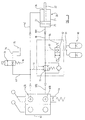
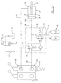
- a conventional accumulator means 30 made of, in the present example, steel and connected by a pipe 31 to a first control valve 32.
- a second control valve 33 is connected by a line 34 comprising flexible hoses and/or rigid pipes to an hydraulic reservoir or other low pressure area 35.
- Each control valve 32, 33 is an electrically operated solenoid valve and which is movable between a first or “at rest” position in which passage of fluid is prevented in one direction of the valve 32 and in both directions in the valve 33 and a second position in which passage of fluid is permitted. Both control valves 32, 33 are normally spring biased by a spring means 36 to the position in which flow of fluid is prevented as illustrated in Figure 2 and Figure 3.
- a line 38 comprising a rigid pipe 38 a and a flexible line 38 b , connects the first chamber 25 of the ram 20 to a first port 40 a of a selection valve 40 via a hose burst check valve 39.
- the first control valve 32 is connected by a line 37, comprising a rigid pipe, to the line 38 between ram chamber 25 and the hose burst check valve 39.
- the hose burst check valve 39 is a pilot valve that is normally maintained closed in the direction to prevent flow of fluid under pressure from the chamber 25 to the valve 40 but it may be opened by supply of pilot pressure on line 41, comprising a rigid pipe, from a line 42, comprising a rigid pipe 42 a and flexible hoses 42 b which extends between a second port 40 b of the selection valve 40 and the chamber 26 of the ram 20.
- the line 42 is connected by a line 43 to the second control valve 33.
- valves 32 and 33 In use, as best shown in Figure 2, during normal operation, when it is desired to lift the arm, fluid under pressure is fed from the first port 40 a of the selection valve 40 along the line 38 through the one-way check valve within the hose burst check valve 39. As boom suspension has not been selected there is no electrical supply to valves 32 and 33 and they remain in the normally closed position. As the telescopic boom 16 is raised, by the supply of fluid to the chamber 25, fluid under lower pressure is fed from the chamber 26 along line 42 into a port 40 b of the selection valve 40.
- the valve 33 of course, being, like the valve 32, maintained in the position shown in Figure 2 to prevent flow of fluid therethrough by virtue of no electrical supply being supplied to the solenoid thereof.
- valve 40 when it is desired to lower the loader arm assembly the valve 40 is actuated to feed fluid under pressure through port 40 b along line 42 into the chamber 26 and thus fluid under lower pressure is fed from chamber 25 along line 38 through hose burst check valve 39 which is maintained in an open position by virtue of supply of pilot pressure on line 41 which extends from line 42.
- valve 40 when it is desired to raise the loader arm assembly whilst the ride improvement means is engaged, the valve 40 is actuated to feed fluid from port 40 a under pressure along line 38 into the chamber 25 whilst fluid from the chamber 26 passes along the line 42 back to the valve 40. At the same time the suspension of the arm assembly is suspended by the accumulator 30 as described hereinbefore in connection with the Figure 4.
- valve 40 when it is desired to lower the boom whilst the ride improvement means is engaged, the actuation of the valve 40 to raise pressure at port 40 b , by virtue of switch 44, has the effect of collapsing the 7 electrical signal to valve 33 which becomes closed and so allows pressure to be raised in line 42 which feeds fluid under pressure to chamber 26, whilst fluid in chamber 25 is fed via line 38 through the hose burst check valve 39 to the port 40 a of the valve 40.
- the hose burst check valve 39 is maintained open by pilot pressure fluid on line 41 which extends from line 42.
- valves 32, 33 and check valve 39 are all disposed on the cylinder 21, if desired one or more of these components may be positioned as desired and made of material as desired where permitted by local regulations.
Landscapes
- Engineering & Computer Science (AREA)
- Structural Engineering (AREA)
- Civil Engineering (AREA)
- Transportation (AREA)
- Geology (AREA)
- Mining & Mineral Resources (AREA)
- General Engineering & Computer Science (AREA)
- Mechanical Engineering (AREA)
- Life Sciences & Earth Sciences (AREA)
- Chemical & Material Sciences (AREA)
- Combustion & Propulsion (AREA)
- Fluid-Pressure Circuits (AREA)
- Operation Control Of Excavators (AREA)
- Auxiliary Drives, Propulsion Controls, And Safety Devices (AREA)
- Lifting Devices For Agricultural Implements (AREA)
- Forklifts And Lifting Vehicles (AREA)
- Automatic Cycles, And Cycles In General (AREA)
- Organic Low-Molecular-Weight Compounds And Preparation Thereof (AREA)
- Excavating Of Shafts Or Tunnels (AREA)
- Vehicle Body Suspensions (AREA)
- Devices For Conveying Motion By Means Of Endless Flexible Members (AREA)
- Automobile Manufacture Line, Endless Track Vehicle, Trailer (AREA)
- Sheets, Magazines, And Separation Thereof (AREA)
Claims (6)
- Radlader mit einem hydraulischen System zum Bereitstellen eines Mittels zur Verbesserung des Fahrverhaltens, wobei das hydraulische System eine Ladeazmanordnung (16) umfaßt, die ein Arbeitsgerät (18) trägt und die mit einem Fahrgestell (10) des Laders verbunden ist, wobei die Ladearmanordnung (16) zwischen einer angehobenen und einer abgesenkten Position mit Hilfe einer hydraulischen Stempeleinrichtung (20) bewegbar ist, und wobei ein hydraulischer Speicher (30) mit der hydraulischen Stempeleinrichtung (20) verbunden ist, wobei die Ladearmanordnung (16) an oder benachbart zu dem hinteren Ende davon mit dem Fahrgestell (10) an oder benachbart zu dessen hinterem Ende verbunden ist, so daß sich die Ladearmanordnung (16) nach vorn erstreckt, so daß sich in einer abgesenkten Position der Ladearmanordnung (16) das Arbeitsgerät (18) vor dem Fahrgestell (10) befindet, wobei die erste Kammer (25) und die zweite Kammer (26) der hydraulischen Stempeleinrichtung (20) mit einer Umsteuenrentileinrichtung (40) verbunden sind, die dafür bestimmt ist, Fluid unter Druck an die erste Kammer (25) der Stempeleinrichtung (20) zuzuführen und Fluid unter einem niedrigeren Druck von der zweiten Kammer (26) der Stempeleiruichtung (20) aufzunehmen, um die Ladearmanordnung (16) anzuheben, oder um Fluid unter Druck an die zweite Kammer (26) der Stempeleinrichtung (20) zuzuführen und Fluid unter einem niedrigeren Druck von der ersten Kammer (25) der Stempeleinrichtung (20) aufzunehmen, um die Ladearmanordnung (16) abzusenken, wobei das hydraulische System weiterhin ein erstes und ein zweites Steuerventil (22, 23) umfaßt, dadurch gekennzeichnet, daß das erste Steuerventil (22) an eine Leitung (38) zwischen der ersten Kammer (25) und der Umsteuerventileinrichtung (40) sowie an den Speicher (30) angeschlossen ist, wobei das erste Steuerventil (32) zwischen einer ersten Position, in der ein Durchgang von hydraulischem Fluid durch dieses zu dem Speicher (30) verhindert ist, und einer zweiten Position, in der ein Durchgang von hydraulischem Fluid durch dieses hindurch möglich ist, bewegbar ist, und wobei das zweite Steuerventil (33) zwischen der zweiten Kammer (26) und einem Bereich mit niedrigem Druck (35) angeschlossen ist, wobei das zweite Steuerventil (33) zwischen einer ersten Position, in der ein Durchgang von hydraulischem Fluid durch dieses hindurch zu dem Bereich mit niedrigem Druck verhindert ist, und einer zweiten Position, in der ein Durchgang von hydraulischem Fluid durch dieses hindurch möglich ist, bewegbar ist, und wobei ein Rückschlagventil (39) in der Leitung (38) zwischen der ersten Kammer (25) und der Umsteuerventileinrichtung (40) angeordnet ist, zwischen der Umsteuerventileinrichtung (40) und dem Anschluß des ersten Steuerventils an die Leitung (38), so daß das Rückschlagventil (39) normalerweise geschlossen ist, um zu verhindern, daß Fluid unter Druck von der ersten Kammer (25) zu der Umsteuerventileinrichtung (40) gelangt, und wobei das Rückschlagventil (39) auf hydraulisches Fluid ansprechende Mittel aufweist, die auf einen hydraulischen Fluiddruck in der zweiten Kammer (26) ansprechen, um das Rückschlagventil (39) zu öffnen und wobei ein Mittel (41) vorhandes ist, um den hydraulischen Fluiddruck mit der zweiten Kammer (26) zu verbinden.
- Radlader nach Anspruch 1, dadurch gekennzeichnet, daß die Umsteuerventileinrichtung (40) von Hand betätigbar ist.
- Radlader nach Anspruch 1 oder 2, dadurch gekennzeichnet, daß die ersten und zweiten Rückschlagventile (32, 33) elektrisch betätigte Solenoidventile sind, an die ein Strom durch eine von Hand betätigbare Schalteinrichtung zugeführt wird, um die Steuerventile (32, 33) in ihre zweiten Positionen zu bewegen, um die Einrichtung zur Verbesserung des Fahrverhaltens bereitzustellen.
- Radlader nach Anspruch 2 oder 3, dadurch gekennzeichnet, daß die Umsteuerventileinrichtung (40) mit einer Schalteinrichtung (44) versehen ist, um die Position der Umsteuerventileinrichtung (40) zu erfassen, um das zweite Steuerventil (33) zu schließen, wenn die Ladearmanordnung (16) abgesenkt ist und wenn sich die Steuerventile (32, 33) in ihren zweiten Positionen befinden.
- Radlader nach einem der vorangehenden Ansprüche, dadurch gekennzeichnet, daß der Speicher (30) und die Steuerventile (32, 33) und das Rückschlagventil (39) unmittelbar auf der hydraulischen Stempeleinrichtung (20) angebracht sind.
- Radlader nach einem der vorangehenden Ansprüche, dadurch gekennzeichnet, daß zumindest eines der Elemente; Speicher (30), Steuerventile und Rückschlagventil (39) und Anschlußleitungen, aus Metall bestehen.
Priority Applications (4)
| Application Number | Priority Date | Filing Date | Title |
|---|---|---|---|
| EP04004513A EP1428789B1 (de) | 2000-05-25 | 2001-05-24 | Verfahren zum Betreiben eines hydraulischen Systems für einen Radlader |
| EP05000406A EP1522520B1 (de) | 2000-05-25 | 2001-05-24 | Verfahren zum Senken eines Laderauslegers |
| EP08158101A EP1961694B1 (de) | 2000-05-25 | 2001-05-24 | Radlader mit einer Laderarmanordnung. |
| DK01304608T DK1157963T3 (da) | 2000-05-25 | 2001-05-24 | Hydraulisk system til hjullæsser |
Applications Claiming Priority (2)
| Application Number | Priority Date | Filing Date | Title |
|---|---|---|---|
| GB0012602 | 2000-05-25 | ||
| GB0012602A GB2365407B (en) | 2000-05-25 | 2000-05-25 | Hydraulic system for wheeled loader |
Related Child Applications (1)
| Application Number | Title | Priority Date | Filing Date |
|---|---|---|---|
| EP04004513A Division EP1428789B1 (de) | 2000-05-25 | 2001-05-24 | Verfahren zum Betreiben eines hydraulischen Systems für einen Radlader |
Publications (3)
| Publication Number | Publication Date |
|---|---|
| EP1157963A2 EP1157963A2 (de) | 2001-11-28 |
| EP1157963A3 EP1157963A3 (de) | 2002-04-17 |
| EP1157963B1 true EP1157963B1 (de) | 2004-10-27 |
Family
ID=9892266
Family Applications (4)
| Application Number | Title | Priority Date | Filing Date |
|---|---|---|---|
| EP20010304608 Revoked EP1157963B1 (de) | 2000-05-25 | 2001-05-24 | Hydraulisches System für einen Radlader |
| EP04004513A Revoked EP1428789B1 (de) | 2000-05-25 | 2001-05-24 | Verfahren zum Betreiben eines hydraulischen Systems für einen Radlader |
| EP05000406A Revoked EP1522520B1 (de) | 2000-05-25 | 2001-05-24 | Verfahren zum Senken eines Laderauslegers |
| EP08158101A Revoked EP1961694B1 (de) | 2000-05-25 | 2001-05-24 | Radlader mit einer Laderarmanordnung. |
Family Applications After (3)
| Application Number | Title | Priority Date | Filing Date |
|---|---|---|---|
| EP04004513A Revoked EP1428789B1 (de) | 2000-05-25 | 2001-05-24 | Verfahren zum Betreiben eines hydraulischen Systems für einen Radlader |
| EP05000406A Revoked EP1522520B1 (de) | 2000-05-25 | 2001-05-24 | Verfahren zum Senken eines Laderauslegers |
| EP08158101A Revoked EP1961694B1 (de) | 2000-05-25 | 2001-05-24 | Radlader mit einer Laderarmanordnung. |
Country Status (8)
| Country | Link |
|---|---|
| US (1) | US7089734B2 (de) |
| EP (4) | EP1157963B1 (de) |
| AT (4) | ATE501974T1 (de) |
| DE (4) | DE60144256D1 (de) |
| DK (2) | DK1157963T3 (de) |
| ES (3) | ES2228758T3 (de) |
| GB (1) | GB2365407B (de) |
| PT (2) | PT1428789E (de) |
Cited By (2)
| Publication number | Priority date | Publication date | Assignee | Title |
|---|---|---|---|---|
| EP1764339A2 (de) | 2005-09-15 | 2007-03-21 | CNH Italia S.p.A. | Hydraulische Anordnung für einen an einem Fahrzeug schwenkbar gelagerten Auslegerarm |
| KR100953809B1 (ko) * | 2002-12-27 | 2010-04-21 | 두산인프라코어 주식회사 | 휠로더의 붐완충장치 |
Families Citing this family (29)
| Publication number | Priority date | Publication date | Assignee | Title |
|---|---|---|---|---|
| US7204086B2 (en) * | 2000-05-25 | 2007-04-17 | J.C Bamford Excavators Limited | Method of operating a hydraulic system for a loader machine |
| DE10227966A1 (de) | 2002-06-22 | 2004-01-08 | Deere & Company, Moline | Hydraulische Steueranordnung für eine mobile Arbeitsmaschine |
| US7383906B2 (en) | 2002-08-29 | 2008-06-10 | Jlg Industries, Inc. | Rotatable and telescopic work machine |
| DE10305790A1 (de) * | 2003-02-07 | 2004-08-26 | Hydac System Gmbh | Federungsvorrichtung |
| DE10336684A1 (de) * | 2003-08-09 | 2005-03-03 | Deere & Company, Moline | Hydraulische Steueranordnung für eine mobile Arbeitsmaschine |
| DE102004010053A1 (de) * | 2004-03-02 | 2005-09-29 | Hydac System Gmbh | Federungsvorrichtung |
| DE102004012362A1 (de) * | 2004-03-13 | 2005-09-22 | Deere & Company, Moline | Hydraulische Anordnung |
| US7377523B2 (en) * | 2004-05-17 | 2008-05-27 | Husco International, Inc. | Hydraulic suspension with a lock-out mechanism for an off-highway vehicle |
| DE102004032868A1 (de) * | 2004-07-07 | 2006-02-09 | Liebherr-Hydraulikbagger Gmbh | Bagger und Maschine zum Materialumschlag |
| GB2418903B (en) * | 2004-10-08 | 2008-06-25 | Caterpillar Inc | Ride control circuit for a work machine |
| DE602004011077T2 (de) * | 2004-11-12 | 2009-01-02 | Parker Hannifin Ab | Niveauregulierung |
| DE102004056418B4 (de) * | 2004-11-23 | 2013-02-28 | Deere & Company | Hydraulische Anordnung |
| FR2881126B1 (fr) * | 2005-01-21 | 2007-03-30 | Hydrokit Soc Par Actions Simpl | Engin roulant du type muni d'un bras, comportant un dispositif d'amortissement du bras. |
| ATE425118T1 (de) * | 2005-06-15 | 2009-03-15 | Bosch Rexroth Oil Control S P | Hydraulische vorrichtung zum heben und senken eines an einer arbeitsmaschine schwenkbaren arms |
| DE102005033154A1 (de) | 2005-07-13 | 2007-01-18 | Deere & Company, Moline | Hydraulische Anordnung |
| DE102005038333A1 (de) | 2005-08-11 | 2007-02-15 | Deere & Company, Moline | Hydraulische Anordnung |
| US20080093093A1 (en) * | 2006-10-24 | 2008-04-24 | Morris Industries Ltd | Combination Hydraulic Hold-Down and Lift System for an Agricultural Implement |
| ATE430085T1 (de) * | 2007-01-24 | 2009-05-15 | Klemm Bohrtechnik Gmbh | Pendelfahrwerk, insbesondere für ein bohrgerät |
| GB2451244B (en) * | 2007-07-21 | 2011-09-28 | Bamford Excavators Ltd | Working machine |
| FR2923352B1 (fr) * | 2007-11-12 | 2010-01-15 | Signalisation Moderne Autoroutiere Sma | Machine de fauchage/debroussaillage/elagage munie d'un moyen d'amortissement de chocs |
| US7827787B2 (en) | 2007-12-27 | 2010-11-09 | Deere & Company | Hydraulic system |
| US9055719B2 (en) * | 2012-12-06 | 2015-06-16 | Deere & Company | Method and apparatus for ride control activation |
| US10030676B2 (en) * | 2014-04-23 | 2018-07-24 | Hyster—Yale Group, Inc. | Hydraulic fluid supply apparatus and methods |
| AR101237A1 (es) * | 2014-05-14 | 2016-12-07 | Castro Salinas Moisés | Válvula de seguridad para sistema hidráulico de elevación de tolva de camiones compactadores |
| JP6532427B2 (ja) * | 2016-04-26 | 2019-06-19 | 株式会社クボタ | 作業車 |
| CN109573895A (zh) * | 2018-12-29 | 2019-04-05 | 航天重型工程装备有限公司 | 一种蓄电池铲运装置 |
| GB2623565B8 (en) * | 2022-10-20 | 2025-07-23 | Bamford Excavators Ltd | A material handling machine |
| GB2632718A (en) * | 2023-08-18 | 2025-02-19 | Bamford Excavators Ltd | Controlled actuation in a working machine |
| US12419204B1 (en) * | 2024-05-24 | 2025-09-23 | Cnh Industrial America Llc | System and method for controlling the operation of an agricultural implement |
Family Cites Families (32)
| Publication number | Priority date | Publication date | Assignee | Title |
|---|---|---|---|---|
| US3866700A (en) * | 1969-02-20 | 1975-02-18 | Clark Equipment Co | Tractor vehicle with hydrostatic drive means |
| US4367673A (en) * | 1981-01-09 | 1983-01-11 | Dresser Industries, Inc. | System and method for controlling the elevation of a boom hoist device |
| JPS58121305A (ja) * | 1982-01-11 | 1983-07-19 | Kobe Steel Ltd | 油圧シリンダの伸縮保持用油圧回路 |
| JPS5973602A (ja) | 1982-10-20 | 1984-04-25 | Tadano Tekkosho:Kk | 負荷を担持する油圧シリンダの負荷担持側油室の圧力補償装置 |
| US4522109A (en) * | 1983-11-21 | 1985-06-11 | J. I. Case Company | Leak-detecting hydraulic system |
| US4658970A (en) * | 1985-11-15 | 1987-04-21 | Kobe Steel Ltd. | Deflection reduction module for boom hoist cylinder of mobile crane |
| JPS63265023A (ja) * | 1987-04-20 | 1988-11-01 | Kobe Steel Ltd | 車両系建設機械の振動抑制装置 |
| JPS6466324A (en) | 1987-09-08 | 1989-03-13 | Kobe Steel Ltd | Vibration suppressor for vehicular construction machine |
| JPS6466321A (en) | 1987-09-08 | 1989-03-13 | Kobe Steel Ltd | Vibration insulator for vehicular construction machine |
| JPH01256494A (ja) | 1988-04-01 | 1989-10-12 | Kobe Steel Ltd | 移動式クレーンの変位抑制装置 |
| WO1990005814A1 (en) * | 1988-11-23 | 1990-05-31 | A & T Hansson Konsult Ab | Shock absorbing device for a mobile machine |
| DE3909205C1 (de) | 1989-03-21 | 1990-05-23 | Hanomag Ag, 3000 Hannover, De | |
| JPH0662268B2 (ja) | 1989-04-21 | 1994-08-17 | 株式会社神戸製鋼所 | 移動式クレーンの変位抑制装置 |
| JPH0662269B2 (ja) * | 1989-04-21 | 1994-08-17 | 株式会社神戸製鋼所 | 移動式クレーンの変位抑制装置 |
| JPH0662270B2 (ja) | 1989-05-10 | 1994-08-17 | 株式会社神戸製鋼所 | 移動式クレーンの変位抑制装置 |
| JPH0336194A (ja) | 1989-07-03 | 1991-02-15 | Kobe Steel Ltd | 移動式クレーンの変位抑制機構 |
| JPH0639315B2 (ja) | 1989-07-03 | 1994-05-25 | 株式会社神戸製鋼所 | 移動式クレーンの変位抑制機構 |
| JPH0639317B2 (ja) | 1989-09-09 | 1994-05-25 | 株式会社神戸製鋼所 | 移動式クレーンの変位抑制機構 |
| JPH0815998B2 (ja) | 1989-10-14 | 1996-02-21 | 株式会社神戸製鋼所 | ホイール式クレーンの振動抑制装置 |
| US5195864A (en) * | 1991-08-28 | 1993-03-23 | Case Corporation | Hydraulic system for a wheel loader |
| DE4221943C2 (de) | 1991-09-04 | 1996-01-25 | Orenstein & Koppel Ag | Hydraulikanlage für mit Arbeitsgeräten versehene fahrbare Arbeitsmaschinen |
| ATE150508T1 (de) * | 1991-09-04 | 1997-04-15 | Orenstein & Koppel Ag | Hydraulisches schwingungsdämpfungssystem für mit arbeitsgeräten versehene arbeitsmaschinen |
| JP3129495B2 (ja) * | 1991-12-13 | 2001-01-29 | 株式会社小松製作所 | 昇降作業機の位置エネルギ回収装置 |
| FR2710372B1 (fr) | 1993-09-22 | 1995-11-17 | Alain Bourgeois | Dispositif de commande hydraulique d'un vérin à double effet. |
| JPH0978633A (ja) * | 1995-09-13 | 1997-03-25 | Komatsu Ltd | 車輪式建設機械の走行振動抑制油圧回路 |
| US5706657A (en) | 1996-04-12 | 1998-01-13 | Caterpillar Inc. | Ride control system with an auxiliary power source |
| GB2327076A (en) | 1997-07-08 | 1999-01-13 | Bamford Excavators Ltd | Hydraulic crowd mechanisms |
| DE19734658A1 (de) | 1997-08-11 | 1999-02-18 | Mannesmann Rexroth Ag | Hydraulische Steueranordnung für eine mobile Arbeitsmaschine, insbesondere für einen Radlader |
| US6167701B1 (en) | 1998-07-06 | 2001-01-02 | Caterpillar Inc. | Variable rate ride control |
| DE19913784A1 (de) * | 1999-03-26 | 2000-09-28 | Mannesmann Rexroth Ag | Lastfühlende hydraulische Steueranordnung für eine mobile Arbeitsmaschine |
| US6407562B1 (en) * | 1999-07-29 | 2002-06-18 | Agilent Technologies, Inc. | Probe tip terminating device providing an easily changeable feed-through termination |
| US6357230B1 (en) * | 1999-12-16 | 2002-03-19 | Caterpillar Inc. | Hydraulic ride control system |
-
2000
- 2000-05-25 GB GB0012602A patent/GB2365407B/en not_active Expired - Lifetime
-
2001
- 2001-05-24 DE DE60144256T patent/DE60144256D1/de not_active Expired - Lifetime
- 2001-05-24 DK DK01304608T patent/DK1157963T3/da active
- 2001-05-24 DE DE60106671T patent/DE60106671T9/de not_active Revoked
- 2001-05-24 DK DK04004513T patent/DK1428789T3/da active
- 2001-05-24 AT AT08158101T patent/ATE501974T1/de active
- 2001-05-24 EP EP20010304608 patent/EP1157963B1/de not_active Revoked
- 2001-05-24 ES ES01304608T patent/ES2228758T3/es not_active Expired - Lifetime
- 2001-05-24 AT AT01304608T patent/ATE280733T1/de active
- 2001-05-24 EP EP04004513A patent/EP1428789B1/de not_active Revoked
- 2001-05-24 ES ES08158101T patent/ES2362809T3/es not_active Expired - Lifetime
- 2001-05-24 PT PT04004513T patent/PT1428789E/pt unknown
- 2001-05-24 ES ES04004513T patent/ES2240952T3/es not_active Expired - Lifetime
- 2001-05-24 EP EP05000406A patent/EP1522520B1/de not_active Revoked
- 2001-05-24 PT PT01304608T patent/PT1157963E/pt unknown
- 2001-05-24 EP EP08158101A patent/EP1961694B1/de not_active Revoked
- 2001-05-24 AT AT04004513T patent/ATE294133T1/de not_active IP Right Cessation
- 2001-05-24 DE DE60110472T patent/DE60110472T2/de not_active Revoked
- 2001-05-24 DE DE60134583T patent/DE60134583D1/de not_active Expired - Fee Related
- 2001-05-24 AT AT05000406T patent/ATE399142T1/de not_active IP Right Cessation
- 2001-05-25 US US09/866,311 patent/US7089734B2/en not_active Expired - Lifetime
Cited By (2)
| Publication number | Priority date | Publication date | Assignee | Title |
|---|---|---|---|---|
| KR100953809B1 (ko) * | 2002-12-27 | 2010-04-21 | 두산인프라코어 주식회사 | 휠로더의 붐완충장치 |
| EP1764339A2 (de) | 2005-09-15 | 2007-03-21 | CNH Italia S.p.A. | Hydraulische Anordnung für einen an einem Fahrzeug schwenkbar gelagerten Auslegerarm |
Also Published As
| Publication number | Publication date |
|---|---|
| DE60144256D1 (de) | 2011-04-28 |
| EP1961694A1 (de) | 2008-08-27 |
| DE60134583D1 (de) | 2008-08-07 |
| GB2365407B (en) | 2003-10-08 |
| EP1157963A2 (de) | 2001-11-28 |
| PT1428789E (pt) | 2005-06-30 |
| ES2362809T3 (es) | 2011-07-13 |
| EP1522520A2 (de) | 2005-04-13 |
| ES2240952T3 (es) | 2005-10-16 |
| EP1961694B1 (de) | 2011-03-16 |
| ES2228758T3 (es) | 2005-04-16 |
| DE60110472T2 (de) | 2005-09-29 |
| EP1522520A3 (de) | 2005-04-20 |
| DE60106671D1 (de) | 2004-12-02 |
| US20020001516A1 (en) | 2002-01-03 |
| ATE280733T1 (de) | 2004-11-15 |
| DK1428789T3 (da) | 2005-09-19 |
| EP1428789A3 (de) | 2004-06-30 |
| DK1157963T3 (da) | 2005-02-14 |
| ATE399142T1 (de) | 2008-07-15 |
| ATE294133T1 (de) | 2005-05-15 |
| EP1428789B1 (de) | 2005-04-27 |
| EP1428789A2 (de) | 2004-06-16 |
| ATE501974T1 (de) | 2011-04-15 |
| DE60110472D1 (de) | 2005-06-02 |
| EP1522520B1 (de) | 2008-06-25 |
| DE60106671T2 (de) | 2005-04-07 |
| US7089734B2 (en) | 2006-08-15 |
| DE60106671T9 (de) | 2005-09-15 |
| PT1157963E (pt) | 2005-03-31 |
| GB0012602D0 (en) | 2000-07-12 |
| EP1157963A3 (de) | 2002-04-17 |
| GB2365407A (en) | 2002-02-20 |
Similar Documents
| Publication | Publication Date | Title |
|---|---|---|
| EP1522520B1 (de) | Verfahren zum Senken eines Laderauslegers | |
| US4359931A (en) | Regenerative and anticavitation hydraulic system for an excavator | |
| CA2629021C (en) | Dozer blade pitch control system | |
| JP3723594B2 (ja) | スキッド・ステア・ローダのリフトアームの制御装置 | |
| JPH02282192A (ja) | 移動式クレーンの変位抑制装置 | |
| AU2008203225B2 (en) | Working machine | |
| US6196586B1 (en) | System for frame leveling and stabilizing a forklift | |
| EP3507422B1 (de) | Hubwerk | |
| US20070251129A1 (en) | Method of operating a hydraulic system for a loader machine | |
| EP1764339B1 (de) | Hydraulische Anordnung für einen an einem Fahrzeug schwenkbar gelagerten Auslegerarm | |
| EP1657213B1 (de) | Niveauregulierung | |
| US20090057045A1 (en) | Hydraulic system to deter lift arm chatter | |
| EP1502894B1 (de) | Lasthandhabungsgerät | |
| US4018350A (en) | Hydraulic cyliner systems with safeguarded float action | |
| GB2055977A (en) | Hydraulic control systems | |
| JPS6330546B2 (de) | ||
| JPS649483B2 (de) | ||
| JPS5940564Y2 (ja) | 農用フロントロ−ダ | |
| JPH05195561A (ja) | 建設機械の油圧緩衝制御装置 | |
| JPH01309859A (ja) | 特殊車両におけるアウトリガの伸長防止装置 | |
| JPH1181390A (ja) | 作業機の油圧回路 | |
| WO2007022546A1 (en) | Control systems for earth working equipment | |
| JPH0643058U (ja) | 土工車両の非常時ブーム下降装置 |
Legal Events
| Date | Code | Title | Description |
|---|---|---|---|
| PUAI | Public reference made under article 153(3) epc to a published international application that has entered the european phase |
Free format text: ORIGINAL CODE: 0009012 |
|
| AK | Designated contracting states |
Kind code of ref document: A2 Designated state(s): AT BE CH CY DE DK ES FI FR GB GR IE IT LI LU MC NL PT SE TR |
|
| AX | Request for extension of the european patent |
Free format text: AL;LT;LV;MK;RO;SI |
|
| PUAL | Search report despatched |
Free format text: ORIGINAL CODE: 0009013 |
|
| AK | Designated contracting states |
Kind code of ref document: A3 Designated state(s): AT BE CH CY DE DK ES FI FR GB GR IE IT LI LU MC NL PT SE TR |
|
| AX | Request for extension of the european patent |
Free format text: AL;LT;LV;MK;RO;SI |
|
| 17P | Request for examination filed |
Effective date: 20020919 |
|
| AKX | Designation fees paid |
Free format text: AT BE CH CY DE DK ES FI FR GB GR IE IT LI LU MC NL PT SE TR |
|
| 17Q | First examination report despatched |
Effective date: 20031121 |
|
| GRAP | Despatch of communication of intention to grant a patent |
Free format text: ORIGINAL CODE: EPIDOSNIGR1 |
|
| GRAS | Grant fee paid |
Free format text: ORIGINAL CODE: EPIDOSNIGR3 |
|
| GRAA | (expected) grant |
Free format text: ORIGINAL CODE: 0009210 |
|
| AK | Designated contracting states |
Kind code of ref document: B1 Designated state(s): AT BE CH CY DE DK ES FI FR GB GR IE IT LI LU MC NL PT SE TR |
|
| REG | Reference to a national code |
Ref country code: GB Ref legal event code: FG4D |
|
| REG | Reference to a national code |
Ref country code: CH Ref legal event code: EP |
|
| REG | Reference to a national code |
Ref country code: CH Ref legal event code: NV Representative=s name: ISLER & PEDRAZZINI AG |
|
| REG | Reference to a national code |
Ref country code: IE Ref legal event code: FG4D |
|
| REF | Corresponds to: |
Ref document number: 60106671 Country of ref document: DE Date of ref document: 20041202 Kind code of ref document: P |
|
| ET | Fr: translation filed | ||
| REG | Reference to a national code |
Ref country code: DK Ref legal event code: T3 |
|
| REG | Reference to a national code |
Ref country code: GR Ref legal event code: EP Ref document number: 20050400162 Country of ref document: GR |
|
| REG | Reference to a national code |
Ref country code: SE Ref legal event code: TRGR |
|
| REG | Reference to a national code |
Ref country code: PT Ref legal event code: SC4A Free format text: AVAILABILITY OF NATIONAL TRANSLATION Effective date: 20050114 |
|
| REG | Reference to a national code |
Ref country code: ES Ref legal event code: FG2A Ref document number: 2228758 Country of ref document: ES Kind code of ref document: T3 |
|
| REG | Reference to a national code |
Ref country code: FR Ref legal event code: CL |
|
| PG25 | Lapsed in a contracting state [announced via postgrant information from national office to epo] |
Ref country code: MC Free format text: LAPSE BECAUSE OF NON-PAYMENT OF DUE FEES Effective date: 20050531 |
|
| PLAQ | Examination of admissibility of opposition: information related to despatch of communication + time limit deleted |
Free format text: ORIGINAL CODE: EPIDOSDOPE2 |
|
| PLBI | Opposition filed |
Free format text: ORIGINAL CODE: 0009260 |
|
| PLBQ | Unpublished change to opponent data |
Free format text: ORIGINAL CODE: EPIDOS OPPO |
|
| PLAQ | Examination of admissibility of opposition: information related to despatch of communication + time limit deleted |
Free format text: ORIGINAL CODE: EPIDOSDOPE2 |
|
| PLAR | Examination of admissibility of opposition: information related to receipt of reply deleted |
Free format text: ORIGINAL CODE: EPIDOSDOPE4 |
|
| PLBQ | Unpublished change to opponent data |
Free format text: ORIGINAL CODE: EPIDOS OPPO |
|
| PLAB | Opposition data, opponent's data or that of the opponent's representative modified |
Free format text: ORIGINAL CODE: 0009299OPPO |
|
| 26 | Opposition filed |
Opponent name: CNH BELGIUM N.V. Effective date: 20050524 |
|
| PLBI | Opposition filed |
Free format text: ORIGINAL CODE: 0009260 |
|
| PLBI | Opposition filed |
Free format text: ORIGINAL CODE: 0009260 |
|
| PLBI | Opposition filed |
Free format text: ORIGINAL CODE: 0009260 |
|
| R26 | Opposition filed (corrected) |
Opponent name: CNH BELGIUM N.V. Effective date: 20050524 |
|
| PLAX | Notice of opposition and request to file observation + time limit sent |
Free format text: ORIGINAL CODE: EPIDOSNOBS2 |
|
| NLR1 | Nl: opposition has been filed with the epo |
Opponent name: CNH BELGIUM N.V. |
|
| 26 | Opposition filed |
Opponent name: MANITOU BF Effective date: 20050714 Opponent name: CNH BELGIUM N.V. Effective date: 20050524 |
|
| 26 | Opposition filed |
Opponent name: CNH BELGIUM N.V. Effective date: 20050524 Opponent name: MANITOU BF Effective date: 20050714 Opponent name: DEERE & COMPANY Effective date: 20050726 |
|
| 26 | Opposition filed |
Opponent name: CNH BELGIUM N.V. Effective date: 20050524 Opponent name: DEERE & COMPANY Effective date: 20050726 Opponent name: MANITOU BF Effective date: 20050714 Opponent name: CATERPILLAR (U.K.) LIMITED Effective date: 20050727 |
|
| NLR1 | Nl: opposition has been filed with the epo |
Opponent name: CNH BELGIUM N.V. |
|
| NLR1 | Nl: opposition has been filed with the epo |
Opponent name: CNH BELGIUM N.V. Opponent name: DEERE & COMPANY Opponent name: MANITOU BF |
|
| NLR1 | Nl: opposition has been filed with the epo |
Opponent name: CNH BELGIUM N.V. Opponent name: CATERPILLAR (U.K.) LIMITED Opponent name: DEERE & COMPANY Opponent name: MANITOU BF |
|
| PLBB | Reply of patent proprietor to notice(s) of opposition received |
Free format text: ORIGINAL CODE: EPIDOSNOBS3 |
|
| REG | Reference to a national code |
Ref country code: CH Ref legal event code: PCAR Free format text: ISLER & PEDRAZZINI AG;POSTFACH 1772;8027 ZUERICH (CH) |
|
| APBP | Date of receipt of notice of appeal recorded |
Free format text: ORIGINAL CODE: EPIDOSNNOA2O |
|
| APAH | Appeal reference modified |
Free format text: ORIGINAL CODE: EPIDOSCREFNO |
|
| APBM | Appeal reference recorded |
Free format text: ORIGINAL CODE: EPIDOSNREFNO |
|
| APBP | Date of receipt of notice of appeal recorded |
Free format text: ORIGINAL CODE: EPIDOSNNOA2O |
|
| APBP | Date of receipt of notice of appeal recorded |
Free format text: ORIGINAL CODE: EPIDOSNNOA2O |
|
| APBP | Date of receipt of notice of appeal recorded |
Free format text: ORIGINAL CODE: EPIDOSNNOA2O |
|
| APBQ | Date of receipt of statement of grounds of appeal recorded |
Free format text: ORIGINAL CODE: EPIDOSNNOA3O |
|
| APBQ | Date of receipt of statement of grounds of appeal recorded |
Free format text: ORIGINAL CODE: EPIDOSNNOA3O |
|
| APBQ | Date of receipt of statement of grounds of appeal recorded |
Free format text: ORIGINAL CODE: EPIDOSNNOA3O |
|
| APBQ | Date of receipt of statement of grounds of appeal recorded |
Free format text: ORIGINAL CODE: EPIDOSNNOA3O |
|
| PLAB | Opposition data, opponent's data or that of the opponent's representative modified |
Free format text: ORIGINAL CODE: 0009299OPPO |
|
| PGFP | Annual fee paid to national office [announced via postgrant information from national office to epo] |
Ref country code: PT Payment date: 20100510 Year of fee payment: 10 Ref country code: LU Payment date: 20100518 Year of fee payment: 10 Ref country code: FR Payment date: 20100525 Year of fee payment: 10 Ref country code: IE Payment date: 20100514 Year of fee payment: 10 Ref country code: ES Payment date: 20100611 Year of fee payment: 10 Ref country code: FI Payment date: 20100512 Year of fee payment: 10 Ref country code: DK Payment date: 20100512 Year of fee payment: 10 |
|
| PGFP | Annual fee paid to national office [announced via postgrant information from national office to epo] |
Ref country code: DE Payment date: 20100519 Year of fee payment: 10 Ref country code: AT Payment date: 20100512 Year of fee payment: 10 |
|
| APBU | Appeal procedure closed |
Free format text: ORIGINAL CODE: EPIDOSNNOA9O |
|
| PGFP | Annual fee paid to national office [announced via postgrant information from national office to epo] |
Ref country code: BE Payment date: 20100518 Year of fee payment: 10 Ref country code: CH Payment date: 20100514 Year of fee payment: 10 |
|
| RDAF | Communication despatched that patent is revoked |
Free format text: ORIGINAL CODE: EPIDOSNREV1 |
|
| RDAG | Patent revoked |
Free format text: ORIGINAL CODE: 0009271 |
|
| STAA | Information on the status of an ep patent application or granted ep patent |
Free format text: STATUS: PATENT REVOKED |
|
| PGFP | Annual fee paid to national office [announced via postgrant information from national office to epo] |
Ref country code: GB Payment date: 20100519 Year of fee payment: 10 Ref country code: SE Payment date: 20100510 Year of fee payment: 10 |
|
| REG | Reference to a national code |
Ref country code: CH Ref legal event code: PL |
|
| 27W | Patent revoked |
Effective date: 20101007 |
|
| GBPR | Gb: patent revoked under art. 102 of the ep convention designating the uk as contracting state |
Effective date: 20101007 |
|
| REG | Reference to a national code |
Ref country code: PT Ref legal event code: MP4A Effective date: 20101215 |
|
| PGFP | Annual fee paid to national office [announced via postgrant information from national office to epo] |
Ref country code: GR Payment date: 20100429 Year of fee payment: 10 |
|
| REG | Reference to a national code |
Ref country code: SE Ref legal event code: ECNC |
|
| PG25 | Lapsed in a contracting state [announced via postgrant information from national office to epo] |
Ref country code: LI Free format text: LAPSE BECAUSE OF THE APPLICANT RENOUNCES Effective date: 20041027 Ref country code: CH Free format text: LAPSE BECAUSE OF THE APPLICANT RENOUNCES Effective date: 20041027 |
|
| PGFP | Annual fee paid to national office [announced via postgrant information from national office to epo] |
Ref country code: TR Payment date: 20110429 Year of fee payment: 11 |
|
| PGFP | Annual fee paid to national office [announced via postgrant information from national office to epo] |
Ref country code: NL Payment date: 20110526 Year of fee payment: 11 |
|
| PGFP | Annual fee paid to national office [announced via postgrant information from national office to epo] |
Ref country code: IT Payment date: 20110520 Year of fee payment: 11 |
|
| PGFP | Annual fee paid to national office [announced via postgrant information from national office to epo] |
Ref country code: CY Payment date: 20110509 Year of fee payment: 11 |
|
| REG | Reference to a national code |
Ref country code: DE Ref legal event code: R119 Ref document number: 60106671 Country of ref document: DE Effective date: 20121201 |