EP1160137A2 - Module de coussin gonflable avec générateur de gaz servant de masse d'atténuation de vibrations - Google Patents
Module de coussin gonflable avec générateur de gaz servant de masse d'atténuation de vibrations Download PDFInfo
- Publication number
- EP1160137A2 EP1160137A2 EP00124957A EP00124957A EP1160137A2 EP 1160137 A2 EP1160137 A2 EP 1160137A2 EP 00124957 A EP00124957 A EP 00124957A EP 00124957 A EP00124957 A EP 00124957A EP 1160137 A2 EP1160137 A2 EP 1160137A2
- Authority
- EP
- European Patent Office
- Prior art keywords
- airbag module
- module according
- sealing lip
- airbag
- gas generator
- Prior art date
- Legal status (The legal status is an assumption and is not a legal conclusion. Google has not performed a legal analysis and makes no representation as to the accuracy of the status listed.)
- Withdrawn
Links
- 238000013016 damping Methods 0.000 title abstract description 3
- 238000007789 sealing Methods 0.000 claims description 40
- 239000013013 elastic material Substances 0.000 claims description 5
- 238000004073 vulcanization Methods 0.000 claims description 3
- 239000007789 gas Substances 0.000 description 45
- 230000006378 damage Effects 0.000 description 3
- 239000000463 material Substances 0.000 description 2
- 125000006850 spacer group Chemical group 0.000 description 2
- 239000006096 absorbing agent Substances 0.000 description 1
- 230000001133 acceleration Effects 0.000 description 1
- 230000009286 beneficial effect Effects 0.000 description 1
- 238000010276 construction Methods 0.000 description 1
- 238000004880 explosion Methods 0.000 description 1
- 230000003993 interaction Effects 0.000 description 1
- 238000004519 manufacturing process Methods 0.000 description 1
- 238000000034 method Methods 0.000 description 1
- 230000010355 oscillation Effects 0.000 description 1
- 230000001960 triggered effect Effects 0.000 description 1
- 239000004636 vulcanized rubber Substances 0.000 description 1
Images


Classifications
-
- B—PERFORMING OPERATIONS; TRANSPORTING
- B60—VEHICLES IN GENERAL
- B60R—VEHICLES, VEHICLE FITTINGS, OR VEHICLE PARTS, NOT OTHERWISE PROVIDED FOR
- B60R21/00—Arrangements or fittings on vehicles for protecting or preventing injuries to occupants or pedestrians in case of accidents or other traffic risks
- B60R21/02—Occupant safety arrangements or fittings, e.g. crash pads
- B60R21/16—Inflatable occupant restraints or confinements designed to inflate upon impact or impending impact, e.g. air bags
- B60R21/20—Arrangements for storing inflatable members in their non-use or deflated condition; Arrangement or mounting of air bag modules or components
- B60R21/203—Arrangements for storing inflatable members in their non-use or deflated condition; Arrangement or mounting of air bag modules or components in steering wheels or steering columns
- B60R21/2035—Arrangements for storing inflatable members in their non-use or deflated condition; Arrangement or mounting of air bag modules or components in steering wheels or steering columns using modules containing inflator, bag and cover attachable to the steering wheel as a complete sub-unit
- B60R21/2037—Arrangements for storing inflatable members in their non-use or deflated condition; Arrangement or mounting of air bag modules or components in steering wheels or steering columns using modules containing inflator, bag and cover attachable to the steering wheel as a complete sub-unit the module or a major component thereof being yieldably mounted, e.g. for actuating the horn switch or for protecting the driver in a non-deployment situation
Definitions
- the invention relates to an airbag module for a motor vehicle steering wheel with a Airbag housing and one radially movable to the airbag housing connected, the function of a vibration damper mass accepting gas generator.
- the invention has for its object a constructive training for to find the airbag module in which the disadvantages mentioned avoided become.
- the gas generator of the airbag module should be as Serve vibration damper mass, but be suspended so that its Damage excluded. They are also said to be bothersome Noises can be avoided. After all, the connection should be simple and be easy to manufacture.
- the solution to the problem is an airbag module at the beginning mentioned genus according to the invention achieved in that the Gas generator via a provided with at least three rubber bars, as Washer formed adapter plate connected to the airbag housing is.
- the gas generator used has a rotating one Fastening flange with which it is connected gas-tight to the adapter plate is. This can be done for example by a screw connection.
- the gas-tight connection is therefore necessary so that the The airbag does not release gases that arise in unintended directions can escape.
- the mounting flange and the adapter plate can be formed as an integral part.
- the rubber bars are attached to the adapter plate in a stand-like manner. At her protruding ends they are provided with fastening tabs over which they can be connected to the airbag housing.
- the attachment of the Rubber webs with the adapter plate and the fastening tabs are through Vulcanization reached. A positive connection is also possible, for example by tying it in.
- a circumferential axially protruding, made of elastic material Sealing lip arranged on the airbag housing attached ring wall together in such a way that between the Sealing lip and the ring wall is a distance that the Gas generator gives sufficient freedom of swing, but one pressure created by the gas explosion is covered by the sealing lip is closed so that the annular space between the sealing lip and the annular wall and no gases can escape to the outside.
- the annular gap between the sealing lip and the associated ring wall of the Airbag housing is dimensioned so that the sealing lip in Interaction with the ring wall also as a stopper for the Vibration path of the gas generator is used.
- the ring wall can be a separate part attached to the airbag housing his. It is beneficial if the outer edge of the sealing lip becomes one elastic pointed edge is formed, with which it directly on the ring wall is present. Such a pointed edge hinders the swinging movement of the Gas generator in no way, but forms in the case of one Generator trigger a tight seal for the gases.
- the sealing lip is vulcanized onto the adapter plate.
- the vulcanizing process for the rubber ridges and the sealing lip is all in one Work performed.
- sealing lip is also possible.
- the sealing lip As An attachment of the sealing lip on the ring wall of the Airbag housing proven.
- the sealing lip then consists of one elastic material manufactured circumferential radial sealing lip that at least partially covers the adapter plate in the radial direction. At When the gas generator is triggered, the sealing lip turns on in the axial direction pressed the adapter plate and thus prevents gases from accidentally can exit outside.
- the sealing lip is with a small axial distance attached to the adapter plate, so that with the normally occurring Vibrations of the gas generator no contact between the sealing lip and the adapter plate is given.
- the sealing lip is attached preferably at the lower edge of the ring wall of the airbag housing.
- Airbag housing protrudes and is covered by a diffuser.
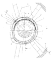
- FIG. 1 the arrangement and attachment of the Gas generator 1 shown in the airbag module 2.
- the airbag module 2 is in known manner essentially from the airbag housing 3, the Gas generator 1, the gas bag and the airbag housing 3 final cover.
- the airbag housing 3 is more suitable on the indicated steering wheel 4 Way attached.
- the gas generator 1 serves as a vibration damper mass. For this purpose, it is resilient with the airbag housing 3 via four rubber webs 5 connected.
- On the left side of FIG. 1 is the housing base 6 and Diffuser visible.
- the diffuser consists of the struts 7, which are star-shaped a center ring 8 go out.
- the gas generator is located below the struts 7 1, which is inserted into the housing base 6.
- the mounting flange 9 On the right side of Fig. 1, the gas generator 1 is visible, the circumferential mounting flange 9 has.
- the mounting flange 9 is with provided four tabs 10 projecting outwards. Over into the tabs 10 insertable screw connections 11 is the connection to the Adapter plate 12 made.
- the adapter plate 12 has the shape of a Washer and is gas-tight with the mounting flange 9 of the Gas generator 1 connected.
- the adapter plate 12 is with the tab 14 provided to which the rubber webs 5, seen on the Fig. down pointing, are appropriate. At the downward facing ends of the Rubber webs 5 connect fastening tabs 15, via which the Gas generator 1 is ultimately connected to the airbag housing 3.
- the Rubber webs 5 are in turn through with the tabs 14 and the tabs 15 Vulcanization connected.
- On the adapter plate 12 On the adapter plate 12 is the axially upwards protruding sealing lip 20 attached.
- FIG. 2 shows a longitudinal section on one side along the line A-A of FIG. 1.
- the gas generator 1 inserted in the housing base 6 has the rotating one Flange 9, which rests gas-tight on the adapter plate 12.
- On the after the outer edge 21 of the adapter plate 12 is the sealing lip 20 appropriate.
- the housing base 6 is with a ring pointing downwards 22 equipped. Ring 22 and sealing lip 20 have approximately the same height.
- An annular gap 23 is present between the ring 22 and the sealing lip 20, which allows sufficient oscillation of the gas generator 1.
- the Annular gap 23 is dimensioned such that if the deflections are too large Gas generator 1, the sealing lip 20 comes to rest on the ring wall 22 and thereby limits the vibration path of the gas generator 1.
- FIG. 3 shows a longitudinal section through the airbag module along the line B-B of FIG. 1.
- a tab 10 of the fastening flange 9 is visible here of the gas generator 1.
- the tabs 10 with the Adapter plate 12 connected.
- the vulcanized on the adapter plate 12 Sealing lip 20 is attached to the ring wall 22 and between them is the annular gap 23.
- On the tab 14 of the adapter plate 12 are Vulcanized rubber bars 5. Your size and material will be according to the desired damping selected.
- At the bottom of the rubber bars 5 are the mounting tabs 15, which are angular.
- the upward angle 26 is a screw connection with screwed to the airbag housing 3.
- the airbag module 2 is as a unit formed and is in the steering wheel 4 and the steering wheel hub 30th inserted and fixed in it.
- Fig. 4 shows a longitudinal section through an airbag module 2, in which the Sealing lip 27 is aligned radially.
- the longitudinal section corresponds to that Longitudinal section of Fig. 3, so that the rubber webs 5 are visible.
- the structure from the gas generator 1, airbag housing 3, mounting flange 9 and Adapter plate 12 with tab 14 and mounting tabs 15 is comparable to FIG. 3.
- the design and arrangement differ the sealing lip 27.
- the latter consists of a radially aligned Rubber ring, which on a shoulder 28 on the bottom 6 of the airbag housing 3rd is glued.
- the gases press Sealing lip 27 to the adapter plate 12 and the gap 29 between the Sealing lip 27 and the adapter plate 12 is sealed.
- the between Sealing lip 27 and adapter plate 12 existing gap 29 is dimensioned that there is no friction between the parts in the normal vibration range takes place.
Landscapes
- Engineering & Computer Science (AREA)
- Mechanical Engineering (AREA)
- Air Bags (AREA)
- Vibration Prevention Devices (AREA)
Applications Claiming Priority (2)
| Application Number | Priority Date | Filing Date | Title |
|---|---|---|---|
| DE2000102480 DE10002480B4 (de) | 2000-01-21 | 2000-01-21 | Airbagmodul für ein Kraftfahrzeuglenkrad |
| DE10002480 | 2000-01-21 |
Publications (2)
| Publication Number | Publication Date |
|---|---|
| EP1160137A2 true EP1160137A2 (fr) | 2001-12-05 |
| EP1160137A3 EP1160137A3 (fr) | 2003-03-26 |
Family
ID=7628251
Family Applications (1)
| Application Number | Title | Priority Date | Filing Date |
|---|---|---|---|
| EP00124957A Withdrawn EP1160137A3 (fr) | 2000-01-21 | 2000-11-16 | Module de coussin gonflable avec générateur de gaz servant de masse d'atténuation de vibrations |
Country Status (2)
| Country | Link |
|---|---|
| EP (1) | EP1160137A3 (fr) |
| DE (1) | DE10002480B4 (fr) |
Cited By (2)
| Publication number | Priority date | Publication date | Assignee | Title |
|---|---|---|---|---|
| CN109955889A (zh) * | 2019-04-18 | 2019-07-02 | 延锋百利得(上海)汽车安全系统有限公司 | 一种方向盘减震模块 |
| CN110439960A (zh) * | 2019-07-19 | 2019-11-12 | 中国船舶重工集团公司第七一九研究所 | 一种小型气囊 |
Families Citing this family (6)
| Publication number | Priority date | Publication date | Assignee | Title |
|---|---|---|---|---|
| DE20304551U1 (de) * | 2003-03-21 | 2003-07-31 | TRW Automotive Safety Systems GmbH, 63743 Aschaffenburg | Gassackmodul für ein Kraftfahrzeuglenkrad mit schwingfähig gelagertem Gasgenerator |
| US7144034B2 (en) | 2004-02-18 | 2006-12-05 | Autoliv Asp, Inc. | Vibration damper gasket |
| DE102005055934B4 (de) * | 2005-11-22 | 2013-08-14 | Anvis Deutschland Gmbh | Trägerelement zur elastischen Verbindung zweier Bauteile sowie Verfahren zur Bereitstellung eines Trägerelementes |
| DE202007019605U1 (de) | 2007-11-13 | 2014-05-26 | Anvis Deutschland Gmbh | Elastische Aufhängung zum Tilgen von Erregerschwingungen von einem Karossierieteil und Gasgenerator für ein Airbag-System |
| DE102007054056B4 (de) | 2007-11-13 | 2013-03-14 | Anvis Deutschland Gmbh | Gasgenerator für ein Airbag-System |
| DE102008035100A1 (de) | 2008-06-19 | 2009-12-24 | GM Global Technology Operations, Inc., Detroit | Lenkrad mit Schwingungsdämpfung für ein Kraftfahrzeug |
Citations (2)
| Publication number | Priority date | Publication date | Assignee | Title |
|---|---|---|---|---|
| DE3925761A1 (de) | 1988-08-08 | 1990-02-15 | Honda Motor Co Ltd | Vibrationsunterdrueckungsvorrichtung fuer ein lenkrad mit einem luftsack |
| GB2325900A (en) | 1997-06-05 | 1998-12-09 | Autoliv Dev | Axially and laterally resilient airbag unit mounting. |
Family Cites Families (9)
| Publication number | Priority date | Publication date | Assignee | Title |
|---|---|---|---|---|
| JPH04143143A (ja) * | 1990-10-02 | 1992-05-18 | Nissan Motor Co Ltd | 車両用エアバッグ装置 |
| US5410114A (en) * | 1992-12-25 | 1995-04-25 | Toyoda Gosei Co., Ltd. | Steering wheel horn switch mechanism |
| JPH06270817A (ja) * | 1993-03-23 | 1994-09-27 | Mazda Motor Corp | 自動車のステアリング構造 |
| DE19731314A1 (de) * | 1997-07-16 | 1999-01-28 | Petri Ag | Lenkrad mit Airbagmodul |
| DE19840998B4 (de) * | 1998-09-08 | 2008-01-24 | Takata-Petri Ag | Airbaganordnung bei Fahrzeugen |
| DE29816923U1 (de) * | 1998-09-16 | 1998-11-26 | Petri Ag, 63743 Aschaffenburg | Lenkrad mit Airbagmodul |
| DE29816925U1 (de) * | 1998-09-16 | 1998-11-26 | Petri Ag, 63743 Aschaffenburg | Lenkrad mit Airbagmodul |
| DE19858691B4 (de) * | 1998-12-18 | 2010-01-07 | Delphi Automotive Systems Deutschland Gmbh | Luftsackmodul für Kraftfahrzeuge |
| DE29902033U1 (de) * | 1999-02-05 | 1999-04-08 | TRW Automotive Safety Systems GmbH, 63743 Aschaffenburg | Airbagmodul als Schwingungsdämpfer |
-
2000
- 2000-01-21 DE DE2000102480 patent/DE10002480B4/de not_active Expired - Fee Related
- 2000-11-16 EP EP00124957A patent/EP1160137A3/fr not_active Withdrawn
Patent Citations (2)
| Publication number | Priority date | Publication date | Assignee | Title |
|---|---|---|---|---|
| DE3925761A1 (de) | 1988-08-08 | 1990-02-15 | Honda Motor Co Ltd | Vibrationsunterdrueckungsvorrichtung fuer ein lenkrad mit einem luftsack |
| GB2325900A (en) | 1997-06-05 | 1998-12-09 | Autoliv Dev | Axially and laterally resilient airbag unit mounting. |
Cited By (2)
| Publication number | Priority date | Publication date | Assignee | Title |
|---|---|---|---|---|
| CN109955889A (zh) * | 2019-04-18 | 2019-07-02 | 延锋百利得(上海)汽车安全系统有限公司 | 一种方向盘减震模块 |
| CN110439960A (zh) * | 2019-07-19 | 2019-11-12 | 中国船舶重工集团公司第七一九研究所 | 一种小型气囊 |
Also Published As
| Publication number | Publication date |
|---|---|
| DE10002480A1 (de) | 2001-08-02 |
| DE10002480B4 (de) | 2007-04-12 |
| EP1160137A3 (fr) | 2003-03-26 |
Similar Documents
| Publication | Publication Date | Title |
|---|---|---|
| EP1113948B2 (fr) | Volant pourvu d'un sac gonflable | |
| EP1101663A2 (fr) | Générateur de gaz pour coussin de sécurité faisant effet d'amortisseur d'oscillations | |
| DE19858691B4 (de) | Luftsackmodul für Kraftfahrzeuge | |
| EP1026050B1 (fr) | Module de coussin gonflable amortisseur de vibrations | |
| DE10027240B4 (de) | Luftsackmodul für Kraftfahrzeuge | |
| DE3925761A1 (de) | Vibrationsunterdrueckungsvorrichtung fuer ein lenkrad mit einem luftsack | |
| DE19908915A1 (de) | Schwingungstilger für ein Lenkrad mit Airbag | |
| DE19581552B4 (de) | Lenkrad mit vormontiertem Airbagmodul | |
| DE102011104137A1 (de) | Fliehkraftpendel | |
| EP1160137A2 (fr) | Module de coussin gonflable avec générateur de gaz servant de masse d'atténuation de vibrations | |
| DE10156424A1 (de) | Luftsackmodul für Kraftfahrzeuge | |
| EP1251041A2 (fr) | Module de coussin gonflable comprenant un élément de silicone pour découplage de vibrations | |
| EP1101662A2 (fr) | Générateur de gaz pour coussin gonflable faisant effet d'amortisseur d'oscillations | |
| DE10013472C2 (de) | Gasgenerator für einen Airbag an einem Kraftfahrzeug-Lenkrad | |
| DE19913120A1 (de) | Lenkrad für Fahrzeuge | |
| DE102004031875A1 (de) | Deckel für eine Luftfeder | |
| EP1238869A1 (fr) | Générateur de gaz pour coussin gonflable sur un volant de véhicule automobile | |
| DE10110912B4 (de) | Airbagmodul für ein Lenkrad eines Kraftfahrzeugs | |
| DE19929963B4 (de) | Lenkrad mit Airbag-Modul | |
| DE19908916C2 (de) | Schwingungstilger für Lenkräder von Kraftfahrzeugen | |
| EP1273488B1 (fr) | Générateur de gas pour un airbag de volant | |
| DE7823305U1 (de) | Aufhängung für Automobile | |
| DE10311465A1 (de) | Airbaggehäuse an einem Kraftfahrzeuglenkrad mit einem Gasgenerator als Tilgermasse | |
| DE102024117192A1 (de) | Drehschwingungsdämpfer | |
| DE202012100332U1 (de) | Trägerteller mit Mitnehmerscheibe für Lamellenschleifscheiben |
Legal Events
| Date | Code | Title | Description |
|---|---|---|---|
| PUAI | Public reference made under article 153(3) epc to a published international application that has entered the european phase |
Free format text: ORIGINAL CODE: 0009012 |
|
| AK | Designated contracting states |
Kind code of ref document: A2 Designated state(s): AT BE CH CY DE DK ES FI FR GB GR IE IT LI LU MC NL PT SE TR |
|
| AX | Request for extension of the european patent |
Free format text: AL;LT;LV;MK;RO;SI |
|
| RAP1 | Party data changed (applicant data changed or rights of an application transferred) |
Owner name: CARL FREUDENBERG KG |
|
| PUAL | Search report despatched |
Free format text: ORIGINAL CODE: 0009013 |
|
| AK | Designated contracting states |
Kind code of ref document: A3 Designated state(s): AT BE CH CY DE DK ES FI FR GB GR IE IT LI LU MC NL PT SE TR Designated state(s): AT BE CH CY DE DK ES FI FR GB GR IE IT LI LU MC NL PT SE TR |
|
| AX | Request for extension of the european patent |
Extension state: AL LT LV MK RO SI |
|
| RIC1 | Information provided on ipc code assigned before grant |
Ipc: 7F 16F 7/10 B Ipc: 7B 62D 7/22 B Ipc: 7B 60R 21/20 A |
|
| 17P | Request for examination filed |
Effective date: 20030220 |
|
| 17Q | First examination report despatched |
Effective date: 20031029 |
|
| AKX | Designation fees paid |
Designated state(s): DE FR GB PT |
|
| STAA | Information on the status of an ep patent application or granted ep patent |
Free format text: STATUS: THE APPLICATION IS DEEMED TO BE WITHDRAWN |
|
| 18D | Application deemed to be withdrawn |
Effective date: 20040309 |