EP1164271B1 - Commande de l'injection en deux temps pour un moteur à essence à auto-allumage - Google Patents
Commande de l'injection en deux temps pour un moteur à essence à auto-allumage Download PDFInfo
- Publication number
- EP1164271B1 EP1164271B1 EP01111564A EP01111564A EP1164271B1 EP 1164271 B1 EP1164271 B1 EP 1164271B1 EP 01111564 A EP01111564 A EP 01111564A EP 01111564 A EP01111564 A EP 01111564A EP 1164271 B1 EP1164271 B1 EP 1164271B1
- Authority
- EP
- European Patent Office
- Prior art keywords
- cylinder
- auto
- ignition
- combustion
- gasoline
- Prior art date
- Legal status (The legal status is an assumption and is not a legal conclusion. Google has not performed a legal analysis and makes no representation as to the accuracy of the status listed.)
- Expired - Lifetime
Links
- 238000002347 injection Methods 0.000 title claims description 94
- 239000007924 injection Substances 0.000 title claims description 94
- 238000002485 combustion reaction Methods 0.000 claims description 176
- 239000000446 fuel Substances 0.000 claims description 72
- 239000000203 mixture Substances 0.000 claims description 70
- 238000000034 method Methods 0.000 claims description 26
- 230000006835 compression Effects 0.000 claims description 13
- 238000007906 compression Methods 0.000 claims description 13
- 230000009467 reduction Effects 0.000 claims description 3
- 238000010586 diagram Methods 0.000 description 23
- 238000012986 modification Methods 0.000 description 12
- 230000004048 modification Effects 0.000 description 12
- 230000006870 function Effects 0.000 description 6
- 238000004891 communication Methods 0.000 description 3
- 238000012545 processing Methods 0.000 description 3
- 230000020169 heat generation Effects 0.000 description 2
- 230000000977 initiatory effect Effects 0.000 description 2
- 239000003607 modifier Substances 0.000 description 2
- 230000008569 process Effects 0.000 description 2
- 230000004044 response Effects 0.000 description 2
- 238000013459 approach Methods 0.000 description 1
- 230000005540 biological transmission Effects 0.000 description 1
- 238000006243 chemical reaction Methods 0.000 description 1
- 125000004122 cyclic group Chemical group 0.000 description 1
- 238000013500 data storage Methods 0.000 description 1
- 238000007599 discharging Methods 0.000 description 1
- 239000006185 dispersion Substances 0.000 description 1
- 230000000694 effects Effects 0.000 description 1
- 238000002474 experimental method Methods 0.000 description 1
- 238000012423 maintenance Methods 0.000 description 1
- 230000003287 optical effect Effects 0.000 description 1
- 230000036632 reaction speed Effects 0.000 description 1
- 239000004065 semiconductor Substances 0.000 description 1
- 238000005507 spraying Methods 0.000 description 1
- 238000013517 stratification Methods 0.000 description 1
Images







Classifications
-
- F—MECHANICAL ENGINEERING; LIGHTING; HEATING; WEAPONS; BLASTING
- F02—COMBUSTION ENGINES; HOT-GAS OR COMBUSTION-PRODUCT ENGINE PLANTS
- F02D—CONTROLLING COMBUSTION ENGINES
- F02D35/00—Controlling engines, dependent on conditions exterior or interior to engines, not otherwise provided for
- F02D35/02—Controlling engines, dependent on conditions exterior or interior to engines, not otherwise provided for on interior conditions
- F02D35/028—Controlling engines, dependent on conditions exterior or interior to engines, not otherwise provided for on interior conditions by determining the combustion timing or phasing
-
- F—MECHANICAL ENGINEERING; LIGHTING; HEATING; WEAPONS; BLASTING
- F02—COMBUSTION ENGINES; HOT-GAS OR COMBUSTION-PRODUCT ENGINE PLANTS
- F02B—INTERNAL-COMBUSTION PISTON ENGINES; COMBUSTION ENGINES IN GENERAL
- F02B1/00—Engines characterised by fuel-air mixture compression
- F02B1/12—Engines characterised by fuel-air mixture compression with compression ignition
-
- F—MECHANICAL ENGINEERING; LIGHTING; HEATING; WEAPONS; BLASTING
- F02—COMBUSTION ENGINES; HOT-GAS OR COMBUSTION-PRODUCT ENGINE PLANTS
- F02D—CONTROLLING COMBUSTION ENGINES
- F02D35/00—Controlling engines, dependent on conditions exterior or interior to engines, not otherwise provided for
- F02D35/02—Controlling engines, dependent on conditions exterior or interior to engines, not otherwise provided for on interior conditions
- F02D35/023—Controlling engines, dependent on conditions exterior or interior to engines, not otherwise provided for on interior conditions by determining the cylinder pressure
-
- F—MECHANICAL ENGINEERING; LIGHTING; HEATING; WEAPONS; BLASTING
- F02—COMBUSTION ENGINES; HOT-GAS OR COMBUSTION-PRODUCT ENGINE PLANTS
- F02D—CONTROLLING COMBUSTION ENGINES
- F02D35/00—Controlling engines, dependent on conditions exterior or interior to engines, not otherwise provided for
- F02D35/02—Controlling engines, dependent on conditions exterior or interior to engines, not otherwise provided for on interior conditions
- F02D35/027—Controlling engines, dependent on conditions exterior or interior to engines, not otherwise provided for on interior conditions using knock sensors
-
- F—MECHANICAL ENGINEERING; LIGHTING; HEATING; WEAPONS; BLASTING
- F02—COMBUSTION ENGINES; HOT-GAS OR COMBUSTION-PRODUCT ENGINE PLANTS
- F02D—CONTROLLING COMBUSTION ENGINES
- F02D41/00—Electrical control of supply of combustible mixture or its constituents
- F02D41/30—Controlling fuel injection
- F02D41/3011—Controlling fuel injection according to or using specific or several modes of combustion
- F02D41/3017—Controlling fuel injection according to or using specific or several modes of combustion characterised by the mode(s) being used
- F02D41/3035—Controlling fuel injection according to or using specific or several modes of combustion characterised by the mode(s) being used a mode being the premixed charge compression-ignition mode
- F02D41/3041—Controlling fuel injection according to or using specific or several modes of combustion characterised by the mode(s) being used a mode being the premixed charge compression-ignition mode with means for triggering compression ignition, e.g. spark plug
- F02D41/3047—Controlling fuel injection according to or using specific or several modes of combustion characterised by the mode(s) being used a mode being the premixed charge compression-ignition mode with means for triggering compression ignition, e.g. spark plug said means being a secondary injection of fuel
-
- F—MECHANICAL ENGINEERING; LIGHTING; HEATING; WEAPONS; BLASTING
- F02—COMBUSTION ENGINES; HOT-GAS OR COMBUSTION-PRODUCT ENGINE PLANTS
- F02D—CONTROLLING COMBUSTION ENGINES
- F02D41/00—Electrical control of supply of combustible mixture or its constituents
- F02D41/30—Controlling fuel injection
- F02D41/38—Controlling fuel injection of the high pressure type
- F02D41/40—Controlling fuel injection of the high pressure type with means for controlling injection timing or duration
- F02D41/401—Controlling injection timing
-
- F—MECHANICAL ENGINEERING; LIGHTING; HEATING; WEAPONS; BLASTING
- F02—COMBUSTION ENGINES; HOT-GAS OR COMBUSTION-PRODUCT ENGINE PLANTS
- F02B—INTERNAL-COMBUSTION PISTON ENGINES; COMBUSTION ENGINES IN GENERAL
- F02B75/00—Other engines
- F02B75/12—Other methods of operation
- F02B2075/125—Direct injection in the combustion chamber for spark ignition engines, i.e. not in pre-combustion chamber
-
- F—MECHANICAL ENGINEERING; LIGHTING; HEATING; WEAPONS; BLASTING
- F02—COMBUSTION ENGINES; HOT-GAS OR COMBUSTION-PRODUCT ENGINE PLANTS
- F02F—CYLINDERS, PISTONS OR CASINGS, FOR COMBUSTION ENGINES; ARRANGEMENTS OF SEALINGS IN COMBUSTION ENGINES
- F02F1/00—Cylinders; Cylinder heads
- F02F1/24—Cylinder heads
- F02F2001/244—Arrangement of valve stems in cylinder heads
- F02F2001/245—Arrangement of valve stems in cylinder heads the valve stems being orientated at an angle with the cylinder axis
-
- Y—GENERAL TAGGING OF NEW TECHNOLOGICAL DEVELOPMENTS; GENERAL TAGGING OF CROSS-SECTIONAL TECHNOLOGIES SPANNING OVER SEVERAL SECTIONS OF THE IPC; TECHNICAL SUBJECTS COVERED BY FORMER USPC CROSS-REFERENCE ART COLLECTIONS [XRACs] AND DIGESTS
- Y02—TECHNOLOGIES OR APPLICATIONS FOR MITIGATION OR ADAPTATION AGAINST CLIMATE CHANGE
- Y02T—CLIMATE CHANGE MITIGATION TECHNOLOGIES RELATED TO TRANSPORTATION
- Y02T10/00—Road transport of goods or passengers
- Y02T10/10—Internal combustion engine [ICE] based vehicles
- Y02T10/12—Improving ICE efficiencies
-
- Y—GENERAL TAGGING OF NEW TECHNOLOGICAL DEVELOPMENTS; GENERAL TAGGING OF CROSS-SECTIONAL TECHNOLOGIES SPANNING OVER SEVERAL SECTIONS OF THE IPC; TECHNICAL SUBJECTS COVERED BY FORMER USPC CROSS-REFERENCE ART COLLECTIONS [XRACs] AND DIGESTS
- Y02—TECHNOLOGIES OR APPLICATIONS FOR MITIGATION OR ADAPTATION AGAINST CLIMATE CHANGE
- Y02T—CLIMATE CHANGE MITIGATION TECHNOLOGIES RELATED TO TRANSPORTATION
- Y02T10/00—Road transport of goods or passengers
- Y02T10/10—Internal combustion engine [ICE] based vehicles
- Y02T10/40—Engine management systems
Definitions
- the present invention relates an auto-ignition type internal combustion engine, and a system and method for controlling the same.
- JP-A 10-196424 discloses a technique to adjust combustion initiation time at around top dead center (TDC) of exhaust stroke of a piston.
- the known technique is satisfactory to some extent, however, involves a potential problem that it would be difficult to suppress cost increase due to additional hardware and avoid additional labor and cost for maintenance of such hardware.
- EP 0 686 759 discloses a compression ignition type gasoline engine, wherein an air-fuel mixture has been injected inside an intake port and in front of an intake valve within a duration in which the intake valve is in its closing position.
- the air-fuel mixture is injected in the duration in which the opening of the combustion chamber is substantially closed by the intake valve, so that the air-fuel mixture is already heated in the intake port when the air-fuel mixture flows into the combustion chamber.
- the air-fuel mixture is self-ignited by means of compression ignition performed at high pressure.
- a method for compensation of the influence of the fuel quality on the operating condition of a diesel engine is shown.
- a characteristic parameter for the top pressure in the cylinder has been determined and compared with a set value.
- the value of the comparison is set as a control value for controlling the injection pump and/or a pre-heat of the intake air, so that the determined value for the characteristic parameter for the top pressure approaches said value.
- An objective of the present invention is to provide an auto-ignition type internal combustion engine, a system and method for controlling the same, and a computer readable storage medium which are capable to control combustion event initiated by auto-ignition without any additional hardware to a gasoline internal combustion engine.
- an auto-ignition type internal combustion engine being capable of running under auto-ignition combustion of gasoline fuel and under spark-ignition combustion of gasoline fuel, comprising: at least one cylinder; a fuel injection system performing injection of gasoline fuel for one cycle to create stratified charge in the cylinder, wherein the stratified charge created in the cylinder includes a rich air/gasoline mixture portion within a lean air/gasoline mixture remaining portion, the rich air/gasoline mixture portion being rich enough to burn by auto-ignition at an ignition point, causing a rise of temperature and of pressure, which initiates auto-ignition of the lean air/gasoline mixture remaining portion; and an engine controller, wherein a sensor is provided for generating a sensor signal indicative of combustion event timing of the created stratified charge in the cylinder; and said engine controller is adapted to determine an actual value of a characteristic parameter representing combustion event timing of combustion of the lean air/gasoline mixture remaining portion from the sensor signal, and to modify at least one operating variables governing
- the objective is solved according to other aspects of the present invention by a method with the features of independent claim 15, a system for controlling an auto-ignition type internal combustion engine with the features of independent claim 16, and a computer readable storage medium with the features of independent claim 17.
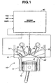
- the system includes an engine 10 having a plurality of cylinders each fed by fuel injectors 18.
- the fuel injectors 18 are shown receiving pressurized gasoline fuel from a supply 32 which is connected to one or more high or low pressure pumps (not shown) as is well known in the art.
- a high or low pressure pumps not shown
- embodiments of the present invention may employ a plurality of unit pumps (not shown), each pump supplying fuel to one of the injectors 18.
- engine 10 is a four-stroke cycle internal combustion engine capable of running under auto-ignition combustion of gasoline fuel and under spark-ignition combustion of gasoline fuel as well.
- the engine 10 includes a cylinder block 11 formed with a plurality of cylinders, only one being shown.
- a cylinder head 12 is attached to cylinder block 11 and closes the cylinders. As illustrated, each cylinder receives a reciprocating piston 13.
- the piston 13, cylinder and cylinder head 12 cooperate with each other to define a combustion chamber 8.
- the cylinder head 12 has two intake ports, only one being shown at 14, and two exhaust ports, only one being shown at 16, communicating with the combustion chamber.
- Intake and exhaust valves 15 and 17 are provided for admitting fresh air into the combustion chamber and for discharging exhaust gas from the combustion chamber, respectively.
- Two intake valves 15 close the two intake ports 14, respectively.
- Two exhaust valves 17 close the exhaust ports 16, respectively.
- the fuel injectors 18 are mounted to the cylinder head 12, each spraying fuel directly into the combustion chamber in one of the cylinders.
- the system 30 may also include various sensors 34 for generating a sensor signal indicative of a combustion event in one of the cylinders, and sensor signals indicative of corresponding operational conditions of engine 10 and other vehicular components.
- sensors 34 include a combustion event indicative (CEI) sensor 20, a crankshaft sensor and an accelerator pedal sensor.
- CEI sensor 20 generates a sensor signal indicative of a combustion event in one of the cylinders.
- CEI sensor 20 may be a pressure sensor, which detects cylinder pressure in one of the cylinders and generates a sensor signal indicative of variation of cylinder pressure due to combustion of charge in the cylinder.
- CEI sensor 20 may be a knock sensor, which detects cylinder vibration and generates a sensor signal indicative of an amplitude of cylinder vibration due to combustion of charge in the cylinder.
- the crankshaft sensor generates a position (POS) signal each time the crankshaft advances through a unit crank angle of 1 degree, and a reference (REF) signal each time the crankshaft advances a predetermined reference crank angle of 180 degrees in the case of four cylinders and 120 degrees in the case of six cylinders.
- the accelerator pedal sensor is coupled with a vehicle accelerator pedal 36 (see Figure2) through which the vehicle operator can express power or torque demand. Accelerator pedal 36 generates a vehicle accelerator pedal opening (VAPO) signal indicative of an opening angle or position of the accelerator pedal 36.
- VAPO vehicle accelerator pedal opening
- Controller 40 preferably includes a microprocessor 44 in communication with various computer readable storage media 46 via data and control bus 48.
- Computer readable storage media 46 may include any of a number of known devices, which function as a read-only memory (ROM) 50, random access memory (RAM), keep-alive memory (KAM) 54, and the like.
- the computer readable storage media 46 may be implemented by any of a number of known physical devices capable of storing data representing instructions executable by a computer such as controller 40.
- Known devices may include, but are not limited to, PROM, EPROM, EEPROM, flash memory, and the like in addition to magnetic, optical, and combination media capable of temporary or permanent data storage.
- Computer readable storage media 46 include various program instructions, software, and control logic to effect control of engine 10. Controller 40 receives signals from sensors 34 via. input ports 42 and generates output signals that are provided to fuel injectors 18 and spark plugs 56 via output ports 58.
- a logic unit (LU) 60 determines the type of ignition required: auto-ignition or spark-ignition, and determines the type of fuel injection required: split or single. Logic unit 60 may make such determination by rely on map shown in Figure 3 using current values of engine speed and load request. If split injection is required for auto-ignition, logic unit 60 adjusts operating variables governing a fuel injection system for creation of stratified charge in each of the cylinders. Referring to Figure 4, the operating variables include beginning of injection for first injection (BOI_F) I/T1, first pulse width for first injection (FPW_F) Pw1, beginning of injection for second injection (BOI_S) I/T2, and second pulse width for second injection (SPW_S) Pw2.
- the operating variables include beginning of injection for first injection (BOI_F) I/T1, first pulse width for first injection (FPW_F) Pw1, beginning of injection for second injection (BOI_S) I/T2, and second pulse width for second injection (SPW_S) Pw2.
- the second injection is carried out during compression stroke of piston, and the first injection precedes the first injection.
- BOI_F and FPW_F are determined such that the first injection is carried out after the completion of exhaust stroke of piston and before BOI_S.
- Logic unit 60 may be included in the functions of microprocessor 44, or may be implemented in any other inner known elements in the art of hardware and software control systems. It will be appreciated that logic unit 60 may be a part of controller 40 , or may be an independent control unit that is in communication with controller 40.
- control logic may be implemented in hardware, or a combination of hardware and software.
- the various functions are preferably carried out by a programmed microprocessor, but may include one or more functions implemented by dedicated electric, electronic, or integrated circuits.
- control logic may be implemented using any one of a number of known programming and processing techniques or strategies and is not limited to the order or sequence illustrated here for convenience. For example, interrupt or event driven processing is typically employed in real-time control applications, such as control of a vehicle engine. Likewise, parallel processing or multi-tasking systems may be used.
- the present invention is independent of the particular programming language, operating system, or processor used to implement the control logic illustrated.
- a functional block diagram illustrates a fuel delivery control for a split injection.
- Split injection is the delivering of fuel in two discrete quantities.
- a desired engine torque is determined based on various operating conditions such as engine speed (rpm), vehicle accelerator pedal opening (VAPO), and transmission ratio.
- Engine speed may be determined based on POS signal generated by the crankshaft sensor.
- Desired engine torque may be determined based on VAPO signal and engine speed.
- percent load could be used for the purpose of system control instead of engine torque.
- a desired total fuel quantity or fuel quantity per cycle 70 is determined based on the desired engine torque or the engine load. The desired total fuel quantity is divided into fuel quantity for first injection FQ_F 72 and fuel quantity for second injection FQ_S 74.
- the quantity of fuel for each injection is represented by a fuel pulse width.
- FPW 76 corresponds to the value of FQ_W 72
- SPW 78 corresponds to the value of FQ_S 74.
- Fuel injector control 80 initiates and terminates the first and second injections, and communicates with logic control 60 to control fuel injection.
- Logic unit 60 cooperates with fuel injector control to precisely control a beginning of each injection, BOI_F and BOI_S.
- an auto-ignition combustion range for part load is show as well as a spark ignition combustion range for full load.
- Logic unit 60 disables split injection and enables single injection for spark ignition combustion. If single injection is required, FQ_F 72 equals desired total fuel quantity 70, and FQ_S 74 equals zero.
- Logic unit 60 enables split injection and disables single injection for auto-ignition combustion.
- the auto-ignition combustion range is divided into an open control (or open loop control) section and a feedback control (or closed loop control) section. In open control section, control logic 60 adjusts operating variables governing split injection in response to operating conditions for creation of stratified charge to cause auto-ignition around top dead center (TDC) position of compression stroke of piston.
- TDC top dead center
- sensor signal from CEI sensor 20 is processed to determine an actual value of characteristic parameter representing combustion event of stratified charge in cylinder at block 82 (see Figure 5).
- Injection logic 84 modifies at least one of operating variables, namely, BOI_F I/TI, FPW_F Pw1, BOI_S I/T2, and SPW_S Pw2, in such a direction as to decrease a deviation between the actual value of the characteristic parameter and a target value thereof toward zero.
- CEI sensor 20 may be a pressure sensor to detect cylinder pressure in cylinder.
- a semiconductor pressure sensor may be used.
- a knock sensor may be used as CEI sensor 20. The knock sensor can detect cylinder vibration.
- CEI sensor 20 is a pressure sensor that generates a sensor signal indicative of cylinder pressure, and characteristic parameter is the maximum of cylinder pressure elevation rate dP/d ⁇ max , where P is cylinder pressure and ⁇ is crank angle. In another embodiment, characteristic parameter is the maximum of cylinder pressure P max . In further embodiment, characteristic parameter is a crank position at which cylinder pressure hits the maximum ⁇ P max . In still further embodiment, CEI sensor 20 is a pressure sensor that generates a sensor signal indicative of cylinder pressure, and characteristic parameter is amplitude of cylinder pressure. In still another embodiment, CEI sensor 20 is a knock sensor that generates a sensor signal indicative of cylinder vibration, and characteristic parameter is amplitude of cylinder vibration.
- FIG. 6 shows pressure diagram for auto-ignition combustion of homogeneous charge, illustrating four combustion events with different magnitudes of engine load from low load toward full load.
- Figure 7 shows heat diagram illustrating the four combustion events. Fuel quantity for injection is controlled to meet varying engine load request.
- Increasing fuel quantity to meet load request causes an increase in amount of heat generated by combustion. Besides, a drop in A/F causes an increase in chemical reaction speed between fuel and air, thereby to reduce period of combustion and advance beginning of generation of heat.
- Figure 8 provides a cylinder pressure diagram of one cycle of two-stage combustion
- Figures 9A, 9B, and 9C provide schematic cross sections of a cylinder, illustrating ignition of rich mixture portion, combustion of the rich mixture portion, and ignition of the surrounding lean mixture portion, respectively.
- Figure 10 is a pressure diagram illustrating a problem to be solved before accomplishing independent control of beginning of heat generation from load.
- variation of cylinder pressure due to two-stage combustion is illustrated over six consecutive combustion cycles.
- beginning of first-stage combustion which occurs around crank angle of 360°
- beginning of second-stage combustion which occurs around crank angle of 370° tend to move in one direction over the consecutive cycles. Accordingly, stable two-stage combustion cannot be expected within relatively high load range section of part load.
- Figure 11 illustrates a series of processes in combustion cycle, illustrating what causes a lack of stability in controlling beginning of second-stage combustion by adjusting stratification of mixture charge.
- Figures 12A to 12E illustrates split injection of gasoline during part load to create stratified charge for accomplishing two-stage combustion by auto-ignition.
- Figure 12A shows piston exhaust stroke
- Figure 128 shows an initial part of piston intake stroke.
- first injection of gasoline begins during piston intake stroke as shown in Figure 128.
- Gasoline fuel sprayed by first injection diffuses widely past BDC of piston intake stroke as shown in Figure 12C, thereby to create homogeneous relatively lean mixture during piston compression stroke as shown in Figure 12D.
- Second injection of gasoline begins during piston compression stroke as shown in Figure 12D.
- Gasoline fuel sprayed by second injection overlies a portion of the homogeneous relatively lean mixture, creating relatively rich mixture at the portion.
- BOI_S (Beginning Of Injection of Second injection) mainly determines volume of the relatively rich mixture portion. If BOI_S is advanced with respect to TDC of piston compression stroke, gasoline fuel sprayed by second injection diffuses widely until piston reaches TDC. If BOI_S is less advanced with respect to TDC position of piston compression stroke, gasoline fuel sprayed by second injection diffuses less widely until piston reaches TDC. Accordingly, volume of relatively rich mixture portion is less with less advanced BOI_S than volume of relatively rich mixture portion with advanced BOI_S.
- FQ_F Fluel Quantity for First injection
- FQ_S Fluel Quantity for Second injection
- BOI_S determine A/F of relatively rich mixture portion.
- A/F of relatively rich mixture portion determines beginning of first-stage combustion or beginning of auto-ignition of relatively rich mixture portion.
- Product of equivalence ratio of relatively rich mixture portion and volume thereof determines amount of heat generated by first-stage combustion.
- amount of heat generated by first-stage combustion and beginning of generation of heat by the first-stage combustion are determined as a function of operating variables BOI_F, FQ_F, BOI_S, and FQ_S of first and second injections.
- Figure 13 is a graphical representation of stratified charge created in cylinder by split injection of gasoline, first during intake stroke of piston, second during compression stroke of piston. Since gasoline is sprayed along the center axis of cylinder and diffused outwardly toward the cylinder wall, relatively rich mixture due to second injection is located around the cylinder axis and within relatively lean mixture due to first injection.
- the horizontal axis represents the diametrical distance from a portion of cylinder wall to the diametrically opposite portion thereof, while the vertical axis represents equivalence ratio.
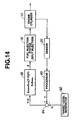
- Characteristic parameter Y includes (1) the maximum of cylinder pressure elevation rate dP/d ⁇ max , (2) the maximum of cylinder pressure P max , (3) crank position at which cylinder pressure hits the maximum ⁇ P max , and (4) amplitude of cylinder pressure fluctuation or cylinder vibration. Characteristic parameter Y is not limited to these examples and mat take any other variable representing combustion event timing. After completion of or during one cycle of combustion, sensor signal from sensor 20 indicative of combustion event timing is processed at block 90 to provide an actual value of characteristic parameter Y. A target level or value Yt of characteristic parameter Y may be found in a look-up table versus operating conditions. In Figure 14, the target value Yt of characteristic parameter Y is provided by a generator block 92.
- the reference character X generally designates at least one of operating variables governing fuel injection system capable of performing split injection.
- the governing operating variables include (1) BOI_F (Beginning Of Injection for First injection), (2) FQ_F (Fuel Quantity for First injection), (3) BOI_S (Beginning Of Injection for Second injection), and (4) FQ_S (Fuel Quantity for Second injection).
- the operating variables are not limited to these examples and may include any other variable, which has an influence of A/F or volume of relatively rich mixture.
- a split ratio between FQ_F and FQ_S may be regarded as one of such operating variables. Using the split ratio is advantageous in that A/F of relatively rich mixture can be varied without any variation in desired total fuel quantity that is determined by load request.
- Modifier block 96 provides, it the operating variable X as modified to fuel injection system 18. From the description, it will now be appreciated that A/F or volume of relatively rich mixture portion can be controllably varied by modifying at least one of governing operating variables in such a direction as to decrease a deviation Y - Yt toward zero.
- a method of the present invention for controlling auto-ignition combustion of gasoline in cylinder is generally designated at 100.
- operating variables governing a fuel injection system are adjusted for creation of stratified charge in cylinder.
- a sensor signal indicative of combustion event timing of the created stratified charge is input.
- an actual value of characteristic parameter representing combustion event timing in cylinder is determined from the sensor signal.
- at least one of the operating variables is modified in such a direction as to decrease a deviation between the actual value of the characteristic parameter and a target value thereof toward zero.
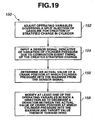
- a method of the present invention for controlling auto-ignition combustion of gasoline in cylinder is generally designated at 120.
- operating variables governing a split injection of gasoline are adjusted for creation of stratified charge in cylinder.
- a sensor signal indicative of combustion event timing of the created stratified charge is input.
- an actual value of characteristic parameter representing combustion event timing in cylinder is determined from the sensor signal.
- at least one of the operating variables is modified in such a direction as to decrease a deviation between the actual value of the characteristic parameter and a target value thereof toward zero.
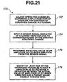
- a method of the present invention for controlling auto-ignition combustion of gasoline in cylinder is generally designated at 130.
- operating variables governing a split injection of gasoline are adjusted for creation of stratified charge in cylinder.
- a sensor signal indicative of variation of cylinder pressure due to combustion event timing of the created stratified charge is input.
- an actual value of the maximum of cylinder pressure elevation rate (dP/d ⁇ max ) is determined from the sensor signal.
- at least one of the operating variables is modified in such a direction as to decrease a deviation between the actual value of the maximum of cylinder pressure elevation rate and a target value thereof toward zero.
- a method of the present invention for controlling auto-ignition combustion of gasoline in cylinder is generally designated at 140.
- operating variables governing a split injection of gasoline are adjusted for creation of stratified charge in cylinder.
- a sensor signal indicative of variation of cylinder pressure due to combustion event timing of the created stratified charge is input.
- an actual value of the maximum of cylinder pressure P max is determined from the sensor signal.
- at least one of the operating variables is modified in such a direction as to decrease a deviation between the actual value of the maximum of cylinder pressure and a target value thereof toward zero.
- a method of the present invention for controlling auto-ignition combustion of gasoline in cylinder is generally designated at 150.
- operating variables governing a split injection of gasoline are adjusted for creation of stratified charge in cylinder.
- a sensor signal indicative of variation of cylinder pressure due to combustion event timing of the created stratified charge is input.
- an actual value of a crank position at which cylinder pressure hits the maximum ( ⁇ P max ) is determined from the sensor signal.
- at least one of the operating variables is modified in such a direction as to decrease a deviation between the actual value of crank position at which cylinder pressure hits the maximum and a target value thereof toward zero.
- a method of the present invention for controlling auto-ignition combustion of gasoline in cylinder is generally designated at 160.
- operating variables governing a split injection of gasoline are adjusted for creation of stratified charge in cylinder.
- a sensor signal indicative of variation of cylinder pressure due to combustion event timing of the created stratified charge is input.
- an actual value of amplitude of cylinder pressure fluctuation is determined from the sensor signal.
- at least one of the operating variables is modified in such a direction as to decrease a deviation between the actual value of amplitude of cylinder pressure fluctuation and a target value thereof toward zero.
- a method of the present invention for controlling auto-ignition combustion of gasoline in cylinder is generally designated at 170.
- operating variables governing a split injection of gasoline are adjusted for creation of stratified charge in cylinder.
- a sensor signal indicative of cylinder vibration due to combustion event timing of the created stratified charge is input.
- an actual value of amplitude of cylinder vibration is determined from the sensor signal.
- at least one of the operating variables is modified in such a direction as to decrease a deviation between the actual value of amplitude of cylinder vibration and a target value thereof toward zero.
- a control routine is generally indicated at 180.
- engine speed and load request are input.
- interrogation step 184 it is determined from the engine speed and load request whether or not the operating conditions allow auto-ignition combustion. In making this determination, a table look-up operation of combustion type map shown in Figure 3 may be performed. If the operating conditions fall outside of auto-ignition combustion range, the control logic goes to step 186. At step 186, spark-ignition combustion control is carried out. If, at step 184; it is determined that the operating conditions fall in auto-ignition combustion range, control logic goes to another interrogation step 188.
- step 188 it is determined whether or not operating conditions falls in feedback control range.
- the combustion type map shown in Figure 3 may be referred using engine speed and load request. If operating conditions falls outside of feedback control range and thus fall in open control range section of auto-ignition combustion range, control logic goes from step 188 to step 190.
- step 190 BOI_F I/T1, FPW_F Pw1, BOI_SI/T2, and SPW_S Pw2 are determined by performing table look-up operation of look-up table using engine speed and load request.
- step 192 BOI_F I/T1, FPW_FPw1, BOI_SI /T2, and SPW_S Pw2 are determined by performing table look-up operation of look-up table using engine speed and load request.
- step 194 cylinder pressure is input from sensor signal of sensor 20 (see Figure 14).
- step 196 an actual value of characteristic parameter Y is determined from cylinder pressure.
- interrogation step it is determined whether or not the actual value of characteristic parameter Y stays in acceptable controllable range in view of a target value of characteristic parameter Yt. If this is not the case, control logic returns to step 194.
- control logic goes to step 200.
- a target value of characteristic parameter Yt is determined by referring to look-up table using engine speed and load request.
- operating variable X is modified by calculating equations 1 and 2 involving as a deviation Y - Yt as a variable.
- engine speed and load request are input.
- it is determined whether operating condition falls in feedback control range section by referring to combustion type map shown in Figure 3 using engine speed and load request.
- Figure 23 is a graphical representation similar to Figure 13, illustrating influence of modification of second pulse width Pw2 on A/F of relatively rich mixture in cylinder.
- Figure 24 is a graphical representation similar to Figure 13, illustrating influence of modification of beginning of second injection I/T2 on A/F and volume of relatively rich mixture in cylinder.
- Figure 25 is a graphical representation similar to Figure 13, illustrating influence of modification of first pulse width Pw1 on A/F of relatively rich mixture and A/F of relatively lean mixture in cylinder.
- Figure 26 is a graphical representation similar to Figure 13, illustrating influence of modification of first pulse width Pw1 and modification of beginning of first injection I/T2 on A/F of relatively rich mixture and A/F and volume of relatively lean mixture in cylinder.
- Figure 27 is a table illustrating in what direction operating variables X are to be modified if characteristic parameter Y is greater than a target value (TARGET).
Landscapes
- Engineering & Computer Science (AREA)
- Chemical & Material Sciences (AREA)
- Combustion & Propulsion (AREA)
- Mechanical Engineering (AREA)
- General Engineering & Computer Science (AREA)
- Electrical Control Of Air Or Fuel Supplied To Internal-Combustion Engine (AREA)
- Combined Controls Of Internal Combustion Engines (AREA)
- Combustion Methods Of Internal-Combustion Engines (AREA)
- Electrical Control Of Ignition Timing (AREA)
Claims (17)
- Moteur à combustion interne et à auto-allumage (10) capable de fonctionner avec une combustion d'essence par auto-allumage et avec une combustion d'essence par allumage par étincelle, comprenant:au moins un cylindre;un système d'injection de carburant effectuant une injection d'essence pendant un cycle afin de créer une charge stratifiée dans le cylindre, dans lequel la charge stratifiée créée dans le cylindre comprend une partie de mélange air/carburant riche dans une partie restante de mélange air/carburant pauvre, la partie de mélange air/carburant riche étant suffisamment riche pour brûler par auto-allumage à un point d'allumage, provoquant une augmentation de la température et de la pression, qui déclenche un auto-allumage de la partie restante de mélange air/carburant pauvre; etun contrôleur de moteur (40),
dans lequel un capteur (20) est prévu afin de générer un signal de capteur indiquant le moment d'un évènement de combustion (CEI) de la charge stratifiée créée dans le cylindre; et ledit contrôleur de moteur (40) est adapté pour déterminer une valeur réelle d'un paramètre caractéristique (Y) représentant le moment d'un évènement de combustion de la partie restante de mélange air/carburant pauvre à partir du signal de capteur, et pour modifier au moins l'une des variables opérationnelles régissant l'injection destinée à un cycle suivant de façon à réduire un écart entre la valeur réelle du paramètre caractéristique (Y) représentant l'évènement de combustion et une valeur cible (Yt) de celui-ci, vers zéro. - Moteur à combustion interne et à auto-allumage (10) selon la revendication 1, dans lequel l'injection est une injection par division.
- Moteur à combustion interne et à auto-allumage (10) selon la revendication 2, dans lequel l'injection par division comprend une première injection précédant une seconde injection pendant la course de compression d'un piston (13) situé dans le cylindre.
- Moteur à combustion interne et à auto-allumage (10) selon la revendication 3, dans lequel le capteur (20) est un capteur de pression destiné à détecter une pression de cylindre (P) dans le cylindre, et dans lequel le paramètre caractéristique (Y) est un maximum de la vitesse d'élévation de la pression du cylindre (dP/dθmax).
- Moteur à combustion interne et à auto-allumage (10) selon la revendication 3, dans lequel le capteur (20) est un capteur de pression destiné à détecter une pression de cylindre (P) dans le cylindre, et dans lequel le paramètre caractéristique (Y) est le maximum de la pression du cylindre (Pmax).
- Moteur à combustion interne et à auto-allumage (10) selon la revendication 3, dans lequel le capteur (20) est un capteur de pression destiné à détecter la pression de cylindre (P) dans le cylindre, et dans lequel le paramètre caractéristique (Y) est une position de vilebrequin dans laquelle la pression du cylindre atteint le maximum (θPmax).
- Moteur à combustion interne et à auto-allumage (10) selon la revendication 3, dans lequel le capteur (20) est un capteur de pression destiné à détecter la pression de cylindre (P) dans le cylindre, et dans lequel le paramètre caractéristique (Y) est une amplitude de la fluctuation de la pression du cylindre.
- Moteur à combustion interne et à auto-allumage (10) selon la revendication 3, dans lequel le capteur (20) est un capteur de détonation, et dans lequel le paramètre caractéristique (Y) est une amplitude de la vibration du cylindre.
- Moteur à combustion interne et à auto-allumage (10) selon la revendication 3, dans lequel les variables opérationnelles comprennent la quantité de carburant et le moment de chacune des première et seconde injections.
- Moteur à combustion interne et à auto-allumage (10) selon la revendication 3, dans lequel la variable opérationnelle est la quantité de carburant destinée à la seconde injection, et dans lequel le contrôleur de moteur (40) permet à la quantité de carburant de subir une réduction lorsque l'écart entre la valeur réelle du paramètre caractéristique et la valeur cible (Yt) de celui-ci demande un retard du moment de l'évènement de combustion.
- Moteur à combustion interne et à auto-allumage (10) selon la revendication 3, dans lequel la variable opérationnelle est le moment de la seconde injection, et dans lequel le contrôleur de moteur (40) permet au moment de subir une avancée lorsque l'écart entre la valeur réelle du paramètre caractéristique et la valeur cible (Yt) de celui-ci demande un retard du moment de l'évènement de combustion.
- Moteur à combustion interne et à auto-allumage (10) selon la revendication 3, dans lequel la variable opérationnelle est la quantité de carburant destinée à la première injection, et dans lequel le contrôleur de moteur (40) permet à la quantité de carburant de subir une réduction lorsque l'écart entre la valeur réelle du paramètre caractéristique et la valeur cible (Yt) de celui-ci demande un retard du moment de l'évènement de combustion.
- Moteur à combustion interne et à auto-allumage (10) selon la revendication 3, dans lequel la variable opérationnelle est le moment de la première injection, et dans lequel le contrôleur de moteur (40) permet au moment de subir une avancée lorsque l'écart entre la valeur réelle du paramètre caractéristique et la valeur cible (Yt) de celui-ci demande un retard du moment de l'évènement de combustion.
- Moteur à combustion interne et à auto-allumage (10) selon la revendication 3, dans lequel le contrôleur de moteur (40) détermine un total de quantités de carburant pour les première et seconde injections en fonction de la charge sur le moteur (10).
- Procédé de commande d'un moteur à combustion interne et à auto-allumage (10), capable de fonctionner avec une combustion d'essence par auto-allumage et avec une combustion d'essence par allumage par étincelle, et possédant au moins un cylindre et un piston (13) situé dans le cylindre, comprenant les étapes consistant à:effectuer une injection d'essence par division sur un cycle, afin de créer une charge stratifiée dans le cylindre, dans lequel la charge stratifiée créée dans le cylindre comprend une partie de mélange air/carburant riche dans une partie restante de mélange air/carburant pauvre, la partie de mélange air/carburant riche étant suffisamment riche pour brûler par auto-allumage à un point d'allumage, provoquant alors une augmentation de la température et de la pression, qui déclenche un auto-allumage de la partie restante de mélange air/carburant pauvre;générer un signal de capteur indiquant le moment d'évènement de combustion (CEI) de la charge stratifiée;établir une valeur cible d'un paramètre caractéristique (Y) représentant le moment d'évènement de combustion (CEI) dans le cylindre;déterminer une valeur réelle du paramètre caractéristique (Y) représentant le moment d'évènement de combustion (CEI) de la partie restante de mélange air/carburant pauvre, à partir du signal de capteur; etmodifier au moins l'une des variables opérationnelles régissant une injection par division d'un cycle suivant, de façon à réduire un écart entre la valeur réelle du paramètre caractéristique (Y) et la valeur cible (Yt) de celui-ci, vers zéro.
- Système (30) de commande d'un moteur à combustion interne et à auto-allumage (10), capable de fonctionner avec une combustion d'essence par auto-allumage et avec une combustion d'essence par allumage par étincelle, et possédant au moins un cylindre et un piston (13) situé dans le cylindre, comprenant:un moyen de réalisation d'une injection d'essence par division sur un cycle, afin de créer une charge stratifiée dans le cylindre, dans lequel la charge stratifiée créée dans le cylindre comprend une partie de mélange air/carburant riche dans une partie restante de mélange air/carburant pauvre, la partie de mélange air/carburant riche étant suffisamment riche pour brûler par auto-allumage à un point d'allumage, provoquant une augmentation de la température et de la pression, qui déclenche un auto-allumage de la partie restante de mélange air/carburant pauvre;un moyen de génération d'un signal de capteur indiquant le moment de l'évènement de combustion (CEI) de la charge stratifiée;un moyen de détermination d'une valeur réelle d'un paramètre caractéristique (Y) représentant le moment de l'évènement de combustion (CEI) de la partie restante de mélange air/carburant pauvre, à partir du signal de capteur; etun moyen de modification d'au moins une variable opérationnelle régissant une injection par division d' un cycle suivant, de façon à réduire un écart entre la valeur réelle du paramètre caractéristique (Y) et une valeur cible (Yt) de celui-ci, vers zéro.
- Support de stockage informatique (46) possédant des données représentant des instructions exécutables par un contrôleur de moteur (40) afin de commander un moteur à combustion interne et à auto-allumage (10), le moteur (10) étant capable de fonctionner avec une combustion d'essence par auto-allumage et avec une combustion d'essence par allumage par étincelle, et possédant au moins un cylindre et un piston (13) situé dans le cylindre, le support de stockage informatique (46) possédant:des instructions destinées à établir une valeur cible (Yt) d'un paramètre caractéristique (Y) représentant le moment de l'évènement de combustion (CEI) dans le cylindre, dans lequel la charge stratifiée créée dans le cylindre comprend une partie de mélange air/carburant riche dans une partie restante de mélange air/carburant pauvre, la partie de mélange air/carburant riche étant suffisamment riche pour brûler par auto-allumage à un point d'allumage, provoquant une augmentation de la température et de la pression, qui déclenche un auto-allumage de la partie restante de mélange air/carburant pauvre;la détermination d'une valeur réelle du paramètre caractéristique (Y) représentant le moment de l'évènement de combustion (CEI) de la partie restante de mélange air/carburant pauvre produite par une injection d'essence par division, destinée à un cycle, dans le cylindre; etla modification d'au moins une variable opérationnelle régissant une injection par division destinée à cycle suivant, de façon à réduire un écart entre la valeur réelle du paramètre caractéristique (Y) et la valeur cible (Yt) de celui-ci, vers zéro.
Applications Claiming Priority (2)
| Application Number | Priority Date | Filing Date | Title |
|---|---|---|---|
| JP2000143850A JP3760725B2 (ja) | 2000-05-16 | 2000-05-16 | 圧縮自己着火式ガソリン機関 |
| JP2000143850 | 2000-05-16 |
Publications (3)
| Publication Number | Publication Date |
|---|---|
| EP1164271A2 EP1164271A2 (fr) | 2001-12-19 |
| EP1164271A3 EP1164271A3 (fr) | 2003-10-01 |
| EP1164271B1 true EP1164271B1 (fr) | 2006-03-15 |
Family
ID=18650605
Family Applications (1)
| Application Number | Title | Priority Date | Filing Date |
|---|---|---|---|
| EP01111564A Expired - Lifetime EP1164271B1 (fr) | 2000-05-16 | 2001-05-11 | Commande de l'injection en deux temps pour un moteur à essence à auto-allumage |
Country Status (4)
| Country | Link |
|---|---|
| US (1) | US6659068B2 (fr) |
| EP (1) | EP1164271B1 (fr) |
| JP (1) | JP3760725B2 (fr) |
| DE (1) | DE60117886T2 (fr) |
Families Citing this family (83)
| Publication number | Priority date | Publication date | Assignee | Title |
|---|---|---|---|---|
| JP3988383B2 (ja) * | 2000-12-19 | 2007-10-10 | 日産自動車株式会社 | 自己着火式エンジン及びその制御装置 |
| GB0107774D0 (en) * | 2001-03-28 | 2001-05-16 | Ford Global Tech Inc | Fuel metering method for an engine operating with controlled auto-ignition |
| JP3964387B2 (ja) * | 2001-05-22 | 2007-08-22 | 株式会社日立製作所 | 圧縮着火式内燃機関の制御装置 |
| SE523733C2 (sv) * | 2001-11-30 | 2004-05-11 | Scania Cv Ab | Förfarande för bränsleinsprutning i en förbränningsmotor samt förbränningsmotor |
| DE10159017A1 (de) * | 2001-12-01 | 2003-06-18 | Bosch Gmbh Robert | Verfahren und Vorrichtung zur Steuerung einer Brennkraftmaschine |
| DE10159016A1 (de) * | 2001-12-01 | 2003-06-18 | Bosch Gmbh Robert | Verfahren und Vorrichtung zur Steuerung einer Brennkraftmaschine |
| EP1318288B1 (fr) * | 2001-12-06 | 2017-09-06 | Denso Corporation | Système d'injection de carburant pour moteur à combustion interne |
| DE50112871D1 (de) * | 2001-12-14 | 2007-09-27 | Ford Global Tech Llc | Brennkraftmaschine mit Direkteinspritzung |
| EP1321655A1 (fr) * | 2001-12-21 | 2003-06-25 | Ford Global Technologies, Inc., A subsidiary of Ford Motor Company | Procèdè pour determiner et reguler le point d'allumage dans un moteur à combustion interne |
| DE10233612B4 (de) * | 2002-07-24 | 2008-07-10 | Siemens Ag | Verfahren und Vorrichtung zum Steuern des Verbrennungsvorganges einer HCCI-Brennkraftmaschine |
| US7025042B2 (en) * | 2002-08-08 | 2006-04-11 | The United States Of America, As Represented By The Administrator Of The U.S. Environmental Protection Agency | Methods of operation for controlled temperature combustion engines using gasoline-like fuel, particularly multicylinder homogenous charge compression ignition (HCCI) engines |
| JP4086602B2 (ja) | 2002-09-17 | 2008-05-14 | 株式会社日立製作所 | 多気筒エンジンの制御装置及び制御方法 |
| GB0227668D0 (en) * | 2002-11-27 | 2003-01-08 | Ricardo Consulting Eng | Improved engine management |
| US6837212B2 (en) * | 2002-12-19 | 2005-01-04 | Caterpillar Inc. | Fuel allocation at idle or light engine load |
| JP4161789B2 (ja) | 2003-04-25 | 2008-10-08 | いすゞ自動車株式会社 | 燃料噴射制御装置 |
| US7133761B2 (en) * | 2003-06-30 | 2006-11-07 | Westport Research Inc. | Method and apparatus for controlling an internal combustion engine using accelerometers |
| US6983732B2 (en) * | 2003-07-01 | 2006-01-10 | General Motors Corporation | Injection strategy for operating a direct-injection controlled auto-ignition four-stroke internal combustion engine |
| DE10336606B4 (de) * | 2003-08-08 | 2007-01-25 | Siemens Ag | Stellverfahren und Stellvorrichtung für einen Aktor |
| DE102004033072A1 (de) * | 2004-01-07 | 2005-07-28 | Robert Bosch Gmbh | Verfahren und Vorrichtung zur Steuerung einer Brennkraftmaschine |
| DE102004001118B4 (de) | 2004-01-07 | 2018-08-23 | Robert Bosch Gmbh | Verfahren und Vorrichtung zur Steuerung einer Brennkraftmaschine |
| DE102004001119A1 (de) * | 2004-01-07 | 2005-08-18 | Robert Bosch Gmbh | Verfahren und Vorrichtung zur Steuerung einer Brennkraftmaschine |
| JP2005214041A (ja) * | 2004-01-28 | 2005-08-11 | Nissan Motor Co Ltd | 直噴火花点火式内燃機関の制御装置 |
| US6935304B1 (en) * | 2004-03-17 | 2005-08-30 | International Engine Intellectual Property Company, Llc | Increasing the duration of peak combustion pressure in cylinders of a diesel engine using fuel injection control strategies |
| JP4415876B2 (ja) * | 2004-07-22 | 2010-02-17 | トヨタ自動車株式会社 | 内燃機関の制御装置 |
| US7152559B2 (en) * | 2004-07-26 | 2006-12-26 | General Motors Corporation | Valve and fueling strategy for operating a controlled auto-ignition four-stroke internal combustion engine |
| US7150250B2 (en) * | 2004-07-26 | 2006-12-19 | General Motors Corporation | Valve and fueling strategy for operating a controlled auto-ignition four-stroke internal combustion engine |
| US7128047B2 (en) * | 2004-07-26 | 2006-10-31 | General Motors Corporation | Valve and fueling strategy for operating a controlled auto-ignition four-stroke internal combustion engine |
| JP4483684B2 (ja) * | 2005-04-28 | 2010-06-16 | 株式会社デンソー | 筒内噴射式内燃機関の燃料噴射制御装置 |
| US7201137B2 (en) * | 2005-07-11 | 2007-04-10 | Caterpillar Inc | Mixed mode control method and engine using same |
| JP4591300B2 (ja) * | 2005-09-29 | 2010-12-01 | マツダ株式会社 | 4サイクル火花点火式エンジン |
| US7367319B2 (en) * | 2005-11-16 | 2008-05-06 | Gm Global Technology Operations, Inc. | Method and apparatus to determine magnitude of combustion chamber deposits |
| US7739999B2 (en) * | 2005-11-23 | 2010-06-22 | Gm Global Technology Operations, Inc. | Method and apparatus to control combustion in a multi-cylinder homogeneous charge compression-ignition engine |
| US8132555B2 (en) | 2005-11-30 | 2012-03-13 | Ford Global Technologies, Llc | Event based engine control system and method |
| US8434431B2 (en) | 2005-11-30 | 2013-05-07 | Ford Global Technologies, Llc | Control for alcohol/water/gasoline injection |
| US7357101B2 (en) | 2005-11-30 | 2008-04-15 | Ford Global Technologies, Llc | Engine system for multi-fluid operation |
| US7406947B2 (en) | 2005-11-30 | 2008-08-05 | Ford Global Technologies, Llc | System and method for tip-in knock compensation |
| US7412966B2 (en) | 2005-11-30 | 2008-08-19 | Ford Global Technologies, Llc | Engine output control system and method |
| US7395786B2 (en) * | 2005-11-30 | 2008-07-08 | Ford Global Technologies, Llc | Warm up strategy for ethanol direct injection plus gasoline port fuel injection |
| US7255090B2 (en) * | 2005-12-15 | 2007-08-14 | Ford Global Technologies, Llc | Compression ignition engine with pressure-based combustion control |
| US7389751B2 (en) | 2006-03-17 | 2008-06-24 | Ford Global Technology, Llc | Control for knock suppression fluid separator in a motor vehicle |
| US8267074B2 (en) | 2006-03-17 | 2012-09-18 | Ford Global Technologies, Llc | Control for knock suppression fluid separator in a motor vehicle |
| US7578281B2 (en) | 2006-03-17 | 2009-08-25 | Ford Global Technologies, Llc | First and second spark plugs for improved combustion control |
| US7533651B2 (en) | 2006-03-17 | 2009-05-19 | Ford Global Technologies, Llc | System and method for reducing knock and preignition in an internal combustion engine |
| US7665452B2 (en) | 2006-03-17 | 2010-02-23 | Ford Global Technologies, Llc | First and second spark plugs for improved combustion control |
| US7933713B2 (en) | 2006-03-17 | 2011-04-26 | Ford Global Technologies, Llc | Control of peak engine output in an engine with a knock suppression fluid |
| US7681554B2 (en) | 2006-07-24 | 2010-03-23 | Ford Global Technologies, Llc | Approach for reducing injector fouling and thermal degradation for a multi-injector engine system |
| US7909019B2 (en) | 2006-08-11 | 2011-03-22 | Ford Global Technologies, Llc | Direct injection alcohol engine with boost and spark control |
| US7832370B2 (en) * | 2006-11-16 | 2010-11-16 | Gm Global Technology Operations, Inc. | Low-load operation extension of a homogeneous charge compression ignition engine |
| US7461628B2 (en) * | 2006-12-01 | 2008-12-09 | Ford Global Technologies, Llc | Multiple combustion mode engine using direct alcohol injection |
| JP4353256B2 (ja) * | 2007-02-15 | 2009-10-28 | 株式会社デンソー | 燃料噴射制御装置及び燃料噴射制御システム |
| US7822529B2 (en) * | 2007-03-06 | 2010-10-26 | Gm Global Technology Operations, Inc. | Method and apparatus for determining a parameter for normalized instantaneous heat release in an internal combustion engine |
| DE102007013119A1 (de) * | 2007-03-13 | 2008-09-18 | Fev Motorentechnik Gmbh | Einspritzverfahren und zugehörige Verbrennungskraftmaschine |
| JP4734292B2 (ja) * | 2007-05-31 | 2011-07-27 | 本田技研工業株式会社 | ノックセンサの配置 |
| US7971567B2 (en) | 2007-10-12 | 2011-07-05 | Ford Global Technologies, Llc | Directly injected internal combustion engine system |
| JP4836088B2 (ja) * | 2007-11-08 | 2011-12-14 | 日立オートモティブシステムズ株式会社 | 圧縮自己着火式内燃機関の制御装置および制御方法 |
| JP4793381B2 (ja) * | 2007-12-07 | 2011-10-12 | トヨタ自動車株式会社 | 内燃機関の燃料噴射制御装置 |
| US8118009B2 (en) | 2007-12-12 | 2012-02-21 | Ford Global Technologies, Llc | On-board fuel vapor separation for multi-fuel vehicle |
| US8550058B2 (en) | 2007-12-21 | 2013-10-08 | Ford Global Technologies, Llc | Fuel rail assembly including fuel separation membrane |
| DE102008004361A1 (de) | 2008-01-15 | 2009-07-16 | Robert Bosch Gmbh | Verfahren zur Regelung eines Verbrennungsmotors, Computerprogramm und Steuergerät |
| JP4602420B2 (ja) * | 2008-01-15 | 2010-12-22 | 株式会社日立製作所 | 多気筒エンジンの制御装置及び制御方法 |
| US8141356B2 (en) | 2008-01-16 | 2012-03-27 | Ford Global Technologies, Llc | Ethanol separation using air from turbo compressor |
| DE602008001606D1 (de) * | 2008-04-17 | 2010-08-05 | Bosch Gmbh Robert | Elektronische Pilotsteuereinheit und Verfahren zum Ableiten optimierter Verweistabellen |
| US7845315B2 (en) | 2008-05-08 | 2010-12-07 | Ford Global Technologies, Llc | On-board water addition for fuel separation system |
| JP5195466B2 (ja) * | 2009-01-29 | 2013-05-08 | 日産自動車株式会社 | ディーゼル機関の制御装置 |
| JP5493429B2 (ja) * | 2009-03-31 | 2014-05-14 | マツダ株式会社 | 直噴エンジン |
| DE102009051137A1 (de) * | 2009-06-26 | 2011-01-05 | Mtu Friedrichshafen Gmbh | Verfahren zum Betreiben eines Verbrennungsmotors |
| JP5783506B2 (ja) * | 2010-06-09 | 2015-09-24 | 国立研究開発法人海上技術安全研究所 | 多種燃料に対応可能な燃料噴射装置及び陸舶産業用内燃機関 |
| US8447496B2 (en) | 2010-09-17 | 2013-05-21 | Ford Global Technologies, Llc | Fuel-based injection control |
| FR2978803B1 (fr) * | 2011-08-05 | 2015-04-10 | Rhodia Operations | Dispositif de distribution d'un additif liquide dans un circuit de circulation de carburant pour un moteur a combustion interne, vehicule comportant un tel dispositif et procede d'utilisation dudit dispositif |
| JP5739799B2 (ja) * | 2011-12-27 | 2015-06-24 | 本田技研工業株式会社 | 圧縮着火内燃機関の制御装置 |
| DE102013221995A1 (de) * | 2013-10-29 | 2015-04-30 | Robert Bosch Gmbh | Verfahren und Vorrichtung zur Bewertung von anormalen Verbrennungen einer Brennkraftmaschine eines Kraftfahrzeuges durch eine Regressionsberechnung einer physikalischen Größe |
| US9803580B2 (en) * | 2014-07-16 | 2017-10-31 | GM Global Technology Operations LLC | Method and apparatus for controlling operation of an internal combustion engine |
| KR101826562B1 (ko) * | 2016-11-02 | 2018-02-07 | 현대자동차 주식회사 | 가솔린-디젤 혼합 연소 엔진의 제어 장치 및 방법 |
| US20180128200A1 (en) * | 2016-11-10 | 2018-05-10 | GM Global Technology Operations LLC | Systems and methods for controlling fluid injections |
| WO2018096590A1 (fr) * | 2016-11-22 | 2018-05-31 | マツダ株式会社 | Dispositif de commande pour moteur de type à auto-allumage par compression |
| WO2018097104A1 (fr) * | 2016-11-22 | 2018-05-31 | マツダ株式会社 | Dispositif de commande de moteur à auto-allumage par compression |
| WO2018096652A1 (fr) * | 2016-11-25 | 2018-05-31 | マツダ株式会社 | Dispositif de commande pour moteur à auto-allumage par compression |
| JP6583336B2 (ja) * | 2017-03-30 | 2019-10-02 | マツダ株式会社 | 圧縮自己着火式エンジンの制御装置 |
| US10895208B2 (en) * | 2017-08-24 | 2021-01-19 | Mazda Motor Corporation | Control system for compression-ignition engine |
| DE102018209252B4 (de) * | 2018-06-11 | 2020-06-18 | Bayerische Motoren Werke Aktiengesellschaft | Diagnose eines Ladungswechselverhaltens eines Verbrennungsmotors |
| FR3085723B1 (fr) * | 2018-09-07 | 2021-05-28 | Renault Sas | Procede de regulation de la combustion dans un moteur diesel a combustion homogene ou quasi-homogene |
| JP7468307B2 (ja) * | 2020-11-13 | 2024-04-16 | マツダ株式会社 | エンジンシステム |
| US20260015980A1 (en) * | 2024-07-09 | 2026-01-15 | Caterpillar Inc. | Systems and methods for controlling cylinder combustion in a dual fuel engine using in-cylinder pressure sensing |
Citations (1)
| Publication number | Priority date | Publication date | Assignee | Title |
|---|---|---|---|---|
| EP0686759A1 (fr) * | 1994-06-07 | 1995-12-13 | Toyota Jidosha Kabushiki Kaisha | Moteur à combustion à pétrole avec allumage par compression à injection du combustible dans le conduit d'admission pendant la course d'échappement |
Family Cites Families (12)
| Publication number | Priority date | Publication date | Assignee | Title |
|---|---|---|---|---|
| DE3641854A1 (de) * | 1986-12-08 | 1988-06-09 | Bundesrep Deutschland | Verfahren zum ausgleich des einflusses unterschiedlicher kraftstoffqualitaeten auf das betriebsverhalten eines dieselmotors |
| WO1990007644A1 (fr) * | 1988-12-24 | 1990-07-12 | Robert Bosch Gmbh | Regulation adaptative du martelement a l'acceleration |
| JPH0949452A (ja) * | 1995-08-08 | 1997-02-18 | Unisia Jecs Corp | 内燃機関の制御装置 |
| AU4082997A (en) * | 1996-08-23 | 1998-03-26 | Cummins Engine Company Inc. | Homogeneous charge compression ignition engine with optimal combustion control |
| JP3494832B2 (ja) * | 1996-12-18 | 2004-02-09 | トヨタ自動車株式会社 | 内燃機関の燃焼制御装置 |
| JPH10196424A (ja) | 1996-12-28 | 1998-07-28 | Toyota Central Res & Dev Lab Inc | 混合気の圧縮着火式燃焼方法および混合気の圧縮着火式ピストン内燃機関 |
| US6227151B1 (en) * | 1997-08-01 | 2001-05-08 | Ford Global Technologies, Inc. | Gasoline internal combustion engine |
| FR2768180B1 (fr) * | 1997-09-09 | 1999-10-08 | Inst Francais Du Petrole | Procede de fonctionnement d'un moteur 4 temps, en auto-allumage controle |
| JP3855481B2 (ja) * | 1998-08-12 | 2006-12-13 | 株式会社日立製作所 | エンジンの診断装置 |
| KR100341565B1 (ko) | 1998-11-11 | 2002-06-22 | 김윤 | 젖음성이 우수한 표면을 갖는 불소계 수지 |
| JP3835142B2 (ja) * | 1999-09-07 | 2006-10-18 | 日産自動車株式会社 | 自己着火・火花点火式内燃機関の制御装置 |
| US6401688B2 (en) | 2000-01-27 | 2002-06-11 | Nissan Motor Co., Ltd. | Auto-ignition combustion management in internal combustion engine |
-
2000
- 2000-05-16 JP JP2000143850A patent/JP3760725B2/ja not_active Expired - Fee Related
-
2001
- 2001-05-11 EP EP01111564A patent/EP1164271B1/fr not_active Expired - Lifetime
- 2001-05-11 DE DE60117886T patent/DE60117886T2/de not_active Expired - Lifetime
- 2001-05-14 US US09/853,704 patent/US6659068B2/en not_active Expired - Lifetime
Patent Citations (1)
| Publication number | Priority date | Publication date | Assignee | Title |
|---|---|---|---|---|
| EP0686759A1 (fr) * | 1994-06-07 | 1995-12-13 | Toyota Jidosha Kabushiki Kaisha | Moteur à combustion à pétrole avec allumage par compression à injection du combustible dans le conduit d'admission pendant la course d'échappement |
Also Published As
| Publication number | Publication date |
|---|---|
| EP1164271A2 (fr) | 2001-12-19 |
| JP2001323832A (ja) | 2001-11-22 |
| DE60117886D1 (de) | 2006-05-11 |
| US6659068B2 (en) | 2003-12-09 |
| EP1164271A3 (fr) | 2003-10-01 |
| US20010045200A1 (en) | 2001-11-29 |
| JP3760725B2 (ja) | 2006-03-29 |
| DE60117886T2 (de) | 2006-08-17 |
Similar Documents
| Publication | Publication Date | Title |
|---|---|---|
| EP1164271B1 (fr) | Commande de l'injection en deux temps pour un moteur à essence à auto-allumage | |
| US6609493B2 (en) | System and method for enhanced combustion control in an internal combustion engine | |
| US6619255B2 (en) | Combustion event indicative parameter dependent control for auto-ignited combustion | |
| US6718957B2 (en) | Intelligent control to stabilize auto-ignition combustion without rapid pressure increase | |
| US6508229B2 (en) | Auto-ignition combustion management in internal combustion engine | |
| CN100414085C (zh) | 内燃机的控制装置 | |
| CN101410609B (zh) | 喷油方法和相应的内燃机 | |
| US7966989B2 (en) | Engine control apparatus | |
| JP3404059B2 (ja) | 筒内直噴式エンジンの燃料噴射方法 | |
| EP1134400A2 (fr) | Gestion de combustion auto-allumée dans un moteur à combustion interne | |
| US7870844B2 (en) | Control system and method for internal combustion engine | |
| JPH051837U (ja) | 筒内直噴式エンジンの燃料噴射制御装置 | |
| EP1443197B1 (fr) | Système de commande pour l'injection directe de carburant | |
| US6470849B1 (en) | Separate injector main timing maps for use with and without pilot | |
| JPH0249939A (ja) | 2サイクル直噴エンジンの燃料噴射制御装置 | |
| JP3854209B2 (ja) | 内燃機関の燃料噴射制御装置 | |
| US20030041837A1 (en) | Method and system for operating a direct injection spark internal combustion engine having variable compression ratio modes | |
| RU2260141C2 (ru) | Способ управления работой многоцилиндрового двигателя внутреннего сгорания | |
| EP1164276B1 (fr) | Moteur à combustion interne avec support externe pour auto-allumage stable | |
| GB2256945A (en) | An idling r.p.m. control system for a two-stroke engine | |
| JP2004100557A (ja) | 内燃機関の燃料噴射制御装置 | |
| CN101326357A (zh) | 用于火花点火直喷式内燃机的控制设备以及控制方法 | |
| JP5064729B2 (ja) | 内燃機関の空気量算出装置 | |
| JPH05149168A (ja) | 筒内直噴式エンジンの燃圧制御装置 | |
| JP3084040B2 (ja) | 2サイクルエンジンの制御装置 |
Legal Events
| Date | Code | Title | Description |
|---|---|---|---|
| PUAI | Public reference made under article 153(3) epc to a published international application that has entered the european phase |
Free format text: ORIGINAL CODE: 0009012 |
|
| 17P | Request for examination filed |
Effective date: 20010511 |
|
| AK | Designated contracting states |
Kind code of ref document: A2 Designated state(s): AT BE CH CY DE DK ES FI FR GB GR IE IT LI LU MC NL PT SE TR |
|
| AX | Request for extension of the european patent |
Free format text: AL;LT;LV;MK;RO;SI |
|
| PUAL | Search report despatched |
Free format text: ORIGINAL CODE: 0009013 |
|
| AK | Designated contracting states |
Kind code of ref document: A3 Designated state(s): AT BE CH CY DE DK ES FI FR GB GR IE IT LI LU MC NL PT SE TR |
|
| AX | Request for extension of the european patent |
Extension state: AL LT LV MK RO SI |
|
| 17Q | First examination report despatched |
Effective date: 20031212 |
|
| AKX | Designation fees paid |
Designated state(s): DE FR GB |
|
| GRAP | Despatch of communication of intention to grant a patent |
Free format text: ORIGINAL CODE: EPIDOSNIGR1 |
|
| GRAS | Grant fee paid |
Free format text: ORIGINAL CODE: EPIDOSNIGR3 |
|
| GRAA | (expected) grant |
Free format text: ORIGINAL CODE: 0009210 |
|
| AK | Designated contracting states |
Kind code of ref document: B1 Designated state(s): DE FR GB |
|
| REG | Reference to a national code |
Ref country code: GB Ref legal event code: FG4D |
|
| REF | Corresponds to: |
Ref document number: 60117886 Country of ref document: DE Date of ref document: 20060511 Kind code of ref document: P |
|
| ET | Fr: translation filed | ||
| PLBE | No opposition filed within time limit |
Free format text: ORIGINAL CODE: 0009261 |
|
| STAA | Information on the status of an ep patent application or granted ep patent |
Free format text: STATUS: NO OPPOSITION FILED WITHIN TIME LIMIT |
|
| 26N | No opposition filed |
Effective date: 20061218 |
|
| REG | Reference to a national code |
Ref country code: FR Ref legal event code: PLFP Year of fee payment: 15 |
|
| PGFP | Annual fee paid to national office [announced via postgrant information from national office to epo] |
Ref country code: DE Payment date: 20150506 Year of fee payment: 15 Ref country code: GB Payment date: 20150506 Year of fee payment: 15 |
|
| PGFP | Annual fee paid to national office [announced via postgrant information from national office to epo] |
Ref country code: FR Payment date: 20150508 Year of fee payment: 15 |
|
| REG | Reference to a national code |
Ref country code: DE Ref legal event code: R119 Ref document number: 60117886 Country of ref document: DE |
|
| GBPC | Gb: european patent ceased through non-payment of renewal fee |
Effective date: 20160511 |
|
| REG | Reference to a national code |
Ref country code: FR Ref legal event code: ST Effective date: 20170131 |
|
| PG25 | Lapsed in a contracting state [announced via postgrant information from national office to epo] |
Ref country code: DE Free format text: LAPSE BECAUSE OF NON-PAYMENT OF DUE FEES Effective date: 20161201 Ref country code: FR Free format text: LAPSE BECAUSE OF NON-PAYMENT OF DUE FEES Effective date: 20160531 |
|
| PG25 | Lapsed in a contracting state [announced via postgrant information from national office to epo] |
Ref country code: GB Free format text: LAPSE BECAUSE OF NON-PAYMENT OF DUE FEES Effective date: 20160511 |