EP1808288A2 - Presse à balles - Google Patents
Presse à balles Download PDFInfo
- Publication number
- EP1808288A2 EP1808288A2 EP07008174A EP07008174A EP1808288A2 EP 1808288 A2 EP1808288 A2 EP 1808288A2 EP 07008174 A EP07008174 A EP 07008174A EP 07008174 A EP07008174 A EP 07008174A EP 1808288 A2 EP1808288 A2 EP 1808288A2
- Authority
- EP
- European Patent Office
- Prior art keywords
- front door
- bolt
- press
- baler
- baler according
- Prior art date
- Legal status (The legal status is an assumption and is not a legal conclusion. Google has not performed a legal analysis and makes no representation as to the accuracy of the status listed.)
- Withdrawn
Links
Images



Classifications
-
- B—PERFORMING OPERATIONS; TRANSPORTING
- B30—PRESSES
- B30B—PRESSES IN GENERAL
- B30B9/00—Presses specially adapted for particular purposes
- B30B9/30—Presses specially adapted for particular purposes for baling; Compression boxes therefor
- B30B9/3003—Details
- B30B9/3032—Press boxes
-
- B—PERFORMING OPERATIONS; TRANSPORTING
- B30—PRESSES
- B30B—PRESSES IN GENERAL
- B30B9/00—Presses specially adapted for particular purposes
- B30B9/30—Presses specially adapted for particular purposes for baling; Compression boxes therefor
- B30B9/3003—Details
- B30B9/3014—Ejection means
Definitions
- the invention relates to a baling press according to the preamble of claim 1 for compressing - compressing - in particular spent packaging materials or transport and / or storage containers, such as cardboard, films, PET bottles or the like articles and materials.
- the prior art discloses a variety of waste compactors of various designs for compacting spent packaging materials and other objects as well as a variety of methods and apparatus for manually or automatically setting bales of material pressed in these waste compactors.
- a waste press - a so-called vertical baler - with an ejector for the finished pressed bales known in the bottom of the press shaft of the waste press a pivotable lifting plate and a guided substantially in the rear wall, hinged with the lifting plate connected drawbar are provided.
- the drawbar is releasably connectable to the ejection of the finished material bale by means of a coupling part with the vertically movable pressure plate of the waste press, wherein the coupling part in depending on the position of the shaft of the press closing front door, mechanically positively coupled on or off.
- the front door rotatably mounted on a side wall of the shaft of the press is applied to the front edge (surface) of the opposite side wall and locked by a safety lock on the latter.
- a safety lock on the latter.
- Such safety closures are known in various designs, for example, a "handwheel adjusting spindle” closure of the DE 297 21 834 U1 or from the DE 195 45 766 A1 a swiveling "lever" lock in the lateral direction.
- the present invention seeks to improve the overall design of the baler so that on the one hand relief for the operator when opening the front door - baling door - or the press shaft door and / or the setting and ejection of the material bale are created and On the other hand, the security when opening and closing the baler door is increased, also the technical effort for the production of the baler should be kept low.
- the invention is based on a baling press, in particular a vertical baling press, for compacting (compressing) in particular spent packaging materials or transport and / or storage containers, such as cardboard boxes, foils, PET bottles or similar objects and materials
- a baling press for compacting (compressing) in particular spent packaging materials or transport and / or storage containers, such as cardboard boxes, foils, PET bottles or similar objects and materials
- the closed front door of the press housing is locked with a "lever" closure and / or which has an ejection device for the bale in the lower region of the shaft of the press, the so-called press shaft and / or at least at and / or into the shaft belonging and / or guided in the shaft parts of the press at least one means for guiding the binding material is provided.
- a basic idea of the invention is that the closure device for the front door is formed from a specially shaped bolt, which is arranged in particular pivotable on the side of the press housing and in whose recess a bolt of the front door can be latched.
- the closure device for the front door at least from the, in particular laterally, on the press housing pivotally mounted about a bearing, a slot-like guide and a handle having latch and the side of the front door in the corresponding area provided bolt is formed.
- the slot-like guide has at its end facing the bearing an upwardly directed recess and at its end facing the front door a substantially downwardly directed, passing into an exit recess.
- the front door-side end of the slot-like guide is formed by a downwardly inclined nose, the lower edge ends below the imaginary extension of the lower leading edge of the guide and preferably above the lower body edge of the bolt and at the same time is the outer boundary wall of the exit.
- the latch limit stop when unlocking the front door by lifting the bolt by means of a handle of the locking bolt along a leading edge of the guide of the bolt up to a trained as a nose, integrated into the latch limit stop is moved to the stop pin abuts, causing the on the front door acting expansion force of the pressed bale is intercepted. After a short dwell time, then the front door is fully opened in preparation for the ejection of the bale. For this is actuated by repeated operation of the handle of the pivotable about a bearing bolt and approximately simultaneous opening movement of the front door of the locking bolt under the raised nose away.
- the handle of the bolt is mounted in a hinge and at least in the closed position of the front door to the latter is pivotally.
- a preferred embodiment is that the arranged on one of the side walls of the press housing bearings of the bolt and provided on the relevant same side on the front door locking bolts, seen from the bottom of the baler from, lie approximately at the same height. It is also advantageous if the imaginary connecting line between the bearing and the locking pin is substantially a horizontal.
- An advantage of the subject invention also that at the front door above the locking bolt and the latter spaced another bolt is provided. In this case, the lower of the two bolts is designed as a locking pin movable in the slot-like guide and the upper of the two bolts as a securing pin. This securing pin limits the movement of the bolt in the upward direction, corresponding to the upper contour line of the bolt.
- the pressure plate guided in the shaft of the press on its rear side, so facing the rear wall of the press housing is provided with at least one projecting, in particular U-shaped web, wherein preferably the two legs of the U-shaped web end a latch are closed, so that an enclosed gap is formed, in which the binder for setting the finished pressed bale, preferably band, is feasible.
- the number of webs depends primarily on the number of intended strapping with binders, these are usually three to four strapping.
- baler is, inter alia, that for the task - to provide relief for the operator of a baler - partial solutions have been found that solve the task according to the user desired level of equipment of a baler, but also in common realization of a baler for the solution of the task.
- the U-shaped web projects into a groove provided in or on the rear wall, wherein this groove is formed in particular by mutually spaced, angled limbs of profile parts of the rear wall, or for example by being placed on the inner surface of the rear wall , preferably in pairs arranged strips, in particular moldings.
- the clear width of this groove is specially held so that the respective, provided on the back of the press plate web can move along in the vertical upward or downward movement of the press plate with enough play in this groove.
- This embodiment according to the further basic idea of the invention has the effect that no waste material can settle during the compression of the waste material into a bale in the said groove provided for the guidance of the binder.
- the supply of the binder takes place via a tube, whose lower portion is directed so that the binder is inevitably introduced into the gap of the web during insertion and pushing through the tube.
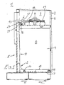
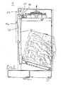
- FIGS 1 to 5 show a baler 1 with an ejector 2.
- the baler 1 consists of a Press housing 3, with a bottom surface 7, a rear wall 5, a front door 6 with an integrated filler flap, not shown, and side walls 4, and a surrounded by the press housing 3 shaft 34, with at least one pressing area 8 and an overlying filling area 9, and a arranged above the latter 9, not shown here in Figures 1 to 2a, known per se drive for the baler, which is connected to a movable plate 34 in the press plate 15.
- the ejector 2 consists of a lifting plate 10 which is rotatably mounted on the bottom surface 7 in the pressing region 8 of the shaft 34 by means of a bearing 11, a tie rod 12 with slider 12 a, which is preferably longitudinal - vertically - guided in the rear wall 5, with the Lifting plate 10 is hingedly connected by a hinge 14 and in the upper end region has a specially angled, projecting into the pressing portion 8 end 24, and arranged on the pressing plate entrainment of the temporary parts in the effective range of the end 24 of the tie rod 12 are pivoted ,
- a driver is provided which consists of a pawl 16 and a driving hook 17 and is pivoted to a basic position so that a movement of the pressing plate 15 can take place; the catch hook 17 is formed in particular L-shaped.
- the pivoting of the driving hook 17 in the ejection position takes place when the front door 6 is open by the movement of a guided Slider 18 via a handle member 19, while the slider 18 actuates the pawl sixteenth
- the pawl 16 and the catch hook 17 are mounted on a shaft 20 which is mounted in bearing blocks 21 and 22 which are mounted on the press plate 15.
- the slider 18 can be moved manually by actuating the grip element 19 in the direction of the rear wall 5 of the baler 1.
- the pawl 16 and the driving hook 17 are pivoted into a working position.
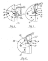
- FIGS. 6 to 9 show a new closure device, a latch 25 mounted on the press housing 3, which has a recess 26 in which a bolt 27 arranged on the front door 6 engages.
- a latch 25 mounted on the press housing 3 which has a recess 26 in which a bolt 27 arranged on the front door 6 engages.
- the latch 25 has an outer projection 37 which abuts on further lifting of the bolt 25 in this phase of the opening operation to a above the locking pin 27 arranged securing pin 36 and an unintentional, fast opening - popping of the bolt 25 by the still pressurized front door 6 - prevented.
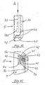
- FIGS. 10 and 11 Further details of the new baler relating to the above further basic concept of the invention are shown in FIGS. 10 and 11, relating to an improved (binder) tape guide.
- the pressure plate 40 provided there is provided at its rear side, that is to say the rear wall 5 of the press housing 3, with at least one projecting U-shaped web 41.
- the two legs of the U-shaped web 41 are closed by a bolt 42, so that an enclosed gap 43 is formed, in which the binder for setting the finished pressed bale, usually band, is performed.
- the web 41 moves in a in or on the rear wall. 5 provided groove 5b, said groove 5b of spaced-apart, angled legs 5a 'of profile parts 5a of the rear wall 5 is formed.
- this groove 5b is carried out as already described above. This provided in the rear wall 5 of the shaft of the press groove 5b, which is provided for receiving portions of the binding agent, so that the binder is not unnecessarily stressed during the pressing process, is now kept free by protruding into this groove web 41, so that the binder is not unnecessarily affected by waste material squeezed into the groove 5b during the pressing operation.
- the feeding of the strip takes place in particular via a tube 33, the lower portion 33 a is directed so that the tape when inserted and pushed through the tube 33 is inevitably inserted into the gap 43 of the web 41.
- the tube 33 can be fastened either to the rear wall 5 of the press housing 3, or to the supporting structure of the drive unit, not shown above the filling area 9, or to the press plate 40 itself.
- the supply of the binder, not shown, to the tube 33 is carried out in a known manner, either from arranged on the back of the press housing or arranged in the front, upper region of the press supply rollers.
- the equipment of the baler with one or more control units together with safety circuits or devices, Binder storage, binder tensioning means and the like units here does not relate to the subject invention and were therefore not further described.
- This equipment of the baler is at the discretion of the operator or manufacturer of the baler.
Landscapes
- Engineering & Computer Science (AREA)
- Mechanical Engineering (AREA)
- Auxiliary Devices For And Details Of Packaging Control (AREA)
- Refuse Collection And Transfer (AREA)
- Preliminary Treatment Of Fibers (AREA)
- Press Drives And Press Lines (AREA)
- Basic Packing Technique (AREA)
- Separation By Low-Temperature Treatments (AREA)
Applications Claiming Priority (2)
| Application Number | Priority Date | Filing Date | Title |
|---|---|---|---|
| DE10029979A DE10029979C2 (de) | 2000-06-26 | 2000-06-26 | Ballenpresse |
| EP01115369A EP1167005B1 (fr) | 2000-06-26 | 2001-06-26 | Presse à balles |
Related Parent Applications (1)
| Application Number | Title | Priority Date | Filing Date |
|---|---|---|---|
| EP01115369A Division EP1167005B1 (fr) | 2000-06-26 | 2001-06-26 | Presse à balles |
Publications (2)
| Publication Number | Publication Date |
|---|---|
| EP1808288A2 true EP1808288A2 (fr) | 2007-07-18 |
| EP1808288A3 EP1808288A3 (fr) | 2008-01-23 |
Family
ID=7646157
Family Applications (2)
| Application Number | Title | Priority Date | Filing Date |
|---|---|---|---|
| EP01115369A Expired - Lifetime EP1167005B1 (fr) | 2000-06-26 | 2001-06-26 | Presse à balles |
| EP07008174A Withdrawn EP1808288A3 (fr) | 2000-06-26 | 2001-06-26 | Presse à balles |
Family Applications Before (1)
| Application Number | Title | Priority Date | Filing Date |
|---|---|---|---|
| EP01115369A Expired - Lifetime EP1167005B1 (fr) | 2000-06-26 | 2001-06-26 | Presse à balles |
Country Status (4)
| Country | Link |
|---|---|
| EP (2) | EP1167005B1 (fr) |
| JP (1) | JP2002059296A (fr) |
| AT (1) | ATE368565T1 (fr) |
| DE (2) | DE10029979C2 (fr) |
Family Cites Families (16)
| Publication number | Priority date | Publication date | Assignee | Title |
|---|---|---|---|---|
| DE1165451B (de) * | 1961-03-22 | 1964-03-12 | Wilmot Breeden Ltd | Hauben- oder Deckelverschluss insbesondere fuer Kraftfahrzeuge |
| US3916781A (en) * | 1973-02-16 | 1975-11-04 | American Environmental Prod | Bale ejection system |
| US3910181A (en) * | 1974-01-04 | 1975-10-07 | Fremco Manufacturing Inc | Baling press |
| DE2630906A1 (de) * | 1976-07-09 | 1978-01-12 | Schleicher Co Feinwerktech | Pressvorrichtung |
| US4232599A (en) * | 1978-10-19 | 1980-11-11 | J. V. Manufacturing & Welding, Inc. | Waste paper compacter with front access features |
| GB2060480B (en) * | 1979-10-18 | 1983-06-22 | Schleicher Co Feinwerktech | Baling press |
| DE3606309A1 (de) * | 1986-02-27 | 1987-09-03 | Hermann Schwelling | Fanghaken fuer den bedienungshebel des frontseitigen tuerverschlusses an horizontal wirkenden ballenpressen |
| DE3907334A1 (de) * | 1989-03-08 | 1990-09-20 | Schleicher Co Feinwerktech | Verschlussvorrichtung fuer die tuer einer ballenpresse |
| US5062358A (en) * | 1989-09-11 | 1991-11-05 | Marcella M. Fox | Bale ejector for a trash compactor |
| DE4215639C2 (de) * | 1992-03-07 | 1996-05-02 | Bermatingen Maschf | Vorrichtung zur Arretierung einer Auswurfklappe für den Preßkasten einer Ballenpresse |
| DE4336437A1 (de) * | 1993-10-26 | 1995-04-27 | Bermatingen Maschf | Ballenpresse |
| EP0723857B1 (fr) * | 1994-12-27 | 1999-04-21 | Hermann Schwelling | Porte frontale de sécurité pour presses à balles |
| US5575199A (en) * | 1995-03-22 | 1996-11-19 | Yamamoto; Soichiro | Compactor |
| DE19738060A1 (de) * | 1997-09-01 | 1999-03-11 | Hermann Schwelling | Abfallpresse mit Auswurfeinrichtung für Ballen |
| DE29721834U1 (de) * | 1997-12-10 | 1998-04-09 | Schwelling, Hermann, 88682 Salem | Sicherheitsverschluß für die Preßschachttür von Abfall-Ballenpressen |
| DE19817807B4 (de) * | 1998-04-21 | 2012-06-28 | Hermann Schwelling | Schachttür für eine Ballenpresse und zugehörige Ballenpresse |
-
2000
- 2000-06-26 DE DE10029979A patent/DE10029979C2/de not_active Expired - Fee Related
-
2001
- 2001-06-26 DE DE50112780T patent/DE50112780D1/de not_active Expired - Fee Related
- 2001-06-26 AT AT01115369T patent/ATE368565T1/de not_active IP Right Cessation
- 2001-06-26 EP EP01115369A patent/EP1167005B1/fr not_active Expired - Lifetime
- 2001-06-26 JP JP2001192758A patent/JP2002059296A/ja active Pending
- 2001-06-26 EP EP07008174A patent/EP1808288A3/fr not_active Withdrawn
Also Published As
| Publication number | Publication date |
|---|---|
| DE50112780D1 (de) | 2007-09-13 |
| JP2002059296A (ja) | 2002-02-26 |
| DE10029979C2 (de) | 2003-11-06 |
| EP1167005A2 (fr) | 2002-01-02 |
| EP1167005A3 (fr) | 2003-07-23 |
| ATE368565T1 (de) | 2007-08-15 |
| DE10029979A1 (de) | 2002-01-17 |
| EP1167005B1 (fr) | 2007-08-01 |
| EP1808288A3 (fr) | 2008-01-23 |
Similar Documents
| Publication | Publication Date | Title |
|---|---|---|
| DE2358546C3 (de) | Vorrichtung zum Verpacken von Körpern aus zusammendrückbarem Material, beispielsweise aus Glasfasern bestehendem Isoliermaterial | |
| DE3509171A1 (de) | Vorrichtung zum kompaktieren von festen abfaellen | |
| EP3747643A2 (fr) | Dispositif d' alimentation de matière à presser pour une presse à balles verticale et presse à balles avec tel dispositif | |
| DE10251516B4 (de) | Ballenpresse | |
| EP2283999A2 (fr) | Presse à balles | |
| DE2344698B1 (de) | Vorrichtung zum Verdichten von Muell | |
| DE2942883A1 (de) | Vorrichtung zum selbsttaetigen verschliessen der unteren laschen einer rechteckigen schachtel mit faltlaschen und zum festhalten der schachtel in einer zum befuellen geeigneten stellung | |
| DE2839039A1 (de) | Vorrichtung zum ballenpressen von erntegut | |
| EP3453529B1 (fr) | Presse à coffre à balles pourvue de porte coulissante ainsi que procédé de fonctionnement d'une presse à coffre | |
| EP0899088B1 (fr) | Compacteur de déchets ayant un dispositif d'éjection de balles | |
| DE29919933U1 (de) | Vorrichtung zum Zusammenpressen von Abfall | |
| EP1167005B1 (fr) | Presse à balles | |
| DE1752244B2 (de) | Hydraulische Schrottschere mit einer den Schrott seitlich verdichtenden Sei tendruckpresse | |
| DE69404057T2 (de) | Verdichter | |
| DE69208084T2 (de) | Selbstdichtender Verschluss für einen flexiblen Behälter | |
| DE19738060A1 (de) | Abfallpresse mit Auswurfeinrichtung für Ballen | |
| DE4114893A1 (de) | Holzspaltvorrichtung mit hydraulisch betaetigbarem stempel | |
| DE9004989U1 (de) | Ballenpresse | |
| DE9412658U1 (de) | Vorrichtung zum Spalten von Holzstücken in einem Behälter | |
| DE838501C (de) | Pressform | |
| EP0596305B1 (fr) | Système de fermeture | |
| DE2258619C3 (de) | Müllpresse | |
| DE8912268U1 (de) | Container mit Räumschild | |
| DE20010786U1 (de) | Ballenpresse | |
| DE9218398U1 (de) | Verschlußvorrichtung |
Legal Events
| Date | Code | Title | Description |
|---|---|---|---|
| PUAI | Public reference made under article 153(3) epc to a published international application that has entered the european phase |
Free format text: ORIGINAL CODE: 0009012 |
|
| AC | Divisional application: reference to earlier application |
Ref document number: 1167005 Country of ref document: EP Kind code of ref document: P |
|
| AK | Designated contracting states |
Kind code of ref document: A2 Designated state(s): AT BE CH CY DE DK ES FI FR GB GR IE IT LI LU MC NL PT SE TR |
|
| AX | Request for extension of the european patent |
Extension state: AL LT LV MK RO SI |
|
| PUAL | Search report despatched |
Free format text: ORIGINAL CODE: 0009013 |
|
| AK | Designated contracting states |
Kind code of ref document: A3 Designated state(s): AT BE CH CY DE DK ES FI FR GB GR IE IT LI LU MC NL PT SE TR |
|
| AX | Request for extension of the european patent |
Extension state: AL LT LV MK RO SI |
|
| AKX | Designation fees paid | ||
| STAA | Information on the status of an ep patent application or granted ep patent |
Free format text: STATUS: THE APPLICATION IS DEEMED TO BE WITHDRAWN |
|
| 18D | Application deemed to be withdrawn |
Effective date: 20080724 |
|
| REG | Reference to a national code |
Ref country code: DE Ref legal event code: 8566 |