EP1176801A2 - Bildverarbeitungsvorrichtung, -verfahren, -programm und Speichermedium zum Speichern eines Bildverarbeitungsprogramms - Google Patents
Bildverarbeitungsvorrichtung, -verfahren, -programm und Speichermedium zum Speichern eines Bildverarbeitungsprogramms Download PDFInfo
- Publication number
- EP1176801A2 EP1176801A2 EP01117944A EP01117944A EP1176801A2 EP 1176801 A2 EP1176801 A2 EP 1176801A2 EP 01117944 A EP01117944 A EP 01117944A EP 01117944 A EP01117944 A EP 01117944A EP 1176801 A2 EP1176801 A2 EP 1176801A2
- Authority
- EP
- European Patent Office
- Prior art keywords
- data
- luminosity
- smoothing
- chromaticity
- image
- Prior art date
- Legal status (The legal status is an assumption and is not a legal conclusion. Google has not performed a legal analysis and makes no representation as to the accuracy of the status listed.)
- Granted
Links
Images



Classifications
-
- H—ELECTRICITY
- H04—ELECTRIC COMMUNICATION TECHNIQUE
- H04N—PICTORIAL COMMUNICATION, e.g. TELEVISION
- H04N1/00—Scanning, transmission or reproduction of documents or the like, e.g. facsimile transmission; Details thereof
- H04N1/46—Colour picture communication systems
- H04N1/56—Processing of colour picture signals
- H04N1/58—Edge or detail enhancement; Noise or error suppression, e.g. colour misregistration correction
-
- H—ELECTRICITY
- H04—ELECTRIC COMMUNICATION TECHNIQUE
- H04N—PICTORIAL COMMUNICATION, e.g. TELEVISION
- H04N1/00—Scanning, transmission or reproduction of documents or the like, e.g. facsimile transmission; Details thereof
- H04N1/40—Picture signal circuits
- H04N1/409—Edge or detail enhancement; Noise or error suppression
- H04N1/4092—Edge or detail enhancement
Definitions
- the present invention is relates an image processing method, an image processing device to carry out the image processing method, and a recording medium to record a program implementing the image processing method, whereby the quality of an image produced on photosensitive material from digital image data is improved by reducing particle noise that cause a coarse look of the image without blurring edges in the image.
- photographs have been printed by analog exposure whereby light is projected onto a photographic film recording an original image thereon, so that the light having passed through that photographic film illuminates photographic printing paper.
- Another popular method in recent years is digital exposure whereby monochromatic red, green, and blue lights are projected on each pixel on photographic printing paper for printing on the basis of digital image data obtained by scanning an image on a photographic film with a scanner or the like or by taking photographs with a digital camera, etc.
- the pixel density of an image printed on photographic printing paper is dictated by the resolution of the scanner and that of the exposure head. Particles forming an image on a positive film have a typical density of about 2500 dpi.
- Digital-exposure photographic printing devices are already introduced to the market with the same level of resolution as the particle density. The digital-exposure photographic printing device is capable of acquiring an image having the same level of resolution as the particle density of a film and printing on photographic printing paper images that are no inferior to those printed by analog exposure.
- particle density of 2500 dpi is equivalent to 3445 ⁇ 2362 pixels on a 135F-size (3.6 cm ⁇ 2.4 cm) photographic film.
- the photographic printing device for carrying out digital exposure can process image data and produces on the image such various special effects that analogexposure photographic printing device cannot produce.
- One of the special effects is sharpening whereby images (for example, those of people in the background and of facial features of a person) have prominent edges. In the following description, more details will be given as to sharpening.
- Sharpening is a process to form clear boundaries, i.e., edges, between adjacent objects in an image.
- a set of data termed a spatial filter, is used on image data to convert the image data in such a manner to impart large luminosity differences to target pixels constituting an edge and their adjacent pixels.
- a spatial filter is used on image data to convert the image data in such a manner to impart large luminosity differences to target pixels constituting an edge and their adjacent pixels.
- a 3 ⁇ 3 spatial filter is expressed as a 3 ⁇ 3 array, for example, 0 -1 0 -1 5 -1 0 -1 0 where each element represents a coefficient applied to the luminosity of one of the 3 ⁇ 3 pixels.
- the middle value, 5 is the element applied to the target pixel, and the other values are those applied to the adjacent pixels of the target pixel.
- the 3 ⁇ 3 filter is basically devised so that its elements add up to 1.
- a 100 ⁇ 100 pixel image is subjected to the 3 ⁇ 3 filter 10000 times, with a different pixel chosen as the target pixel each time, to sharpen the whole image.
- Multiplying the elements of the 3 ⁇ 3 filter array and the associated elements of the 3 ⁇ 3 pixel array, element by element, is equivalent to applying the filter to the pixels.
- the filtered luminosities of the pixels are represented by a 3 ⁇ 3 array, 0 -49 0 -52 250 -49 0 -51 0 Since the values of the filtered luminosity add up to 49, the value, 50, of the target pixel is now set to 49. It would be understood from this example that the filtering hardly changes luminosity in the monotonous part of the image.
- the luminosities of 3 ⁇ 3 pixels on an edge of the object are represented by a 3 ⁇ 3 array, for example, 10 30 70 15 50 90 20 80 85 At this part of the edge, values are low near the upper left corner and high near the lower right corner.
- Applying the 3 ⁇ 3 filter to the 3 ⁇ 3 pixels we obtain 0 -30 0 -15 250 -90 0 -80 0 Since the values of the filtered luminosity add up to 35, the value, 50, of the target pixel is now set to 35.
- the luminosities of the 3 ⁇ 3 pixels are represented by a 3 ⁇ 3 array, for example, 30 70 85 50 90 95 80 85 90
- Figures 11 (a), 11(b) illustrate the image data at the edge part before and after the filtering.
- the illustration tells that sharpening is a process to add a spike-like amplification in Figure 11(b) to the original contrast in Figure 11(a) at an edge to enhance the contrast at the edge.
- the spatial filter when used in processing image data, hardly changes the image data in monotonous parts of the image, but increases luminosity differences at edges. Subjecting all the pixels of the image to this process enhances the sharpness of the whole image.
- the aforementioned high resolution digital-exposure photographic printing device is capable or acquiring an image having practically the same level of resolution as the particle density of a film.
- a photograph, if printed on the same scale as the photographic film, is made of pixels, each as large as a film particle.
- the film particles share among them very similar, but not completely identical, coloring properties and cause fine variations in chromaticity and luminosity.
- the "noise" occurring in the film particle level (hereinafter, will be referred to film particle noises) is passed on in the course of printing, causing a coarse look of the printed photograph.
- the conventional sharpening method exacerbates particulate nature of the photographic film, as well as enhances edges in an image, imparting a more coarse look to the image printed on photographic printing paper.
- the resultant image may look very ugly. Image quality degrades, especially, if human skin gives a rough look.
- blurring that is, a repeated process of replacing a value of a target pixel with a mean value of its surrounding pixels until the process covers the whole image.
- the blurring process goes too far and blurs edges which are exactly where we wanted to increase sharpness in the first place.
- a possible alternative is to implement a blurring process on acquired image data before sharpening. In this case, however, the image will be stripped of its minute details.
- the present invention has an objective to provide an image processing method, an image processing device to carry out the image processing method, an image processing program to implement the image processing method, and a recording medium to record the image processing program, all for use to produce an image on photosensitive material from digital image data, whereby the produced image has less of a coarse look caused by film particles and has no edges blurred.
- an image processing method in accordance with the present invention is characterized in that it includes the steps of:
- Film particle noise contains fine chromaticity variations and fine luminosity variations, i.e., chromaticity noise and luminosity noise.
- chromaticity noise removal and luminosity noise removal can be carried out at different rates to achieve optimum noise removal: for example, chromaticity noise removal is carried out at a relatively high rate where chromaticity noise is distinctly visible, and luminosity noise removal is carried out at a relatively low rate where luminosity noise is distinctly visible.
- chromaticity variations and luminosity variations are either very small or practically ignorable in monotonous parts of the image and relatively large at edges in the image; the latter variations are particularly large at edges. Therefore, luminosity data contains more edge information of the image than does chromaticity data. This is another reason why it is preferable to carry out chromaticity noise removal and luminosity noise removal at different rates.
- neither luminosity noise removal nor chromaticity noise removal is carried out at the edges. More preferably, since more edge information is found in the luminosity data than in the chromaticity data, the rate of luminosity noise removal should be lowered gradually to 0, but more quickly than the chromaticity noise removal, as moving from monotonous parts toward edges in the imace.
- the chromaticity noise removal does not as much attenuate edge information as the luminosity noise removal and therefore better reduces the coarse look of the image when carried out up to quite near the edges.
- the foregoing method whereby the rates of smoothing of the chromaticity data and of smoothing of the luminosity data are changed according to a variation of the luminosity data in two-dimensional coordinate space, can strike the best balance between the chromaticity noise removal by means of smoothing of the chromaticity data and the luminosity noise removal by means of smoothing of the luminosity data and produce satisfactory results in both the retainment of the edges in the image and the elimination of the coarse look of the image.
- an image processing device in accordance with the present invention is characterized in that it includes:
- the smoothing rate computing section computes well-balanced rates of the smoothing of the chromaticity data and the smoothing of the luminosity data for each unit area of the image and therefore effectively reduces the coarse look of the image without blurring the edges.
- the chromaticity noise removing section receives chromaticity data from the data separator section and the rate of chromaticity noise removal from the smooching rate computing section to smooth the chromaticity data for each unit area of the image.
- the luminosity noise removing section receives luminosity data from the data separator section and the rate of luminosity noise removal from the smoothing rate computing section to smooth the luminosity data for each unit area of the image.
- the image has its quality greatly enhanced wich better contrast, less of the coarse look, and retained sharpness of the edges.
- the human eye is more sensitive to luminosity variations than to chromaticity variations.
- a combination of powerful chromaticity-noise-removing blurring (smoothing) and soft luminosity- noise-removing blurring (smoothing) removes much of the noise and retains clear edges. Understanding these characteristics of the eye provided the basis for the first insight that led us successfully to the present invention.
- luminosity variations are more visible than chromaticity variations.
- luminosity data contains more edge information than does chromaticity data and that the edge information is effectively retained if the blurring applied to luminosity data is restrained relatively to the blurring applied to the chromaticity data.
- an image processing method in accordance with the present invention, whereby film particle noise in an image data output from a scanner reading a developed photographic film is reduced by separating the image data into luminosity data and chromaticity data and applying blurring to the chromaticity data and the luminosity data with thoroughness that is varied according to variations of luminosity data in two-dimensional coordinate space.
- the image processing device is configured in accordance with the present invention so that it can print an image on photographic printing paper (photosensitive material) by illuminating the photographic printing paper according to, for example, BGR image data.
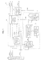
- the image processing device has an imaging section 1, an image processing section 4 with a blurring section 2 and a sharpening section 3, and an exposure section 5.
- the imaging section 1 is a scanner scanning an image (hereinafter, will be alternatively referred to as an original image in some cases) stored on a negative film by measuring light passing through the negative film, and is configured including, for example, a light source shining light onto the negative film, BGR color filters, and a CCD camera including either a single CCD (Charge-Coupled Device) or three CCDs.
- a light source shining light onto the negative film
- BGR color filters and a CCD camera including either a single CCD (Charge-Coupled Device) or three CCDs.
- the imaging section 1 transfers electric signals to the image processing section 4 according to the BGR components of the incoming light.
- a set of image data is thus obtained which is representative of the chromaticity and luminosity of pixels forming the original image for each of the BGR colors.
- the image processing section 4 implements various kinds of image processing on the BGR sets of image data transferred from the imaging section 1, including noise removal, sharpening, compensation for irregularity in the imaging by the CCDs and in the exposure by the exposure head, gamma correction in view of the coloring properties of the photographic printing paper, etc.
- the image processing section 4 may be provided inside the image processing device as a microprocessor and/or DSP (digital signal processor) or outside the image processing device as a PC (personal computer).
- the image processing section 4 further includes a memory (not shown) temporarily storing the image data from the imaging section 1 and a control section (not shown) controlling the exposure operation of the exposure section 5.
- the blurring section 2 provided in the image processing section 4, includes a structure to separate the image data into luminosity data and chromaticity data and change the thoroughness of the blurring applied to the chromaticity data and of the blurring applied to the luminosity data according to the variations of the luminosity data in two-dimensional coordinate space. More details will be given later about the image processing section 4.
- the sharpening section 3, provided in the image processing section 4, is responsive to an instruction of the operator and where necessary to produce an image with sharp edges, implements sharpening on the image data from which the chromaticity and luminosity noise has been removed by the blurring section 2.
- the image data output from the imaging section 1 may be fed first to the sharpening section 3 for sharpening and then to the blurring section 2 for noise removal. No matter which process is implemented first, the resultant image has better quality than conventional images.
- the exposure section 5 controls exposure (inclusive of no exposure) of photographic printing paper for each pixel according the BGR sets of image data supplied from the image processing section 4 to print an image on the photographic printing paper.
- means to control light exposure include PLZT exposure heads, DMDs (digital micromirror devices), LCDs (liquid crystal displays), LEDs (light emitting diode) panels, lasers, FOCRTs (fiber optic cathode ray tubes), and CRTs (cathodes ray tube). Needless to say, there must be provided a separate light source to the PLZT exposure head, DMD, LCD and other control means that does not emit light by itself.
- a rotary BGR filter, as well as a printing and other light-focus lenses, are also disposed for each color where necessary.
- PLZT is a (Pb 1-x La x )(Zr y Ti 1-y ) 1-x/4 O 3 solid solution which is obtained by making a solid solution (PZT) of lead zirconate (PbZrO 3 ) and lead titanate (PbTiO 3 ) of a suitable ratio and adding lanthanum before subjecting it to hot-pressing.
- PZT solid solution
- PbZrO 3 lead zirconate
- PbTiO 3 lead titanate
- PLZT can control light transmission when used in combination with a polarizer in the presence of an electric field.
- the image processing device of the present embodiment has a 2157 dpi resolution and is capable of acquiring an image having practically the same level of resolution as the particle density of the film and printing an image on photographic printing paper.
- the blurring section 2 is made of three major components: a Y/C separator section (data separator section) 6, a noise-removing-rate computing section (smoothing rate computing section) 7, and a noise removing section 8.
- the Y/C separator section 6 is a block converting the BGR sets of image data supplied from the imaging section 1 to YCC data.
- the Y/C separator section 6 converts the BGR sets of image data to a combination of luminosity data YY xy and chromaticity data BY xy , RY xy .
- Characters x, y in subscript position in YY xy , BY xy ,, and RY xy are a two-dimensional coordinate notation for pixels in a CCD in the imaging section 1.
- the noise-removing-rate computing section 7 computes variations of the luminosity data YY xy in two-dimensional coordinate space, or in other words, how the luminosity data YY xy varies between different parts of an image. Then, on the basis of the variations, it further computes rates of the blurring to be applied to the chromaticity data BY xy , RY xy and of the blurring to be applied to the luminosity data YY xy for each unit area in the image. The rates are output to the noise removing section 8.
- the noise-removing-rate computing section 7 discriminates between edges and other places in the image on the basis of the variations of the luminosity data YY xy , so as to implement no blurring at the edges and specify the rate of the blurring for the chromaticity data BY xy , RY xy greater than the rate of the blurring for the luminosity data YY xy at the other places.
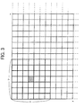
- Figure 3 shows an example of the design of unit areas, where the image is divided into square unit areas each made up of 7 ⁇ 7 pixels with a target pixel in the middle. Blurring is implemented for each unit area across the entire image.
- the unit area is designed large enough to enclose a sufficient number of pixels to reproduce the luminosity and chromaticity of the original image for reasons laid out immediately below.
- Blurring is a process of smoothing, i.e., entirely or partially replacing the chromaticity data BY xy , RY xy and the luminosity data YY xy of a target pixel with mean values of the data over the unit area including that target pixel.
- this process entirely or partially replaces the noise data with a mean value over the unit area, effectively reducing the noise.
- Noise is located irregularly; however, if a very small unit area (hence very few pixels) includes noise in it, the resulting mean data is strongly affected by the noise. Conversely, if a very large unit area (hence very many pixels) includes noise in it, the resulting mean data is affected by two or more different noise pixels.
- Noise in general is abnormality in luminosity and chromaticity that either recurs (for example, stripes) or occurs in a pixel out of sudden.
- the noise that we would like to reduce in the present invention is film particle noise caused by non-uniform distribution of coloring properties of film particles.
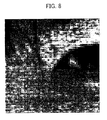
- Figure 8 shows film particle noise as an example, showing a part of the output image in Figure 5 which is reproduced from the image data acquired by the imaging section 1 directly without subjecting it to any blurring process. To produce this image, the image data acquired by the imaging section 1 is enlarged and cropped near the inner end of the left eye.
- film particle noise is visible on the skin as fine, particulate variations of luminosities. Film particle noise of this form appears as a coarse look across the entire image in Figure 5.
- the noise-removing-rate computing section 7 includes a distribution parameter computing section 9, a chromaticity-noise-removing-rate computing section 10, a luminosity-noise-removing-rate computing section 11, and a reference specification section 12.
- the distribution parameter computing section 9 computes a distribution parameter DP of the luminosity data YY xy fed from the Y/C separator section 6 of each unit area to obtain variations of the luminosity data YY xy .
- the chromaticity-noise-removing-rate computing section 10 computes a chromaticity-noise-removing-ratio parameter RC from the distribution parameter DP fed from the distribution parameter computing section 9.
- the chromaticity-noise-removing-ratio parameter RC is a parameter dictating how much of the chromaticity data BY xy , RY xy of the target pixel is to be replaced with the mean values of the chromaticity data BY xy , RY xy over the unit area including that target pixel.
- the luminosity-noise-removing-rate computing section 11 computes a luminosity-noise-removing-ratio parameter RD from the chromaticity-noise-removing-ratio parameter RC fed from the chromaticity-noise-removing-rate computing section 10.
- the luminosity-noise-removing-ratio parameter RD is a parameter dictating how much of the luminosity data YY xy of the target pixel is to be replaced with the mean values of the luminosity data YY xy over the unit area including that target pixel.
- the reference specification section 12 specifies a first reference value T 1 and a second reference value T 2 (will be detailed later) of the distribution parameter DP and supplies the first reference value T 1 to the chromaticity-noise-removing-rate computing section 10 and the second reference value T 2 to the luminosity-noise-removing-rate computing section 11.
- the first reference value T 1 serves as a reference by which an area is determined where no blurring is applied at all to chromaticity noise or luminosity noise (will be detailed later).
- the second reference value T 2 serves a reference by which an area is determined where chromaticity noise is removed, but luminosity noise is not removed. Both the first and second reference values T 1 , T 2 are variable with an input to the reference specification section 12 if necessary.
- the noise removing section 8 includes a mean value computing section 13, a chromaticity noise removing section 14, and a luminosity noise removing section 15.
- the mean value computing section 13 computes mean values of chromaticity data BY xy , RY xy and luminosity data YY xy over each unit area and outputs the results as mean chromaticity data BY av , RY av and mean luminosity data YY av .
- the chromaticity noise removing section 14 receives the chromaticity data BY xy , RY xy from the Y/C separator section 6, the mean chromaticity data BY av , RY av from the mean value computing section 13, and the chromaticity-noise-removing-ratio parameter RC from the chromaticity-noise-removing-rate computing section 10, and replaces the chromaticity data BY xy , RY xy with the mean chromaticity data BY av , RY av at a rate dictated by the chromaticity-noise-removing-ratio parameter RC, so as to output replacement chromaticity data BY xy ', RY xy '.
- the chromaticity noise removing section 14 does not perform blurring (replacement) at all and simply passes on the chromaticity data BY xy , RY xy for output.
- the luminosity noise removing section 15 receives the luminosity data YY xy from the Y/C separator section 6, the mean luminosity data YY av from the mean value computing section 13, and the luminosity-noise-removing-ratio parameter RD from luminosity-noise-removing-rate computing section 11, and replaces the luminosity data YY xy with the mean luminosity data YY av at a rate dictated by the luminosity-noise-removing-ratio parameter RD, so as to output replacement luminosity data YY xy '.
- the luminosity noise removing section 15 does not perform blurring (replacement) at all and simply passes on the luminosity data YY xy for output.
- the imaging section 1 creates the BGR sets of image data from a negative film and the Y/C separator section 6 separates them into the chromaticity data BY xy , RY xy and the luminosity data YY xy .
- the noise removing section 8 removes film particle noise from the data BY xy , RY xy , and YY xy .
- film particle noise is contained in each of the BGR sets of image data which is separated into the chromaticity noise and the luminosity noise; the film particle noise is removed from both the chromaticity noise and the luminosity noise.
- edges are first identified on the basis of variations of the luminosity data YY xy .
- Blurring should not applied at all to the edges and should be increasingly strong as moving away from the edges, i.e., moving close to the monotonous parts of the image where luminosity and chromaticity vary by only small amounts.
- the chromaticity noise should be relatively thoroughly removed, while the luminosity noise should be relatively partially removed.
- the noise-removing-rate computing section 7 computes such a chromaticity-noise-removing-ratio parameter RC and a luminosity-noise-removing-ratio parameter RD that can establish an algorithm implementing the blurring.
- the variations of the luminosity data YY xy are represented by the distribution parameter DP for each unit area enclosing 7 ⁇ 7 pixels as in Figure 3.
- the distribution parameter DP increases greatly when there are large luminosity variations among the 49 pixels in the unit area, because the computation involves raising to the second power in Equation 2. Chromaticity variations and luminosity variations are either very small or practically ignorable in monotonous parts of the image and relatively large at edges in the image; the latter variations are particularly large at edges. Therefore, if a unit area has a large distribution parameter DP computed as a representation of variations of the luminosity data YY xy , the unit area can be regarded as being located at, or closely to, an edge in the image.
- a threshold value should be specified for the distribution parameter DP so that blurring is prohibited in those unit areas where the distribution parameter DP is greater than, or equal to, the threshold value.
- the threshold value is specified by the reference specification section 12 as the first reference value T 1 .
- the chromaticity data BY xy , RY xy and the luminosity data YY xy of the target pixel located in the middle of the unit area should be replaced with the respective mean values of the 49 pixels in the unit area at rates that increase as moving away from the edges.
- the rates at which the chromaticity data BY xy , RY xy is replaced with associated mean values should be specified greater than the rate at which the luminosity data YY xy is replaced with an associated mean value.
- the reference specification section 12 specifies the second reference value T 2 so that it is smaller than the first reference value T 1 , wherein the chromaticity noise is removed at a relatively large rate and the luminosity noise is removed at a relatively small rate in those unit areas where the distribution parameter DP is smaller than the second reference value T 2 , and the chromaticity noise is removed, but the luminosity noise is not removed, in those unit areas where the distribution parameter DP is greater than the second reference value T 2 .
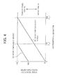
- Figure 4 shows a graphical representation of the algorithm as an example.
- the first reference value T 1 is set to 300.
- the second reference value T 2 is set to 120.
- the chromaticity-noise-removing-ratio parameter RC is such a variable that determines the replacement ratio on the basis of a linear ratio: specifically, when the chromaticity-noise-removing-ratio parameter RC equals 0, the chromaticity data BY xy , RY xy is replaced with the associated mean values at a rate of 1, that is, replaced completely, and when it equals 1, the chromaticity data BY xy , RY xy is replaced with the mean value at a rate of 0, that is, retained completely.
- the luminosity-noise-removing-ratio parameter RD is defined similarly so that luminosity noise removal is implemented on the basis of the same linear ratio as the chromaticity noise removal for the distribution parameter DP ranging from 0 to the second reference value T 2 (120): the luminosity-noise-removing-ratio parameter RD is set to 0.6 when the distribution parameter DP equals 0.
- the parameters RC, RD are computed by the chromaticity-noise-removing-rate computing section 10 and the luminosity-noise-removing-rate computing section 11 respectively.
- the mean chromaticity data BY av , RY av and the mean luminosity data YY av are calculated by the mean value computing section 13 according to the equations:
- the Y/C separator section 6 produces the following luminosity data YY xy from the BGR image data fed from the imaging section 1: 51 49 53 52 50 49 48 51 47 in a 3 ⁇ 3-pixel unit area in a monotonous part of an image; 10 30 70 15 50 90 20 80 85 in a 3 ⁇ 3-pixel unit area at an edge in the image; and 45 49 45 49 74 49 45 49 45 in a 3 ⁇ 3-pixel unit area in a monotonous part, of the image, which contains film particle noise.
- the chromaticity-noise-removing -rate computing section 10 computes a chromaticity-noise-removing-ratio parameter RC from the distribution parameter DP fed from the distribution parameter computing section 9 according to equation 3 for each unit area.
- the luminosity noise removing section 15 computes replacement luminosity data YY xy ' for the target pixel from the luminosity data YY xy fed from the Y/C separator section 6, the mean luminosity data YY av fed from the mean value computing section 13, and the luminosity-noise-removing-ratio parameter RD fed from the luminosity-noise-removing-rate computing section 11 according to equation 5 for each unit area, so as to replace the luminosity data YY xy of the target pixel with the replacement luminosity data YY xy '. All the pixels are subjected to this process until all the luminosity data YY xy is replaced with replacement luminosity data YY xy '
- the original luminosity data does not change in the process, and the resulting luminosity data is 51 49 53 52 50 49 48 51 47 Monotonous parts inherently do not much require effective blurring.
- the replacement ratio for the mean luminosity data YY av is 0, completely retaining the original luminosity data YY xy . Consequently, in the blurring process of the present invention, the non-edge parts of the image are blurred, i.e., the noise is removed, but the edges are not affected and the image retains its contrast.
- the resulting luminosity data is 45 49 45 49 70 49 45 49 45
- the distribution parameter DP(C) computed is 55.8, which shows that the luminosity data YY xy is now more uniform than before the transformation and that the noise peak has been attenuated. Noise has been successfully reduced.
- the actual distribution parameter DP(C) is therefore far smaller.
- FIG. 5 to Figure 10 show results of the foregoing image processing in accordance with present invention applied to the image data read by the imaging section 1.
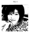
- Figure 5 shows, as mentioned earlier, an output of the image data that is read by the imaging section 1 and passed on to the exposure section 5 with no noise removing process implemented at all. The output is no different from the original image.
- Figure 6 shows an output of the imace data that is read by the imaging section 1 and subjected to chromaticity noise removal before being fed to the exposure section 5.
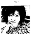
- Figure 7 shows an output of the image data that is read by the imaging section 1 and subjected to both chromaticity noise removal and luminosity noise removal before being fed to the exposure section 5.
- Figures 5-7 A comparison of Figures 5-7 shows that the facial skin and the fabric of clothes appear coarse in Figure 5 (original image), but less so in Figure 6 and even less so in Figure 7. Meanwhile, edge sharpness of the eyes, nose, body, etc. does not distinctly differ among Figures 5-7.
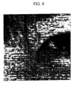
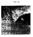
- Figures 8-10 show output results of the same image data as used for Figures 5-7, but enlarged and cropped near the inner end of the left eye, for better comparison at film particle levels.
- the output results confirm that the film particle noise, a cause for the coarse look in the image, is gradually removed from Figure 8 to Figure 9 and to Figure 10 and that edges appear little affected by the processing and are almost perfectly retained in Figures 6 and 7.
- the foregoing noise removal is implemented by a program stored on a recording medium that is readable by a computer.
- the recording medium may be a memory, for example, an ROM, required for the image processing section 4 in Figure 2 to execute the process or a program medium that is readable when inserted in an external reader device.
- the recorded program may be adapted so that it is accessible and executable by a microprocessor (not shown) or that it is preinstalled in the main device and ready for readout and loading into a program memory area (not shown) in the image processing section 4 where it is executed.
- the program medium may be adapted to be separable from the main device. It may be a nonvolatile medium: namely, a tape, such as a magnetic tape or a cassette tape; a magnetic disk, such as a floppy disk or a hard disk; an optical disk, such as a CD-ROM, an MO disk, an MD, or a DVD; a card, such as a memory or IC card or an optical card; or a semiconductor memory, such as a mask ROM, an EPROM, an EEPROM, or a flash ROM.
- a tape such as a magnetic tape or a cassette tape
- a magnetic disk such as a floppy disk or a hard disk
- an optical disk such as a CD-ROM, an MO disk, an MD, or a DVD
- a card such as a memory or IC card or an optical card
- semiconductor memory such as a mask ROM, an EPROM, an EEPROM, or a flash ROM.
- the system of the present invention is configured to connect to the Internet and other communications networks; the program medium may therefore by a volatile transmission medium to which the program is downloaded over a communications network when necessary.
- the program to be downloaded may be preinstalled in the main device or installed from a different recording medium when necessary.
- the content of the recording medium is not limited to a program and may include data.
- an image processing method in accordance with the present invention includes the steps of:
- Another image processing method in accordance with the present invention includes the features of this method and may be such that:
- those areas located close to edges are identified using the first reference value, since the image areas where the variation of the luminosity data is larger than the first reference value are located closer to edges than to monotonous parts in the image and the areas where the variation of the luminosity data is smaller than the first reference value are located closer to monotonous parts than to edges in the image.
- a priority is given to the smoothing of the chromaticity data which is relatively impervious to edge information attenuation, rather than to the smoothing of the luminosity data which is relatively susceptible to edge information attenuation, near monotonous parts.
- the rate of the luminosity noise removal can be rendered smaller if chromaticity noise is removed beforehand than if not.
- the smoothing of the luminosity data is selectively done when only it is effective. This produces better results in both the retainment of edges and the reduction of a coarse look of the image.
- a further image processing method in accordance with the present invention includes the features of the foregoing method and may be such that:
- a still further image processing method in accordance with the present invention includes the features of the foregoing method and may be such that:
- the specification of the first and second reference values enables the image to be divided into those areas close to monotonous parts, those areas close to edges, and the middle areas relatively far from both the monotonous parts and the edges, since those areas close to the monotonous parts are further divided into two groups according to whether the variation of the luminosity data is smaller than the second reference value or not.
- a further image processing method in accordance with the present invention includes the features of the foregoing method and may be such that
- Still another image processing method in accordance with the present invention includes the features of the foregoing method and may be such that the rate of the smoothing of the chromaticity data and the rate of the smoothing of the luminosity data are changed according to a distribution parameter of the luminosity data.
- the distribution parameter of the luminosity data is easily computable and still faithfully represents variations of the luminosity data: the distribution parameter is 0 if the luminosity data has no variation at all and takes an increasingly large positive value when the variation of the luminosity data increases starting from 0.
- the distribution parameter computed for the luminosity data enables easy discrimination, for example, among those areas close to monotonous parts, those areas close to edges, and the middle areas relatively far from both the monotonous parts and the edges.
- the balance can be easily optimized between the chromaticity noise removal and the luminosity noise removal.
- the distribution parameter is obtained by raising to the second power and then averaging the difference between the mean value of the luminosity data and the mean value of the luminosity data; the noise removal using the distribution parameter imparts a very natural look to the image, presumably, because the computation involves raising to the second power. Besides, the computation is simple and quick and makes great contributions to implement the image processing method by hardware.
- An image processing device in accordance with the present invention includes:
- Another image processing device in accordance with the present invention includes the features of the foregoing configuration and may be such that the smoothing rate computing section compares the variation of the luminosity data with a first reference value specified as to a degree of the variation of the luminosity data, and in image areas where the variation of the luminosity data is smaller than the first reference value, computes the rates given by such equations that the rate of the smoothing of the chromaticity data becomes larger than the rate of the smoothing of the luminosity data.
- the image processing device produces better results in both the retainment of edges and the reduction of a coarse look of the image.
- a further image processing device in accordance with the present invention includes the features of the foregoing configuration and may be such that the smoothing rate computing section compares the variation of the luminosity data with a second reference value specified as to a degree of the variation of the luminosity data so that the second reference value is smaller than the first reference value, and in image areas where the variation of the luminosity data is larger than the second reference value, computes the rates given by such equations that the luminosity data is not subjected to the smoothing.
- the image processing device produces better results in the retainment of edges and produces as good results in the reduction of a coarse look of the image.
- a still further image processing device in accordance with the present invention includes the features of the foregoing configuration and may be such that in image areas where the variation of the luminosity data is larger than the first reference value, the smoothing rate computing section computes the rates given by such equations that the luminosity data is not subjected to the smoothing and the chromaticity data is not subjected to the smoothing.
- Yet another image processing device in accordance with the present invention includes the features of the foregoing configuration and may be such that the smoothing rate computing section includes a reference specification section for assigning variable values to the reference values depending on an external input.
Landscapes
- Engineering & Computer Science (AREA)
- Multimedia (AREA)
- Signal Processing (AREA)
- Image Processing (AREA)
- Facsimile Image Signal Circuits (AREA)
- Color Image Communication Systems (AREA)
Applications Claiming Priority (2)
| Application Number | Priority Date | Filing Date | Title |
|---|---|---|---|
| JP2000227896 | 2000-07-27 | ||
| JP2000227896A JP3726653B2 (ja) | 2000-07-27 | 2000-07-27 | 画像処理方法、画像処理装置および画像処理方法を実行するプログラムを記録した記録媒体 |
Publications (3)
| Publication Number | Publication Date |
|---|---|
| EP1176801A2 true EP1176801A2 (de) | 2002-01-30 |
| EP1176801A3 EP1176801A3 (de) | 2005-06-01 |
| EP1176801B1 EP1176801B1 (de) | 2008-07-23 |
Family
ID=18721286
Family Applications (1)
| Application Number | Title | Priority Date | Filing Date |
|---|---|---|---|
| EP01117944A Expired - Lifetime EP1176801B1 (de) | 2000-07-27 | 2001-07-24 | Bildverarbeitungsvorrichtung, -verfahren, -programm und Speichermedium zum Speichern eines Bildverarbeitungsprogramms |
Country Status (5)
| Country | Link |
|---|---|
| US (2) | US6983069B2 (de) |
| EP (1) | EP1176801B1 (de) |
| JP (1) | JP3726653B2 (de) |
| CN (1) | CN1207895C (de) |
| DE (1) | DE60134917D1 (de) |
Cited By (5)
| Publication number | Priority date | Publication date | Assignee | Title |
|---|---|---|---|---|
| EP1811455A1 (de) * | 2006-01-23 | 2007-07-25 | Ricoh Company, Ltd. | Bildverarbeitungsvorrichtung, Abbildungsvorrichtung, Bildverarbeitungsverfahren und Computerprogrammprodukt |
| EP1885136A3 (de) * | 2006-07-31 | 2009-12-09 | Ricoh Company, Ltd. | Bildverarbeitungsvorrichtung, Abbildungsvorrichtung, Bildverarbeitungsverfahren und Computerprogrammprodukt |
| WO2010091971A1 (en) * | 2009-02-13 | 2010-08-19 | Oce-Technologies B.V. | Image processing system for processing a digital image and image processing method of processing a digital image |
| WO2010099048A3 (en) * | 2009-02-26 | 2010-10-21 | Marvell World Trade Ltd. | Method and apparatus for spatial noise adaptive filtering for digital image and video capture systems |
| EP1991008A4 (de) * | 2006-02-27 | 2012-04-18 | Nikon Corp | Bildverarbeitungseinrichtung zur korrektur des massiven gefühls eines bildes, bildverarbeitungsprogramm, bildverarbeitungsverfahren und elektronische kamera |
Families Citing this family (27)
| Publication number | Priority date | Publication date | Assignee | Title |
|---|---|---|---|---|
| JP3726653B2 (ja) * | 2000-07-27 | 2005-12-14 | ノーリツ鋼機株式会社 | 画像処理方法、画像処理装置および画像処理方法を実行するプログラムを記録した記録媒体 |
| ATE552120T1 (de) | 2001-12-24 | 2012-04-15 | L 1 Secure Credentialing Inc | Verdeckte variableninformationen auf id- dokumenten und verfahren zu ihrer herstellung |
| US7694887B2 (en) | 2001-12-24 | 2010-04-13 | L-1 Secure Credentialing, Inc. | Optically variable personalized indicia for identification documents |
| US7815124B2 (en) * | 2002-04-09 | 2010-10-19 | L-1 Secure Credentialing, Inc. | Image processing techniques for printing identification cards and documents |
| US7824029B2 (en) | 2002-05-10 | 2010-11-02 | L-1 Secure Credentialing, Inc. | Identification card printer-assembler for over the counter card issuing |
| US7804982B2 (en) | 2002-11-26 | 2010-09-28 | L-1 Secure Credentialing, Inc. | Systems and methods for managing and detecting fraud in image databases used with identification documents |
| CN100399792C (zh) * | 2002-12-05 | 2008-07-02 | 瑞昱半导体股份有限公司 | 一种去除边界影像拉链状模糊的方法与装置 |
| JP4066803B2 (ja) * | 2002-12-18 | 2008-03-26 | 株式会社ニコン | 画像処理装置、画像処理プログラム、画像処理方法および電子カメラ |
| JP4042563B2 (ja) * | 2002-12-27 | 2008-02-06 | セイコーエプソン株式会社 | 画像ノイズの低減 |
| DE602004030434D1 (de) | 2003-04-16 | 2011-01-20 | L 1 Secure Credentialing Inc | Dreidimensionale datenspeicherung |
| EP1641283B1 (de) * | 2003-06-12 | 2019-01-09 | Nikon Corporation | Bildverarbeitungsverfahren, bildverarbeitungsprogramm, bildprozessor |
| JP2005045404A (ja) * | 2003-07-24 | 2005-02-17 | Ricoh Co Ltd | 画像処理装置、画像処理方法およびプログラム |
| RU2268051C2 (ru) * | 2003-12-15 | 2006-01-20 | Закрытое акционерное общество "Фармацевтическое предприятие "Оболенское" | Лекарственная форма, обладающая бактериостатическим действием, и способ ее изготовления |
| JP2005275900A (ja) * | 2004-03-25 | 2005-10-06 | Noritsu Koki Co Ltd | 粒子状ノイズ抑制のための画像処理方法及びプログラム及びこの方法を実施する画像処理装置 |
| US20060152596A1 (en) * | 2005-01-11 | 2006-07-13 | Eastman Kodak Company | Noise cleaning sparsely populated color digital images |
| JP2006215676A (ja) * | 2005-02-02 | 2006-08-17 | Noritsu Koki Co Ltd | 写真画像処理方法及び写真画像処理装置 |
| JP4780374B2 (ja) | 2005-04-21 | 2011-09-28 | Nkワークス株式会社 | 粒状ノイズ抑制のための画像処理方法及びプログラム及びこの方法を実施する粒状抑制処理モジュール |
| JP4683994B2 (ja) * | 2005-04-28 | 2011-05-18 | オリンパス株式会社 | 画像処理装置、画像処理方法、電子カメラ、スキャナ |
| TWI265390B (en) * | 2005-05-25 | 2006-11-01 | Benq Corp | Method for adjusting exposure of a digital image |
| JP4395789B2 (ja) * | 2006-10-30 | 2010-01-13 | ソニー株式会社 | 画像処理装置、撮像装置、画像処理方法およびプログラム |
| US8125682B2 (en) | 2007-12-06 | 2012-02-28 | Seiko Epson Corporation | Image processing apparatus and method of controlling the same |
| JP4978460B2 (ja) * | 2007-12-25 | 2012-07-18 | 富士ゼロックス株式会社 | バーコード認識装置及びプログラム |
| JP5229235B2 (ja) * | 2007-12-25 | 2013-07-03 | 日本電気株式会社 | 画像処理装置、画像処理方法、画像伸張装置、画像圧縮装置、画像伝送システムおよび画像処理用プログラム |
| US20090175535A1 (en) * | 2008-01-09 | 2009-07-09 | Lockheed Martin Corporation | Improved processing of multi-color images for detection and classification |
| CN101742086B (zh) * | 2008-11-07 | 2013-05-15 | 联咏科技股份有限公司 | 影像噪声消除方法 |
| JP5062156B2 (ja) * | 2008-12-09 | 2012-10-31 | Nkワークス株式会社 | 写真画像処理方法、写真画像処理プログラム、及び写真画像処理装置 |
| JP6015279B2 (ja) * | 2012-09-20 | 2016-10-26 | アイシン精機株式会社 | ノイズ除去装置 |
Family Cites Families (14)
| Publication number | Priority date | Publication date | Assignee | Title |
|---|---|---|---|---|
| JPS5868374A (ja) * | 1981-10-19 | 1983-04-23 | Nec Corp | テレビジヨン映像信号特殊効果装置 |
| JPS60167574A (ja) | 1984-02-10 | 1985-08-30 | Toshiba Corp | 画像ノイズ除去装置 |
| JP2543857B2 (ja) * | 1986-08-25 | 1996-10-16 | キヤノン株式会社 | カラ―画像処理装置 |
| JPH04501625A (ja) * | 1989-08-28 | 1992-03-19 | イーストマン・コダック・カンパニー | 重なり平面近似に基づく輝度及び色光度のデジタルイメージノイズ減少 |
| JPH0495488A (ja) * | 1990-08-10 | 1992-03-27 | Toshiba Corp | 色エッジエンハンサ |
| US5418574A (en) * | 1992-10-12 | 1995-05-23 | Matsushita Electric Industrial Co., Ltd. | Video signal correction apparatus which detects leading and trailing edges to define boundaries between colors and corrects for bleeding |
| US5729360A (en) | 1994-01-14 | 1998-03-17 | Fuji Xerox Co., Ltd. | Color image processing method and system |
| JP2906974B2 (ja) * | 1994-01-14 | 1999-06-21 | 富士ゼロックス株式会社 | カラー画像処理方法および装置 |
| JP2906975B2 (ja) * | 1994-01-14 | 1999-06-21 | 富士ゼロックス株式会社 | カラー画像処理方法および装置 |
| US5909249A (en) * | 1995-12-15 | 1999-06-01 | General Instrument Corporation | Reduction of noise visibility in a digital video system |
| US6148115A (en) * | 1996-11-08 | 2000-11-14 | Sony Corporation | Image processing apparatus and image processing method |
| US6556311B1 (en) * | 1997-05-28 | 2003-04-29 | Hewlett-Packard Development Co., L.P. | Luminance-based color resolution enhancement |
| US6031581A (en) * | 1997-06-26 | 2000-02-29 | Xerox Corporation | System for removing color bleed in a television image adapted for digital printing |
| JP3726653B2 (ja) * | 2000-07-27 | 2005-12-14 | ノーリツ鋼機株式会社 | 画像処理方法、画像処理装置および画像処理方法を実行するプログラムを記録した記録媒体 |
-
2000
- 2000-07-27 JP JP2000227896A patent/JP3726653B2/ja not_active Expired - Lifetime
-
2001
- 2001-07-09 CN CNB011159979A patent/CN1207895C/zh not_active Expired - Fee Related
- 2001-07-24 DE DE60134917T patent/DE60134917D1/de not_active Expired - Lifetime
- 2001-07-24 EP EP01117944A patent/EP1176801B1/de not_active Expired - Lifetime
- 2001-07-27 US US09/915,532 patent/US6983069B2/en not_active Expired - Fee Related
-
2005
- 2005-08-23 US US11/208,764 patent/US7426298B2/en not_active Expired - Fee Related
Cited By (8)
| Publication number | Priority date | Publication date | Assignee | Title |
|---|---|---|---|---|
| EP1811455A1 (de) * | 2006-01-23 | 2007-07-25 | Ricoh Company, Ltd. | Bildverarbeitungsvorrichtung, Abbildungsvorrichtung, Bildverarbeitungsverfahren und Computerprogrammprodukt |
| US8014627B2 (en) | 2006-01-23 | 2011-09-06 | Ricoh Company | Image processing apparatus, imaging apparatus, image processing method, and computer program product |
| EP1991008A4 (de) * | 2006-02-27 | 2012-04-18 | Nikon Corp | Bildverarbeitungseinrichtung zur korrektur des massiven gefühls eines bildes, bildverarbeitungsprogramm, bildverarbeitungsverfahren und elektronische kamera |
| EP1885136A3 (de) * | 2006-07-31 | 2009-12-09 | Ricoh Company, Ltd. | Bildverarbeitungsvorrichtung, Abbildungsvorrichtung, Bildverarbeitungsverfahren und Computerprogrammprodukt |
| US8351731B2 (en) | 2006-07-31 | 2013-01-08 | Ricoh Company, Ltd. | Image processing apparatus, imaging apparatus, image processing method, and computer program product |
| WO2010091971A1 (en) * | 2009-02-13 | 2010-08-19 | Oce-Technologies B.V. | Image processing system for processing a digital image and image processing method of processing a digital image |
| WO2010099048A3 (en) * | 2009-02-26 | 2010-10-21 | Marvell World Trade Ltd. | Method and apparatus for spatial noise adaptive filtering for digital image and video capture systems |
| US8655058B2 (en) | 2009-02-26 | 2014-02-18 | Marvell World Trade Ltd. | Method and apparatus for spatial noise adaptive filtering for digital image and video capture systems |
Also Published As
| Publication number | Publication date |
|---|---|
| CN1207895C (zh) | 2005-06-22 |
| EP1176801B1 (de) | 2008-07-23 |
| US7426298B2 (en) | 2008-09-16 |
| US6983069B2 (en) | 2006-01-03 |
| EP1176801A3 (de) | 2005-06-01 |
| JP2002044473A (ja) | 2002-02-08 |
| JP3726653B2 (ja) | 2005-12-14 |
| CN1335579A (zh) | 2002-02-13 |
| US20020051569A1 (en) | 2002-05-02 |
| US20050280741A1 (en) | 2005-12-22 |
| DE60134917D1 (de) | 2008-09-04 |
Similar Documents
| Publication | Publication Date | Title |
|---|---|---|
| US7426298B2 (en) | Image processing method, image processing device, image processing program, and recording medium for recording image processing program | |
| US6373992B1 (en) | Method and apparatus for image processing | |
| JP4081219B2 (ja) | 画像処理方法及び画像処理装置 | |
| US6856707B2 (en) | Image processing method and apparatus | |
| US5818975A (en) | Method and apparatus for area selective exposure adjustment | |
| US6667815B1 (en) | Method and apparatus for processing images | |
| US5978519A (en) | Automatic image cropping | |
| US6055340A (en) | Method and apparatus for processing digital images to suppress their noise and enhancing their sharpness | |
| US5513016A (en) | Method and apparatus for processing image signal | |
| EP0813336A2 (de) | Bildverarbeitungsverfahren und -gerät | |
| US6924839B2 (en) | Image-processing method and recording medium in which such an image-processing method is recorded | |
| KR20040044556A (ko) | 화상 처리 방법, 장치 및 프로그램 | |
| EP0402162A2 (de) | Bildverarbeitung mit Rauschanreicherungsoperatoren für Moiré-Verringerung und/oder Zufallspunkterzeugung | |
| JP3913356B2 (ja) | 画像処理方法 | |
| DE69528324T2 (de) | Bildverarbeitungsvorrichtung mit Bildinhaltsdiskriminierung | |
| JP3998369B2 (ja) | 画像処理方法および画像処理装置 | |
| EP1376469A2 (de) | Methode und System zur Erzeugung eines Weichzeichnereffekts in einem digitalen oder digitalisierten Bild | |
| JP3581270B2 (ja) | 画像処理装置、画像処理方法および画像処理プログラムを記録した記録媒体 | |
| EP1443459A2 (de) | Bildverarbeitungsverfahren und Vorrichtung zur Korrektur photographischer Bilder | |
| JP2000278532A (ja) | 画像処理装置、画像処理方法および画像処理プログラムを記録した記録媒体 | |
| JP3729118B2 (ja) | 画像処理方法、画像処理装置、画像処理プログラム、これを記録したコンピュータ読み取り可能な記録媒体 | |
| JP4017312B2 (ja) | 画像処理方法、画像処理装置および記録媒体 | |
| JP2005063022A (ja) | ノイズ画素マップ作成方法とその方法を実施する装置とプログラム及び写真プリント装置 | |
| JPH0348980A (ja) | 輪郭強調処理方式 | |
| EP1330114A2 (de) | Verfahren und Vorrichtung zur Verbesserung der Bildschärfe |
Legal Events
| Date | Code | Title | Description |
|---|---|---|---|
| PUAI | Public reference made under article 153(3) epc to a published international application that has entered the european phase |
Free format text: ORIGINAL CODE: 0009012 |
|
| AK | Designated contracting states |
Kind code of ref document: A2 Designated state(s): AT BE CH CY DE DK ES FI FR GB GR IE IT LI LU MC NL PT SE TR |
|
| AX | Request for extension of the european patent |
Free format text: AL;LT;LV;MK;RO;SI |
|
| PUAL | Search report despatched |
Free format text: ORIGINAL CODE: 0009013 |
|
| AK | Designated contracting states |
Kind code of ref document: A3 Designated state(s): AT BE CH CY DE DK ES FI FR GB GR IE IT LI LU MC NL PT SE TR |
|
| AX | Request for extension of the european patent |
Extension state: AL LT LV MK RO SI |
|
| 17P | Request for examination filed |
Effective date: 20050606 |
|
| AKX | Designation fees paid |
Designated state(s): DE FR GB |
|
| GRAP | Despatch of communication of intention to grant a patent |
Free format text: ORIGINAL CODE: EPIDOSNIGR1 |
|
| GRAS | Grant fee paid |
Free format text: ORIGINAL CODE: EPIDOSNIGR3 |
|
| GRAA | (expected) grant |
Free format text: ORIGINAL CODE: 0009210 |
|
| AK | Designated contracting states |
Kind code of ref document: B1 Designated state(s): DE FR GB |
|
| REG | Reference to a national code |
Ref country code: GB Ref legal event code: FG4D |
|
| REF | Corresponds to: |
Ref document number: 60134917 Country of ref document: DE Date of ref document: 20080904 Kind code of ref document: P |
|
| PLBE | No opposition filed within time limit |
Free format text: ORIGINAL CODE: 0009261 |
|
| STAA | Information on the status of an ep patent application or granted ep patent |
Free format text: STATUS: NO OPPOSITION FILED WITHIN TIME LIMIT |
|
| GBPC | Gb: european patent ceased through non-payment of renewal fee |
Effective date: 20081023 |
|
| 26N | No opposition filed |
Effective date: 20090424 |
|
| REG | Reference to a national code |
Ref country code: FR Ref legal event code: ST Effective date: 20090529 |
|
| PG25 | Lapsed in a contracting state [announced via postgrant information from national office to epo] |
Ref country code: FR Free format text: LAPSE BECAUSE OF NON-PAYMENT OF DUE FEES Effective date: 20080731 |
|
| PG25 | Lapsed in a contracting state [announced via postgrant information from national office to epo] |
Ref country code: GB Free format text: LAPSE BECAUSE OF NON-PAYMENT OF DUE FEES Effective date: 20081023 |
|
| PGFP | Annual fee paid to national office [announced via postgrant information from national office to epo] |
Ref country code: DE Payment date: 20120123 Year of fee payment: 11 |
|
| PG25 | Lapsed in a contracting state [announced via postgrant information from national office to epo] |
Ref country code: DE Free format text: LAPSE BECAUSE OF NON-PAYMENT OF DUE FEES Effective date: 20130201 |
|
| REG | Reference to a national code |
Ref country code: DE Ref legal event code: R119 Ref document number: 60134917 Country of ref document: DE Effective date: 20130201 |