EP1191273A2 - Raccord d'un tuyau de branchement et méthode pour raccorder des tuyaux utilisant ce raccord - Google Patents
Raccord d'un tuyau de branchement et méthode pour raccorder des tuyaux utilisant ce raccord Download PDFInfo
- Publication number
- EP1191273A2 EP1191273A2 EP01122018A EP01122018A EP1191273A2 EP 1191273 A2 EP1191273 A2 EP 1191273A2 EP 01122018 A EP01122018 A EP 01122018A EP 01122018 A EP01122018 A EP 01122018A EP 1191273 A2 EP1191273 A2 EP 1191273A2
- Authority
- EP
- European Patent Office
- Prior art keywords
- pipe joint
- branch pipe
- pipes
- connecting pipes
- joint body
- Prior art date
- Legal status (The legal status is an assumption and is not a legal conclusion. Google has not performed a legal analysis and makes no representation as to the accuracy of the status listed.)
- Granted
Links
- 238000000034 method Methods 0.000 title claims description 18
- 238000004891 communication Methods 0.000 claims abstract description 44
- 230000000630 rising effect Effects 0.000 claims description 6
- 238000003466 welding Methods 0.000 claims description 5
- 239000003507 refrigerant Substances 0.000 description 16
- 238000004806 packaging method and process Methods 0.000 description 9
- RYGMFSIKBFXOCR-UHFFFAOYSA-N Copper Chemical compound [Cu] RYGMFSIKBFXOCR-UHFFFAOYSA-N 0.000 description 8
- 238000005520 cutting process Methods 0.000 description 7
- 239000012530 fluid Substances 0.000 description 5
- 238000012986 modification Methods 0.000 description 4
- 230000004048 modification Effects 0.000 description 4
- 238000004140 cleaning Methods 0.000 description 3
- 229910052802 copper Inorganic materials 0.000 description 3
- 239000010949 copper Substances 0.000 description 3
- 230000000694 effects Effects 0.000 description 3
- 238000009434 installation Methods 0.000 description 3
- 239000000463 material Substances 0.000 description 3
- 238000001816 cooling Methods 0.000 description 2
- 238000010438 heat treatment Methods 0.000 description 2
- 239000007787 solid Substances 0.000 description 2
- 238000007792 addition Methods 0.000 description 1
- 238000004378 air conditioning Methods 0.000 description 1
- 230000000903 blocking effect Effects 0.000 description 1
- 238000005219 brazing Methods 0.000 description 1
- 238000007796 conventional method Methods 0.000 description 1
- 238000007493 shaping process Methods 0.000 description 1
- 238000005476 soldering Methods 0.000 description 1
Images




Classifications
-
- F—MECHANICAL ENGINEERING; LIGHTING; HEATING; WEAPONS; BLASTING
- F24—HEATING; RANGES; VENTILATING
- F24F—AIR-CONDITIONING; AIR-HUMIDIFICATION; VENTILATION; USE OF AIR CURRENTS FOR SCREENING
- F24F13/00—Details common to, or for air-conditioning, air-humidification, ventilation or use of air currents for screening
-
- F—MECHANICAL ENGINEERING; LIGHTING; HEATING; WEAPONS; BLASTING
- F16—ENGINEERING ELEMENTS AND UNITS; GENERAL MEASURES FOR PRODUCING AND MAINTAINING EFFECTIVE FUNCTIONING OF MACHINES OR INSTALLATIONS; THERMAL INSULATION IN GENERAL
- F16L—PIPES; JOINTS OR FITTINGS FOR PIPES; SUPPORTS FOR PIPES, CABLES OR PROTECTIVE TUBING; MEANS FOR THERMAL INSULATION IN GENERAL
- F16L41/00—Branching pipes; Joining pipes to walls
- F16L41/02—Branch units, e.g. made in one piece, welded, riveted
- F16L41/03—Branch units, e.g. made in one piece, welded, riveted comprising junction pieces for four or more pipe members
-
- F—MECHANICAL ENGINEERING; LIGHTING; HEATING; WEAPONS; BLASTING
- F24—HEATING; RANGES; VENTILATING
- F24F—AIR-CONDITIONING; AIR-HUMIDIFICATION; VENTILATION; USE OF AIR CURRENTS FOR SCREENING
- F24F1/00—Room units for air-conditioning, e.g. separate or self-contained units or units receiving primary air from a central station
- F24F1/06—Separate outdoor units, e.g. outdoor unit to be linked to a separate room comprising a compressor and a heat exchanger
- F24F1/26—Refrigerant piping
- F24F1/32—Refrigerant piping for connecting the separate outdoor units to indoor units
-
- Y—GENERAL TAGGING OF NEW TECHNOLOGICAL DEVELOPMENTS; GENERAL TAGGING OF CROSS-SECTIONAL TECHNOLOGIES SPANNING OVER SEVERAL SECTIONS OF THE IPC; TECHNICAL SUBJECTS COVERED BY FORMER USPC CROSS-REFERENCE ART COLLECTIONS [XRACs] AND DIGESTS
- Y10—TECHNICAL SUBJECTS COVERED BY FORMER USPC
- Y10T—TECHNICAL SUBJECTS COVERED BY FORMER US CLASSIFICATION
- Y10T29/00—Metal working
- Y10T29/49—Method of mechanical manufacture
- Y10T29/49428—Gas and water specific plumbing component making
-
- Y—GENERAL TAGGING OF NEW TECHNOLOGICAL DEVELOPMENTS; GENERAL TAGGING OF CROSS-SECTIONAL TECHNOLOGIES SPANNING OVER SEVERAL SECTIONS OF THE IPC; TECHNICAL SUBJECTS COVERED BY FORMER USPC CROSS-REFERENCE ART COLLECTIONS [XRACs] AND DIGESTS
- Y10—TECHNICAL SUBJECTS COVERED BY FORMER USPC
- Y10T—TECHNICAL SUBJECTS COVERED BY FORMER US CLASSIFICATION
- Y10T29/00—Metal working
- Y10T29/53—Means to assemble or disassemble
- Y10T29/5367—Coupling to conduit
-
- Y—GENERAL TAGGING OF NEW TECHNOLOGICAL DEVELOPMENTS; GENERAL TAGGING OF CROSS-SECTIONAL TECHNOLOGIES SPANNING OVER SEVERAL SECTIONS OF THE IPC; TECHNICAL SUBJECTS COVERED BY FORMER USPC CROSS-REFERENCE ART COLLECTIONS [XRACs] AND DIGESTS
- Y10—TECHNICAL SUBJECTS COVERED BY FORMER USPC
- Y10T—TECHNICAL SUBJECTS COVERED BY FORMER US CLASSIFICATION
- Y10T29/00—Metal working
- Y10T29/53—Means to assemble or disassemble
- Y10T29/53987—Tube, sleeve or ferrule
Definitions
- the present invention relates to a branch pipe joint and a method of connecting pipes using the branch pipe joint, and more particularly to a branch pipe joint having a number of connecting pipes, each having a different inner diameter, and to a method of connecting pipes using the above branch pipe joint.
- the multi-unit type air conditioner carries out a refrigerating cycle and is schematically shown as 61 in FIG. 16.
- the air conditioner 61 is constituted by sequentially connecting a compressor 62, a four-way valve 63, an outdoor side heat exchanger 64, an outdoor side refrigerant controller 65, a branch pipe joint 66b, indoor side refrigerant controllers 67, a plurality of indoor side heat exchangers 68 (68a, 68b and 68c) and a branch pipe joint 66a.
- the branch pipe joint 66a is connected to the branch pipe joint 66b through the respective indoor side refrigerant controllers 67 and the indoor side heat exchangers 68 (68a, 68b and 68c).
- the branch pipe joint 66b has the same shape as that of the branch pipe joint 66a.
- the solid arrows indicate a flow direction of the refrigerant at the time of heating operation of the air conditioner, while the broken arrows indicate a flow direction of the refrigerant at the time of cooling operation.
- each of the branch pipe joints 66 (66a and 66b) comprises a branch pipe joint body 67 having a cylindrical closed shape; a plurality of connecting pipes 68 welded to the branch pipe joint body 67 in a longitudinal direction thereof so with a constant interval p1 therebetween; and a common connecting pipe 69 welded to one end surface of the branch pipe joint body 67.
- the plurality of the connecting pipes 68 are normally formed of copper tubes, and have the same shape. As shown in FIG. 19, each of the connecting pipes 68 has a pipe shape having multiple steps whose outer and inner diameters are gradually reduced in an axial direction.
- a first step portion 68a communicating with a welding root portion 68z has an inner diameter of 19.0mm
- a second step portion 68b communicating with the first step 68a has an inner diameter of 15.9mm
- a third step portion 68c communicating with the second step 68b has an inner diameter of 12.7mm
- a fourth step portion 68d communicating with the third step portion 68c has an inner diameter of 9.5mm, respectively.
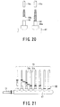
- the branch pipe joint 66 to which the plurality of connecting pipes 68 and the common connecting pipe 69 are welded, is prepared. Then, as shown in FIGs. 20 and 21, a position of each connecting pipe 68 having an inner diameter corresponding to an outer diameter of pipe 70 (70a, 70b) to be connected to the branch pipe joint 66 is selected, and the connecting pipe 68 is cut at that position by means of a pipe cutter. After an inner surface of the connecting pipe 68 is reshaped and finished, the pipe 70 is inserted into the connecting pipe and the connected portion is welded. In the case of the common connecting pipe 69, the same procedure is repeated, thereby to connect and weld a pipe 71 to the common connecting pipe 69.
- the connecting pipe 68 and the common connecting pipe 69 are cut at the installation site, so that copper powder is unavoidably generated and remains adhered to inner portions of the connecting pipe 68 and the common connecting pipe 69.
- the air conditioner 61 is assembled and operated with the copper powder being adhered, blocking and jamming are liable to result at the outdoor side refrigerant controller 65, the indoor side refrigerant controller 67 or the like, which can constitute a cause of failure of the air conditioner 61.
- connecting pipe 68 is cut by means of the pipe cutter, it is required to provide a large pitch p1 of about 160mm between the adjacent connecting pipes 68 so as to permit the pipe cutter to freely operate without any obstructions, so that the branch pipe joint 66 being formed must have a large size.
- the present invention has been achieved to solve the above described problems, and an object of the invention is to provide a branch pipe joint and a method of connecting pipes using the branch pipe joint which can be formed in a small size, and capable of being easily assembled into an air conditioner without requiring a cutting operation for the connecting pipes.
- a branch pipe joint comprising a branch pipe joint body having a hollow closed shape; a plurality of communication ports formed in the branch pipe joint body; a plurality of connecting pipes, each of which has one end portion fitted to the communication port while the other end portion is fitted to one of a plurality of pipes so that a fluid flows through the connecting pipes; and a common communication port provided to the branch pipe joint body through which the fluid flows; wherein the plurality of connecting pipes are composed of various pipes whose one end portions are fitted to the branch pipe joint body while the other end portions are fitted to the plurality of pipes through fitting portions, and sizes of the fitting portions are different from each other.
- the air conditioner can be easily assembled without requiring the cutting operation for the connecting pipes.
- the pipe cutter is not used for connecting pipes, the pitch between the adjacent connecting pipes can be reduced to be about 1/2 of that of conventional case, so that the branch pipe joint can be formed of a small size.
- the plurality of connecting pipes are selected from a group consisting of various pipes whose fitting portions are different from each other, and the various pipes and the branch pipe joint body are packed in the same package.
- said fitting portions are formed so as to have different inner diameters in accordance with the sizes of said connecting pipes. Further, it is also preferable that said fitting portions are formed so as to have different outer diameters in accordance with the sizes of said connecting pipes. Further, it is preferable that the outer diameters of end portions of the plurality of connecting pipes to be fitted to the plurality of communication ports are identical to each other. Further, it is also preferable that the inserting portions formed in the plurality of connecting pipes to be fitted to the plurality of communication ports have the same shape as each other.
- a method of connecting pipes comprising the steps of preparing a branch pipe joint body having a hollow shape and a plurality of communication ports; selecting connecting pipes to be fitted to a plurality of pipes that are to be connected to the branch pipe joint body from a group consisting of various connecting pipes having different inner diameters, the connecting pipes and the branch pipe joint body having been packed in one package; and connecting the pipes to the branch pipe joint body through the connecting pipes.
- the air conditioner can be easily assembled without requiring the cutting operation for the connecting pipes.
- the connecting pipes are selected from a group consisting of connecting pipes each having an identical outer diameter at one end portion thereof.
- a method of connecting pipes comprising the steps of preparing a branch pipe joint body having a hollow shape and a plurality of communication ports; selecting connecting pipes to be fitted to a plurality of pipes which are to be connected to the branch pipe joint body from a group consisting of at least one kind of connecting pipes having different inner diameters, the connecting pipes and the branch pipe joint body having been packed in one package; and connecting a part of the pipes to the branch pipe joint body through the connecting pipes while directly connecting the remaining pipes to the branch pipe joint body.
- FIG. 1 shows a multi-unit type air conditioner 1, a so called multi-air-conditioner, using a branch pipe joint of a first embodiment according to the present invention.
- the air conditioner 1 is constituted by sequentially connecting a compressor 2, a four-way valve 3, a yoked type branch pipe joint 20a, a plurality, for example two, sets of outdoor side heat exchangers 4 (4a, 4b), another yoked type branch pipe joint 20a, a multi-branched type branch pipe joint 10a, a plurality of indoor side heat exchangers 6 (6a, 6b - - and 6n) and a multi-branched type branch pipe joint 10b connected through pipes 5 (5a, 5b, - - and 5n).
- a plurality of electronic expansion valves 7i, 7o for controlling the flow of the refrigerant and solenoid valves 8i, 8o are provided in association with the indoor side heat exchangers 6 and the outdoor side heat exchangers 4.
- the reference numeral 9 (9a and 9b) denote pipes for communicating the indoor side heat exchangers 4 (4a and 4b) with the yoked type branch pipe joints 20a.
- the solid arrows indicate a flow direction of the refrigerant at the time of heating operation of the air conditioner, while the broken arrows indicate a flow direction of the refrigerant at the time of cooling operation.
- the branch pipe joint 10 (10a and 10b) comprises a branch pipe joint body 11 composed of copper and having a hollow cylindrically closed shape.
- This branch pipe joint body 11 comprises a plurality of projecting portions 12 and a plurality of communication ports 13 formed to the projecting portions 12.
- the projecting portions 12 comprise rising portions 15 formed at opening portions 14 provided in the branch pipe joint body 11, and a number of attaching pipe portions 16 welded to the rising portions 15. Each of the rising portions 15 is formed by burring the opening portion 14.
- the attaching pipe portion 16 has the inner diameter shown in FIG. 5, and an inner wall of the attaching pipe portion 16 constitutes the communication port 13.
- the projecting portions 12 are arranged so as to provide a predetermined pitch p as shown in FIG. 2. Therefore, the pipes 5 can be firmly connected to the branch pipe joint body 11 through connecting pipes 17 as described later without causing any leakage of the fluid (refrigerant).
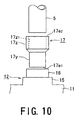
- the branch pipe joint 10 comprises connecting pipes 17 separately formed from the branch pipe joint body 11. As shown in FIGs. 4 and 6, one end portions 17e 1 of the connecting pipes 17 are fitted into the respective communication ports 13 having the same inner diameters as the outer diameters of the connecting pipes 17, while the other end portions of 17e 2 of the connecting pipes 17 are fitted around one pipe 5 among the pipes 5 (5a, 5b, -- and 5n) having various outer diameters.
- the fitting portion loosely fits into the communication port 13 formed in the projecting portion 12 of the branch pipe joint body 11.
- the fitting portion comprises an inserting portion 17y formed so as to have the same outer diameter as that of one end portion 17e 1 of the connecting pipe having an outer diameter of, for example, 15.9mm; and an outer fitting portion 17z communicating with the inserting portion 17y, the outer fitting portion having an outer diameter larger than that of inserting portion 17y and comprising an opening portion 17z 1 having an inner diameter capable of loosely fitting the pipe 5.
- the inner diameters of the outer fitting portions 17z are set to various sizes.
- the inner diameters consist of four kinds of diameters of 19.0mm, 15.9mm, 12.7mm and 9.5mm.
- all of the connecting pipes 17 are formed to provide the inserting portions having the same outer diameters, more preferably having the same outer diameter and the inner diameter, i.e., the same shapes. Due to the above arrangement, the number of kinds of the connecting pipes 17 can be reduced to a required minimum level.
- a common connecting pipe 18 having a common communication port 18a and having the same inner diameter as that of the attaching pipe portions 16 constituting the projecting portions 12.
- the common connecting pipe 18 can be directly formed to one end surface without providing the attaching pipe portion.
- the common connecting pipe may be formed so as to have an inner diameter larger than that of the attaching pipe portion.
- the inner diameters of the attaching pipe portions 16 are standardized to have the same value, more preferably to have the same shape, the outer diameters of one end portions of the connecting pipes fitting to the attaching pipe portions 16 can be the same. As a result, the number of kinds of the connecting pipes can be reduced.
- an outer diameter of one end portion of a communication pipe may be standardized to a predetermined size which is different from the outer diameter of one end portion of the connecting pipe. That is, when the outer diameters of one end portions of the communication pipes to be attached to one branch pipe joint body are standardized to be identical, the kinds of the connecting pipes can be reduced.
- the kinds of the connecting pipes are slightly increased, when several kinds of communication pipes, each having different outer diameters, are prepared and a connecting pipe having a larger diameter at one end portion thereof is applied to a large diametered pipe in accordance with the flow rate of the refrigerant flowing in the branch pipe joint, it becomes possible to make the flow of the refrigerant smooth.
- the projecting portion can be formed circularly, and with a sufficient strength and height from the branch pipe joint body, the projecting portion can be formed of only the rising portion without providing the attaching pipe portion.
- the projecting portion 12 is provided with the attaching pipe portion 16, the welding operation after the connecting pipes 17 are fitted to the branch pipe joint body 11 can be performed easily and securely.
- the inserting portion 17y is formed so as to have the same outer diameter as that of one end portion 17e 1 , the inserting portion need only have a shape capable of fitting with any of the communication ports 13 formed in the branch pipe joint body.
- a communication pipe 17A having a hollow truncated cone shape whose inserting portion 17 Ay is gradually enlarged from one end portion 17Ae 1 , thereof with a slight taper.
- a communication pipe 17B having a hollow square column shape whose inserting portion 17By extends from one end portion 17Be 1 thereof having a square shape so as to provide a constant cross sectional shape in an axial direction.
- a communication pipe 17C having a hollow square pyramid shape whose inserting portion 17Cy is gradually enlarged from one end portion 17Ce 1 thereof.
- the attaching pipe portion is also formed to have a shape so as to align with the shape of the inserting portion to be fitted to the attaching portion.
- a branch pipe joint body 11 together with a group of connecting pipes as the materials of the branch pipe joint 10 are packed in one packaging box.
- the group of the connecting pipes contains a number of the connecting pipes, for example, at least the number of the connecting pipes corresponds to a number of the communication ports 13 formed in the branch pipe joint body 11.
- the group of the connecting pipes consist of a plurality of kinds of connecting pipes 17, for example, four kinds of connecting pipes 17 each having a different inner diameter.
- the branch pipe joint body 11 is provided with eight communication ports 13 and the pipes to be connected consist of a pipe 5a having an outer diameter of 9.5mm; pipes 5b, 5c each having an outer diameter of 12.7mm; pipes 5d, 5e, 5f each having an outer diameter of 15.9mm; and pipes 5g, 5h each having an outer diameter of 19.0mm.
- the group of the connecting pipes consists of two connecting pipes 17a, each having an inner diameter of 9.5mm and an inserting portion 17y having the same outer diameter of 15.9mm; five pieces of connecting pipes 17b each having an inner diameter of 12.7mm; five pieces of connecting pipes 17c each having an inner diameter of 15.9mm; and two pieces of connecting pipes 17d each having an inner diameter of 19.0mm.
- the inner diameter of each of the connecting pipes has the same sizes as the outer diameter of each of pipes.
- the connecting pipes are formed to have inner diameters slightly lager than the outer diameters of the pipes so that each of the pipes can be inserted into the connecting pipe.
- the group of the connecting pipes consists of fourteen connecting pipes 17 in total, and the group of the connecting pipes 17, together with the branch pipe joint body 11, are packed in one packaging box B as shown in FIG. 15.
- the outer diameter of the pipe 5 is determined on the basis of the flow rate of refrigerant flowing in the outdoor side heat exchanger 4 and outdoor side heat exchanger 6.
- pipes having various outer diameters have been used for the air conditioners.
- the connecting pipes 17 may consist of less than four kinds of connecting pipes 17 having different inner diameters.
- the connecting pipes 17 are selected from the group consisting of a number of connecting pipes 17 having different inner diameters that are packed together with the branch pipe joint body 11 in the packaging box, the connecting pipes 17 having inner diameters corresponding to the outer diameters of the pipes 5 can be easily prepared.
- the pipes 5, the connecting pipes 17 and the branch pipe joint body 11 are firmly fixed by various methods such as welding W, brazing, soldering or the like. It is preferable that the non-selected connecting pipes 17 remaining in the packaging box B are reused.
- the connecting pipes 17 are selected from the group consisting of various connecting pipes so as to match to the outer diameters of the pipes 5 and then welded thereby to establish the communication in the air conditioner, unlike the conventional method, it is not necessary to select a position of the connecting pipe in accordance with an outer diameter of the pipe to be connected, and is not necessary to cut the connecting pipe at the position by means of a pipe cutter.
- the air conditioner can be easily assembled without requiring the cutting operation for the connecting pipes.
- the pipe cutter since the pipe cutter is not used for the connecting pipes, a space for operating the pipe cutter is not required. Accordingly, the pitch p between the adjacent connecting pipes 17 can be reduced to be about 80mm which is 1/2 of that of conventional case, so that the branch pipe joint 10 can have a small size.
- the branch pipe joint of the second embodiment is a yoked-type branch pipe joint 20 (20a, 20b).
- this yoked-type branch pipe joint 20 is formed of copper and has a hollow cylindrically closed shape, and comprises: a branch pipe joint body 21 formed by drawing work and shaping work; branched portions 21a, 21b provided to the branch pipe joint body 21 for constituting projecting portions through which a fluid flows in a branched manner; two pieces of connecting pipes 23a, 23b whose inserting portions (not shown) have the same outer diameter, one end of the connecting pipes being connected to the respective communication ports 22a, 22b while the other ends being connected to one of the plurality of pipes; and a common pipe connecting portion 24 formed in the branch pipe joint body 21 through which the fluid flows in a confluent state.
- the branch pipe joint body 21 is provided with two communication ports 22a, 22b of the branch pipe joint 20 and the pipes to be connected consist of a pipe 25a having an outer diameter of 19.0mm and a pipe 25b having an outer diameter of 50.8mm.
- the group of the connecting pipes consists of one connecting pipe having an inner diameter of 9.5mm, one connecting pipe having an inner diameter of 12.7mm; two connecting pipes each having an inner diameter of 15.9mm; two connecting pipes each having an inner diameter of 19.0mm; and one connecting pipe having an inner diameter of 50.8mm.
- the group of the connecting pipes consists of seven connecting pipes in total, and the group of the connecting pipes together with the branch pipe joint body 21 are packed in one packaging box.
- the pipes are connected by using the connecting pipes selected from the group consisting of various connecting pipes, thereby to prepare the branch pipe joint of the second embodiment.
- the branch pipe joint of this modified embodiment is constituted in such a manner that all of the pipes are not connected to the branch pipe joint body through the connecting pipes but a number of the pipes are directly communicated with the branch pipe joint body without using the connecting pipes.
- the branch pipe joint 30 of this modified embodiment since the outer diameters of a part of the pipes 31a, 31b among the pipes 31 have suitable sizes for fitting to the attaching pipe portions 32 having appropriate inner diameters, these pipes 31a, 31b can be directly connected to the attaching pipe portions 32 without using the connecting pipes.
- the attaching pipe portions 32 having typical inner diameters are provided to the branch pipe joint body 33 and then the pipes are directly communicated with the attaching pipe portions 32, the number of the connecting pipes to be used, as well as the number and kinds of the connecting pipes constituting the group can be effectively reduced.
- the branch pipe joint of this modified embodiment is constituted in such a manner that the two pipes are not connected to the branch pipe joint body through the connecting pipes but one pipe is directly communicated with the branch pipe joint body without using the connecting pipe.
- this pipe 41 a can be directly connected and fixed to the branching portion 42a without using the connecting pipe while only the pipe 41 b is connected and fixed to the branching portion 42b through the connecting pipe
- branching portions 42 having typical inner diameters t are provided to the branch pipe joint body 44, the chance that the pipes 41 are directly communicated with the branching portions 42 is increased, and the number and kinds of the connecting pipes to be used can be effectively reduced.
- both end portions of the connecting pipe 51 are formed with inserting portions 51y 1 , 51y 2 in an axial direction, and the inserting portions 51y 1 is fitted into the communication port 54 provided in the attaching pipe portion 53 of the branch pipe joint body 52 while the inserting portion 51y 2 is inserted in the pipe 55.
- the same effects as in the connecting pipe of the second embodiment can be expected.
- the connecting pipe 51 when the connecting pipe 51 is turned upside down, the connecting pipe 51 can be also used as a connecting pipe in the first and second embodiments. Further, when the connecting pipe in the first and second embodiments are inverted, the inverted connecting pipes can be also used as the connecting pipe 51 for this modified embodiment.
- both end portions of the connecting pipe to be used in the branch pipe joint according to the present invention may be inserted into the pipes or the attaching pipe portion.
- the connecting pipe can be also fitted over one of the pipe or the attaching portion, while fitted into the other member in an inserting manner.
- various fitting types such as fitting over-type and inserting-type or the like can be suitably adopted.
Landscapes
- Engineering & Computer Science (AREA)
- General Engineering & Computer Science (AREA)
- Mechanical Engineering (AREA)
- Chemical & Material Sciences (AREA)
- Combustion & Propulsion (AREA)
- Branch Pipes, Bends, And The Like (AREA)
- Air Filters, Heat-Exchange Apparatuses, And Housings Of Air-Conditioning Units (AREA)
Applications Claiming Priority (2)
| Application Number | Priority Date | Filing Date | Title |
|---|---|---|---|
| JP2000287604 | 2000-09-21 | ||
| JP2000287604A JP3745211B2 (ja) | 2000-09-21 | 2000-09-21 | 分岐ジョイント |
Publications (3)
| Publication Number | Publication Date |
|---|---|
| EP1191273A2 true EP1191273A2 (fr) | 2002-03-27 |
| EP1191273A3 EP1191273A3 (fr) | 2003-04-23 |
| EP1191273B1 EP1191273B1 (fr) | 2006-06-21 |
Family
ID=18771325
Family Applications (1)
| Application Number | Title | Priority Date | Filing Date |
|---|---|---|---|
| EP01122018A Expired - Lifetime EP1191273B1 (fr) | 2000-09-21 | 2001-09-13 | Raccord d'un tuyau de branchement et méthode pour raccorder des tuyaux utilisant ce raccord |
Country Status (6)
| Country | Link |
|---|---|
| US (1) | US6839966B2 (fr) |
| EP (1) | EP1191273B1 (fr) |
| JP (1) | JP3745211B2 (fr) |
| KR (1) | KR100388362B1 (fr) |
| CN (1) | CN1234991C (fr) |
| SG (1) | SG89420A1 (fr) |
Cited By (1)
| Publication number | Priority date | Publication date | Assignee | Title |
|---|---|---|---|---|
| EP3730874A4 (fr) * | 2018-01-22 | 2021-09-08 | Daikin Industries, Ltd. | Unité de ramification, dispositif de réfrigération et procédé d'installation de dispositif de réfrigération |
Families Citing this family (8)
| Publication number | Priority date | Publication date | Assignee | Title |
|---|---|---|---|---|
| CN102441770B (zh) * | 2011-10-08 | 2013-05-22 | 宁波市哈雷换热设备有限公司 | 一种具平面凸台的不锈钢集分水器主管的加工方法 |
| TWI588420B (zh) * | 2014-06-06 | 2017-06-21 | 台達電子工業股份有限公司 | 冷媒插座及具有該冷媒插座的空調設備 |
| CN106287986A (zh) * | 2016-09-29 | 2017-01-04 | 广东美的制冷设备有限公司 | 一种空调器及其控制方法 |
| JP6591682B2 (ja) * | 2017-04-27 | 2019-10-16 | 日立ジョンソンコントロールズ空調株式会社 | 冷媒流路切換ユニットおよび空気調和機 |
| KR200490863Y1 (ko) * | 2018-05-31 | 2020-01-14 | 주식회사 알만에이엠 | 천장용 환풍구 그릴 |
| US12135177B2 (en) * | 2020-08-14 | 2024-11-05 | Viking Vessel Holdings, Llc | Tube transition |
| US12130101B2 (en) * | 2020-08-14 | 2024-10-29 | Viking Vessel Holdings, Llc | Tube transition |
| KR102867611B1 (ko) * | 2021-12-03 | 2025-10-14 | 한국전자통신연구원 | 멀티 포트 가스 유량 제어 장치 |
Family Cites Families (29)
| Publication number | Priority date | Publication date | Assignee | Title |
|---|---|---|---|---|
| US913036A (en) * | 1908-11-14 | 1909-02-23 | Frederick W Pedersen | Sewer-pipe coupling and connection. |
| US1713640A (en) * | 1926-06-16 | 1929-05-21 | Frederick C Blanchard | Conduit structure |
| US1966403A (en) * | 1931-03-05 | 1934-07-10 | Nassau Products | Welding union |
| US2053443A (en) * | 1935-10-18 | 1936-09-08 | Superheater Co Ltd | Superheater element |
| US2217737A (en) * | 1938-04-20 | 1940-10-15 | Keystone Lubricating Company | Lubricating fitting |
| US2495615A (en) * | 1944-04-17 | 1950-01-24 | Round Root Corp | Welded coupling |
| US2441204A (en) * | 1944-05-17 | 1948-05-11 | Nusbaum Lee | Apparatus for filling containers |
| US2710443A (en) * | 1949-06-07 | 1955-06-14 | Babcock & Wilcox Co | Method of making a restricted orifice tube joint |
| US2762635A (en) * | 1951-02-15 | 1956-09-11 | Babcock & Wilcox Co | Tube and header connections |
| US3262497A (en) * | 1960-08-22 | 1966-07-26 | Bethlehem Steel Corp | Header-tube assembly and fitting therefor |
| US3282612A (en) * | 1965-11-29 | 1966-11-01 | Gilbert W Younger | Tube retainer |
| US3470893A (en) * | 1968-03-04 | 1969-10-07 | Illinois Tool Works | Fluid distribution unit |
| US4015321A (en) * | 1974-12-23 | 1977-04-05 | Witter Melvin L | Welded pipe fitting and method of making same |
| GB1500995A (en) * | 1975-04-14 | 1978-02-15 | Kojima N | Method of connecting pipes and pipe joints used therein |
| US4175779A (en) * | 1978-01-18 | 1979-11-27 | Foster Wheeler Energy Corporation | Stress control collar |
| US4321911A (en) * | 1979-08-15 | 1982-03-30 | Offutt Worthington W | Modular solar collector system |
| GB2072291B (en) * | 1980-03-12 | 1984-03-21 | Myson Group Ltd | Manifold |
| DE3012854A1 (de) * | 1980-04-02 | 1981-10-08 | Maile + Grammer Gmbh, 7407 Rottenburg | Rohrleitungsverteiler, insbesondere fuer warmwasserheuzungen |
| US4589688A (en) * | 1981-09-02 | 1986-05-20 | Fillpro Products, Inc. | Plumbing hookup kit |
| NO820529L (no) * | 1982-02-19 | 1989-09-12 | Thor Froelich Braathen | Kompresjonskopling. |
| DE3209950A1 (de) * | 1982-03-18 | 1983-09-22 | Joachim 4044 Kaarst Horn | Flanschverteiler fuer hydraulische anlagen mit hohen druecken |
| US4498693A (en) * | 1983-02-22 | 1985-02-12 | Schindele Ernst F | Rail system with passageways for the conduction of fluid flow |
| US4645242A (en) * | 1985-08-26 | 1987-02-24 | Dieterich Standard Corp. | High pressure mounting with positive lock |
| DE3928731A1 (de) * | 1989-08-30 | 1991-03-07 | Milutin Drljevic | Heizungs- bzw. kesselverteiler |
| US5400951A (en) * | 1993-08-31 | 1995-03-28 | Showa Aluminum Corporation | Method of brazing a joint portion of an intake manifold with preplaced brazing |
| US5620314A (en) * | 1995-02-21 | 1997-04-15 | Worton; David M. | Hand-operated liquid pump with removable parts |
| JPH09242964A (ja) * | 1996-03-12 | 1997-09-16 | Matsuyama Denki Kk | 配管用フリージョイントの組立方法 |
| JPH11241798A (ja) * | 1998-02-25 | 1999-09-07 | Sekisui Chem Co Ltd | 分岐管継手 |
| JP3959834B2 (ja) * | 1998-03-30 | 2007-08-15 | 株式会社デンソー | 積層型熱交換器 |
-
2000
- 2000-09-21 JP JP2000287604A patent/JP3745211B2/ja not_active Expired - Fee Related
-
2001
- 2001-02-06 KR KR10-2001-0005590A patent/KR100388362B1/ko not_active Expired - Fee Related
- 2001-09-11 SG SG200105532A patent/SG89420A1/en unknown
- 2001-09-13 EP EP01122018A patent/EP1191273B1/fr not_active Expired - Lifetime
- 2001-09-21 US US09/956,912 patent/US6839966B2/en not_active Expired - Lifetime
- 2001-09-21 CN CNB01140860XA patent/CN1234991C/zh not_active Expired - Fee Related
Non-Patent Citations (1)
| Title |
|---|
| None |
Cited By (1)
| Publication number | Priority date | Publication date | Assignee | Title |
|---|---|---|---|---|
| EP3730874A4 (fr) * | 2018-01-22 | 2021-09-08 | Daikin Industries, Ltd. | Unité de ramification, dispositif de réfrigération et procédé d'installation de dispositif de réfrigération |
Also Published As
| Publication number | Publication date |
|---|---|
| CN1344878A (zh) | 2002-04-17 |
| KR20020023083A (ko) | 2002-03-28 |
| US20020033600A1 (en) | 2002-03-21 |
| KR100388362B1 (ko) | 2003-06-25 |
| CN1234991C (zh) | 2006-01-04 |
| EP1191273B1 (fr) | 2006-06-21 |
| JP2002098286A (ja) | 2002-04-05 |
| US6839966B2 (en) | 2005-01-11 |
| EP1191273A3 (fr) | 2003-04-23 |
| JP3745211B2 (ja) | 2006-02-15 |
| SG89420A1 (en) | 2002-06-18 |
Similar Documents
| Publication | Publication Date | Title |
|---|---|---|
| EP1191273B1 (fr) | Raccord d'un tuyau de branchement et méthode pour raccorder des tuyaux utilisant ce raccord | |
| US9797532B2 (en) | Pipe joint, air conditioner, method for producing connecting pipe, connecting pipe, and connection method | |
| JP2008533415A (ja) | クリンプされた流路入口を有する並流熱交換器 | |
| WO2017109933A1 (fr) | Échangeur de chaleur, climatiseur équipé de celui-ci, et procédé de fabrication pour tuyaux aplatis à coude double | |
| JP6548729B2 (ja) | 熱交換器および空気調和装置 | |
| JP6223603B2 (ja) | 熱交換器および空気調和装置 | |
| CN218582371U (zh) | 一种切换阀 | |
| CN112334719B (zh) | 截止阀及其制造方法 | |
| JP2004279029A (ja) | 室内機 | |
| JP4758186B2 (ja) | 冷暖同時運転対応エンジン駆動式ヒートポンプ | |
| CN101663547A (zh) | 分支管装置 | |
| US7565730B2 (en) | Method of connecting a tubing component to a pipe of an air-conditioning system | |
| US20050279485A1 (en) | Stacking-type, multi-flow, heat exchangers and methods for manufacturing such heat exchangers | |
| JP7118258B2 (ja) | 空気調和装置 | |
| JP2007032921A (ja) | 分流器及びその製造方法 | |
| CN102203537A (zh) | 内部热交换器的连接装置 | |
| JP2008106933A (ja) | 分岐管及び及び分岐管を用いた空気調和装置 | |
| JP3005832U (ja) | 空調用分岐管 | |
| KR20050111276A (ko) | 멀티 에어컨의 접속관 및 그 배관연결방법 | |
| KR102013499B1 (ko) | 여과기를 에어컨 배관에 설치하는 방법 | |
| JP2882551B2 (ja) | 冷媒分流器とその製造方法 | |
| KR20120008906A (ko) | 공기조화기의 냉매 분배순환용 분기관 조립체 | |
| JP2001153402A (ja) | 冷凍サイクル装置 | |
| CN118103646A (zh) | 热交换器、空调装置、以及热交换器的制造方法 | |
| KR20040088188A (ko) | 공기조화기의 냉매배관 연결장치 |
Legal Events
| Date | Code | Title | Description |
|---|---|---|---|
| PUAI | Public reference made under article 153(3) epc to a published international application that has entered the european phase |
Free format text: ORIGINAL CODE: 0009012 |
|
| 17P | Request for examination filed |
Effective date: 20010913 |
|
| AK | Designated contracting states |
Kind code of ref document: A2 Designated state(s): AT BE CH CY DE DK ES FI FR GB GR IE IT LI LU MC NL PT SE TR |
|
| AX | Request for extension of the european patent |
Free format text: AL;LT;LV;MK;RO;SI |
|
| PUAL | Search report despatched |
Free format text: ORIGINAL CODE: 0009013 |
|
| AK | Designated contracting states |
Designated state(s): AT BE CH CY DE DK ES FI FR GB GR IE IT LI LU MC NL PT SE TR |
|
| AX | Request for extension of the european patent |
Extension state: AL LT LV MK RO SI |
|
| AKX | Designation fees paid |
Designated state(s): DE FR GB |
|
| 17Q | First examination report despatched |
Effective date: 20040302 |
|
| GRAP | Despatch of communication of intention to grant a patent |
Free format text: ORIGINAL CODE: EPIDOSNIGR1 |
|
| GRAJ | Information related to disapproval of communication of intention to grant by the applicant or resumption of examination proceedings by the epo deleted |
Free format text: ORIGINAL CODE: EPIDOSDIGR1 |
|
| GRAP | Despatch of communication of intention to grant a patent |
Free format text: ORIGINAL CODE: EPIDOSNIGR1 |
|
| GRAS | Grant fee paid |
Free format text: ORIGINAL CODE: EPIDOSNIGR3 |
|
| GRAA | (expected) grant |
Free format text: ORIGINAL CODE: 0009210 |
|
| AK | Designated contracting states |
Kind code of ref document: B1 Designated state(s): GB |
|
| REG | Reference to a national code |
Ref country code: GB Ref legal event code: FG4D |
|
| PLBE | No opposition filed within time limit |
Free format text: ORIGINAL CODE: 0009261 |
|
| STAA | Information on the status of an ep patent application or granted ep patent |
Free format text: STATUS: NO OPPOSITION FILED WITHIN TIME LIMIT |
|
| 26N | No opposition filed |
Effective date: 20070322 |
|
| PGFP | Annual fee paid to national office [announced via postgrant information from national office to epo] |
Ref country code: GB Payment date: 20190924 Year of fee payment: 19 |
|
| GBPC | Gb: european patent ceased through non-payment of renewal fee |
Effective date: 20200913 |
|
| PG25 | Lapsed in a contracting state [announced via postgrant information from national office to epo] |
Ref country code: GB Free format text: LAPSE BECAUSE OF NON-PAYMENT OF DUE FEES Effective date: 20200913 |