EP1193345B1 - Steuervorrichtung für eine Schienenschleifmaschine - Google Patents
Steuervorrichtung für eine Schienenschleifmaschine Download PDFInfo
- Publication number
- EP1193345B1 EP1193345B1 EP01402518A EP01402518A EP1193345B1 EP 1193345 B1 EP1193345 B1 EP 1193345B1 EP 01402518 A EP01402518 A EP 01402518A EP 01402518 A EP01402518 A EP 01402518A EP 1193345 B1 EP1193345 B1 EP 1193345B1
- Authority
- EP
- European Patent Office
- Prior art keywords
- grinding wheel
- control device
- accordance
- sensor
- detector
- Prior art date
- Legal status (The legal status is an assumption and is not a legal conclusion. Google has not performed a legal analysis and makes no representation as to the accuracy of the status listed.)
- Expired - Lifetime
Links
- XAGFODPZIPBFFR-UHFFFAOYSA-N aluminium Chemical compound [Al] XAGFODPZIPBFFR-UHFFFAOYSA-N 0.000 claims abstract description 4
- 229910052782 aluminium Inorganic materials 0.000 claims abstract description 4
- 230000005540 biological transmission Effects 0.000 claims description 4
- 238000001514 detection method Methods 0.000 claims description 4
- 239000000428 dust Substances 0.000 claims description 4
- 239000002245 particle Substances 0.000 claims description 4
- 239000008188 pellet Substances 0.000 claims description 4
- VVQNEPGJFQJSBK-UHFFFAOYSA-N Methyl methacrylate Chemical compound COC(=O)C(C)=C VVQNEPGJFQJSBK-UHFFFAOYSA-N 0.000 claims description 3
- 229920005372 Plexiglas® Polymers 0.000 claims description 3
- 244000045947 parasite Species 0.000 claims description 3
- 238000007664 blowing Methods 0.000 claims description 2
- 239000000835 fiber Substances 0.000 claims description 2
- 239000004411 aluminium Substances 0.000 claims 1
- 239000012780 transparent material Substances 0.000 claims 1
- 239000013307 optical fiber Substances 0.000 abstract description 6
- 238000000034 method Methods 0.000 description 4
- 238000003032 molecular docking Methods 0.000 description 2
- 238000013519 translation Methods 0.000 description 2
- 241000607479 Yersinia pestis Species 0.000 description 1
- 238000013459 approach Methods 0.000 description 1
- 230000015556 catabolic process Effects 0.000 description 1
- 238000006731 degradation reaction Methods 0.000 description 1
- 238000006073 displacement reaction Methods 0.000 description 1
- 230000010354 integration Effects 0.000 description 1
- 238000004519 manufacturing process Methods 0.000 description 1
- 230000003287 optical effect Effects 0.000 description 1
- 238000012545 processing Methods 0.000 description 1
- 230000001902 propagating effect Effects 0.000 description 1
- 238000012549 training Methods 0.000 description 1
Images

Classifications
-
- E—FIXED CONSTRUCTIONS
- E01—CONSTRUCTION OF ROADS, RAILWAYS, OR BRIDGES
- E01B—PERMANENT WAY; PERMANENT-WAY TOOLS; MACHINES FOR MAKING RAILWAYS OF ALL KINDS
- E01B31/00—Working rails, sleepers, baseplates, or the like, in or on the line; Machines, tools, or auxiliary devices specially designed therefor
- E01B31/02—Working rail or other metal track components on the spot
- E01B31/12—Removing metal from rails, rail joints, or baseplates, e.g. for deburring welds, reconditioning worn rails
- E01B31/17—Removing metal from rails, rail joints, or baseplates, e.g. for deburring welds, reconditioning worn rails by grinding
-
- B—PERFORMING OPERATIONS; TRANSPORTING
- B24—GRINDING; POLISHING
- B24B—MACHINES, DEVICES, OR PROCESSES FOR GRINDING OR POLISHING; DRESSING OR CONDITIONING OF ABRADING SURFACES; FEEDING OF GRINDING, POLISHING, OR LAPPING AGENTS
- B24B49/00—Measuring or gauging equipment for controlling the feed movement of the grinding tool or work; Arrangements of indicating or measuring equipment, e.g. for indicating the start of the grinding operation
- B24B49/12—Measuring or gauging equipment for controlling the feed movement of the grinding tool or work; Arrangements of indicating or measuring equipment, e.g. for indicating the start of the grinding operation involving optical means
Definitions
- the invention relates to a control system of the grinding wheel of a grinding machine parts such as rails, comprising a grinding device movable in a support frame between a position in which the grinding wheel is moved away from the grinding piece and a position in which the grinding wheel is in contact with this piece and a contact detection device grinding wheel with the piece.
- a control system of this type is known by the EP 05 93 361, in its application to the grinding of rails, to redraw the profile or to erase signs of wave wear or skating wheels.
- the main difficulty during such grinding comes from the rapid wear of the wheel during the job.
- Known methods use principles of pressure limitation of the wheel on the rail or manual approaches, which does not guarantee sufficient precision and does not allow integration into this automatic process.
- the present invention aims to propose a device capable of accurately detecting docking of the wheel on the rail and this whatever the conditions of use and the environment.
- control system is characterized in that the means of detecting the contact between the grinding wheel and the workpiece is a device for detecting sparks produced during of this contact.
- the detection device comprises a sensor of sparks arranged near the grinding wheel, connected to a detector of light, which is deported and arranged at a location protected against pests, and a means of transmission of light between the sensor and the detector.
- transmission means are formed by an optical fiber.
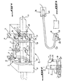
- the machine essentially comprises a grinding wheel 1 placed on a wheel trolley 2 movable along a beam 3 which is pivotally mounted to each of its ends on a moving device 4 in translation of the beam 3.
- This training device in translation 4 of the beam is mounted on a module 5 of rotation of the beam around the rail 6.
- This set is mounted on a support frame that has two elements 8, 9 each in the form of a frame through which extends the rail 6. The two frame elements are placed at a certain distance from each other, in the longitudinal direction of rail 6.
- the grinding wheel 1 is rotatably mounted on the carriage 2 and is rotated by a hydraulic motor 11.
- the device 4 for translational drive of the beam 3 essentially comprises a motor element 12 such as a cylinder provided with a rod 13 at the end of which is articulated the end of the beam 3.
- the machine of grinding further comprises a device for retaining the rail 6, which essentially comprises thrust members 15 as well as at each frame frame 8, 9 a rail clamping cylinder 17 and a clamping cylinder of rails 18, which act perpendicular to the direction of the rail to push it back onto the stop elements 19.
- the trolley-wheel 2 door above the wheel 1 a protection plate 20, advantageously aluminum, which extends perpendicular to the axis of the grinding wheel it.
- a sensor 22 which allows the recognition of the emission of sparks produced when the wheel 1 comes into contact with the piece to be grinded, in the example shown the rail 6.
- This sensor essentially comprises a block 21, advantageously made of aluminum, and a sensor member form of a plexiglass pellet 23, mounted in the block 21 at the bottom narrower of a conical channel 25 opening towards the grinding wheel 1 and arranged tangentially compared to the latter. The opening of the canal located at a distance from the contact point of the wheel with the rail.
- the pellet is housed in a support 28 being screwed in abutment on the end an optical fiber 29.
- the fiber is maintained in the block by a clamping screw 30
- a blowing device of air is integrated in the block and comprises ducts 31 which open in channel 25 and through which air tablet is blown into the canal to prevent the dust and grinding particles can enter in the canal and get to the plexiglass pellet at bottom of the canal.
- the other end of the optical fiber 29 is connected to a 33 formed light detector advantageously by a photodiode and mounted, together with its electronics, in a waterproof case 34 fixed on the grinding carriage 2, as seen on the Figure 2.
- the housing 34 is remote from the sensor of sparks 22 and located at a location where it is protected against thermal variations, vibrations, grinding particles and dust.
- the housing is cooled to prevent component degradation that it contains. As seen in Figure 2, the housing is at the top of the carriage 2, above the protection plate 20.
- the grinding wheel is slightly inclined at an angle inclination of 1 or 2 ° relative to the rails, on the back of its longitudinal displacement movement. So the front of grinding wheel is biting and we get a almost point contact of the grinding wheel with the rail. The location of production of sparks during the landing of the grinding wheel on the rail is therefore well defined.
- the invention has many advantages over compared to the state of the art.
- a process optical detection of the docking of the wheel on the by recognition of the emission of sparks in taking into account in particular the frequency of light Issued according to the temperature of the detached grains and heated by friction, the invention is not subject to noise propagating in the rail.
- the offset light detecting means and controls, point of light capture by optical fibers ensures perfect protection against variations thermal, vibration, dust and noise.
- the protection against light parasites is ensured by the use of an infrared wavelength and an angle of capture of the end of the optical fiber. Protection against electrical noise is obtained by the arrangement in a compact block of the detector and the electronic processing unit.
Landscapes
- Engineering & Computer Science (AREA)
- Mechanical Engineering (AREA)
- Architecture (AREA)
- Civil Engineering (AREA)
- Structural Engineering (AREA)
- Constituent Portions Of Griding Lathes, Driving, Sensing And Control (AREA)
- Machines For Laying And Maintaining Railways (AREA)
Claims (10)
- Vorrichtung zur Steuerung der Schleifscheibe (1) einer Schleifmaschine für Werkstücke, wie etwa Schienen, mit einer Vorrichtung (2) zum Tragen der Schleifscheibe (1), die in einem Traggestell (8, 9) zwischen einer Stellung, in welcher die Schleifscheibe (1) vom zu schleifenden Werkstück (6) beabstandet ist, und einer Stellung verstellbar ist, in welcher die Schleifscheibe (1) mit diesem Werkstück in Kontakt steht, und einer Vorrichtung (22) zum Erfassen des Kontakts der Schleifscheibe (1) mit dem Werkstück (6), die aus einer Vorrichtung zum Erfassen der bei diesem Kontakt erzeugten Funken gebildet ist, dadurch gekennzeichnet, dass die Erfassungsvorrichtung einen Funkendetektor (22) enthält, der nahe der Schleifscheibe (1) angeordnet ist und mit einem Lichtsensor (33) verbunden ist, der versetzt und an einer vor Störungen geschützten Stelle angeordnet ist, sowie einem Mittel (29) zum Übertragen des Lichts zwischen dem Detektor (22) und dem Sensor (33).
- Steuerungsvorrichtung nach Anspruch 1, dadurch gekennzeichnet, dass die Mittel (29) zum Übertragen der Lichtsignale aus einem Lichtwellenleiter gebildet sind.
- Steuerungsvorrichtung nach Anspruch 1 oder 2, dadurch gekennzeichnet, dass der Detektor (22) ein Erfassungsglied (23) enthält, das an einem Ende eines einen Kanal (25) begrenzenden Gliedes angeordnet ist, welcher Kanal sich in Richtung der Schleifscheibe (1) öffnet, und dass das Übertragungsmittel (29) mit dem Erfassungsglied (23) verbunden ist.
- Steuerungsvorrichtung nach Anspruch 3, dadurch gekennzeichnet, dass der Detektor (22) einen Block (21) vorzugsweise aus Aluminium enthält, in dem der vorgenannte Kanal (25) in Form eines konischen Kanals ausgebildet ist, an dessen Boden das Erfassungsglied (23) angeordnet ist.
- Steuerungsvorrichtung nach einem der Ansprüche 3 oder 4, dadurch gekennzeichnet, dass das Erfassungsglied (23) eine Tablette aus transparentem Material, vorzugsweise aus Plexiglas ist.
- Steuerungsvorrichtung nach einem der Ansprüche 3 bis 5, dadurch gekennzeichnet, dass die Achse des Kanals (25) einen Neigungswinkel (α) gegenüber der zu schleifenden Fläche des zu schiebenden Werkstücks (6) aufweist, wobei der Winkel so gewählt ist, dass er eine optimale Erfassung der Funken gewährleistet, und tangential zum Entstehungsort der Funken angeordnet ist.
- Steuerungsvorrichtung nach einem der Ansprüche 3 bis 6, dadurch gekennzeichnet, dass der Detektor (22) Mittel (31) zum Einblasen von Druckluft in den Detektorkanal (25) enthält, um das Eindringen von Staub und Schleifpartikel in den Kanal zu verhindern.
- Steuerungsvorrichtung nach einem der Ansprüche 1 bis 7, dadurch gekennzeichnet, dass die Sensorvorrichtung ein Lichterfassungsglied, wie etwa eine Photodiode (33), enthält.
- Steuerungsvorrichtung nach einem der Ansprüche 1 bis 8, dadurch gekennzeichnet, dass eine Schutzplatte (20) zwischen Schleifscheibe und Sensorvorrichtung (33) angeordnet ist.
- Steuerungsvorrichtung nach einem der Ansprüche 1 bis 9, dadurch gekennzeichnet, dass die Schleiffläche der Schleifscheibe (1) einen geringen Neigungswinkel (α) aufweist, der einen quasipunktförmigen Kontakt der Schleischeibe (1) mit dem zu schleifenden Werkstück (6) gewährleistet, wobei der Detektor (22) tangential zur quasipunktförmigen Kontaktstelle angeordnet ist.
Applications Claiming Priority (2)
| Application Number | Priority Date | Filing Date | Title |
|---|---|---|---|
| FR0012448 | 2000-09-29 | ||
| FR0012448A FR2814765B1 (fr) | 2000-09-29 | 2000-09-29 | Systeme de commande de la meule d'une machine de meulage notamment de rails |
Publications (2)
| Publication Number | Publication Date |
|---|---|
| EP1193345A1 EP1193345A1 (de) | 2002-04-03 |
| EP1193345B1 true EP1193345B1 (de) | 2005-04-20 |
Family
ID=8854833
Family Applications (1)
| Application Number | Title | Priority Date | Filing Date |
|---|---|---|---|
| EP01402518A Expired - Lifetime EP1193345B1 (de) | 2000-09-29 | 2001-09-28 | Steuervorrichtung für eine Schienenschleifmaschine |
Country Status (4)
| Country | Link |
|---|---|
| EP (1) | EP1193345B1 (de) |
| AT (1) | ATE293720T1 (de) |
| DE (1) | DE60110177T2 (de) |
| FR (1) | FR2814765B1 (de) |
Cited By (1)
| Publication number | Priority date | Publication date | Assignee | Title |
|---|---|---|---|---|
| CN101966690A (zh) * | 2010-07-27 | 2011-02-09 | 上海瑞纽机械装备制造有限公司 | 光感测自动磨削探位系统及方法 |
Families Citing this family (4)
| Publication number | Priority date | Publication date | Assignee | Title |
|---|---|---|---|---|
| ITVE20110025A1 (it) * | 2011-04-26 | 2012-10-27 | Fama S R L | Macchina molatrice tangenziale. |
| CN110587232B (zh) * | 2019-09-07 | 2020-11-17 | 东莞天盛电子制品有限公司 | 一种导轨灯槽自动化生产线工艺 |
| CN113696025A (zh) * | 2021-10-15 | 2021-11-26 | 北京星通浩宇科技发展有限公司 | 一种钢铝复合轨贫铬层自动清除设备 |
| CN116551545B (zh) * | 2023-05-10 | 2024-02-13 | 南京惠然测控技术有限公司 | 一种传感器部件加工可降尘抛光装置 |
Family Cites Families (3)
| Publication number | Priority date | Publication date | Assignee | Title |
|---|---|---|---|---|
| JPS63200967A (ja) * | 1987-02-13 | 1988-08-19 | Toshiba Corp | 研削砥石姿勢制御装置 |
| JP2946662B2 (ja) * | 1990-07-03 | 1999-09-06 | 大同特殊鋼株式会社 | 棒鋼のバリ取機 |
| FR2696762B1 (fr) | 1992-10-14 | 1994-12-30 | Geismar Anc Ets L | Procédé de meulage de la jonction bout-à-bout par soudage notamment de deux rails et machine de meulage pour la mise en Óoeuvre de ce procédé. |
-
2000
- 2000-09-29 FR FR0012448A patent/FR2814765B1/fr not_active Expired - Fee Related
-
2001
- 2001-09-28 AT AT01402518T patent/ATE293720T1/de active
- 2001-09-28 EP EP01402518A patent/EP1193345B1/de not_active Expired - Lifetime
- 2001-09-28 DE DE60110177T patent/DE60110177T2/de not_active Expired - Lifetime
Cited By (1)
| Publication number | Priority date | Publication date | Assignee | Title |
|---|---|---|---|---|
| CN101966690A (zh) * | 2010-07-27 | 2011-02-09 | 上海瑞纽机械装备制造有限公司 | 光感测自动磨削探位系统及方法 |
Also Published As
| Publication number | Publication date |
|---|---|
| EP1193345A1 (de) | 2002-04-03 |
| ATE293720T1 (de) | 2005-05-15 |
| DE60110177D1 (de) | 2005-05-25 |
| FR2814765A1 (fr) | 2002-04-05 |
| FR2814765B1 (fr) | 2004-02-13 |
| DE60110177T2 (de) | 2006-03-09 |
Similar Documents
| Publication | Publication Date | Title |
|---|---|---|
| EP0249803B1 (de) | Einrichtung zur Steuerung der Näherungsgeschwindigkeit an ein Werkstück | |
| EP0119883B1 (de) | Verfahren und Vorrichtung zum Ausrichten eines Laserstrahls mittels optischer Visiermittel, und Verfahren zur Verwendung der Vorrichtung zum Kontrollieren der Ausrichtung | |
| CH700111B1 (fr) | Machine d'usinage par laser. | |
| FR2463658A1 (fr) | Machine-outil munie d'un dispositif de coupage par fusion | |
| EP1751490B1 (de) | Konturenlesegerät mit kraftsensor | |
| EP1193345B1 (de) | Steuervorrichtung für eine Schienenschleifmaschine | |
| EP0221802B1 (de) | Sicherheitswerkzeughalter für Werkzeugmaschine | |
| FR2696968A1 (fr) | Main de robot pour l'usinage à trois dimensions de pièces. | |
| EP1677944B1 (de) | Vielseitige und modulare werkstückhaltevorrichtung | |
| FR2769976A1 (fr) | Systeme pour mesurer des rails, en particulier des rails de roulement pour des grues, des appareils de service de rayonnages, des blocs de roues de roulement | |
| FR2699445A1 (fr) | Procédé pour le contrôle sur une meuleuse de l'adéquation, à une monture de lunettes, d'un verre à meuler. | |
| EP0044245B1 (de) | Greiforgan mit optischen Sensoren und Vorrichtung mit Anwendung dieses Organs | |
| FR2552452A1 (fr) | Procede et dispositif d'exploitation d'un brise-balles pour balles de fibres textiles | |
| EP0697591B1 (de) | Vorrichtung zur Kontrolle der Oberfläche einer Walzwerkwalze | |
| WO2017001027A1 (fr) | Tete pour dispositif de soudage | |
| FR2573724A1 (fr) | Procede et dispositif opto-electronique permettant a une structure mobile de suivre les deplacements d'une autre structure. | |
| EP0394898B1 (de) | Drehgestell mit zwei einstellbaren Achsen, drehbar unter dem Wagenkasten eines Eisenbahnwagens montiert | |
| FR2619737A1 (fr) | Tete de decoupage par laser | |
| EP2176625B1 (de) | Sensor | |
| FR3140002A1 (fr) | Appareil et procédé de marquage laser à autofocus mécanique | |
| FR2682943A1 (fr) | Dispositif a chariot pour inspecter une paroi verticale ou inclinee. | |
| EP0336793B1 (de) | Vorrichtung zur Ortung eines Objektes durch Abtasten des Objektes mit einem Lichtstrahl | |
| EP0839605A1 (de) | Brillengestellhalter | |
| FR3135007A1 (fr) | Dispositif de maintien d’un quartier de bois | |
| EP1266999A1 (de) | Bewegliche Vorrichtung zur Bearbeitung von Schienen |
Legal Events
| Date | Code | Title | Description |
|---|---|---|---|
| PUAI | Public reference made under article 153(3) epc to a published international application that has entered the european phase |
Free format text: ORIGINAL CODE: 0009012 |
|
| AK | Designated contracting states |
Kind code of ref document: A1 Designated state(s): AT BE CH CY DE DK ES FI FR GB GR IE IT LI LU MC NL PT SE TR |
|
| AX | Request for extension of the european patent |
Free format text: AL;LT;LV;MK;RO;SI |
|
| 17P | Request for examination filed |
Effective date: 20020316 |
|
| AKX | Designation fees paid |
Free format text: AT BE CH CY DE DK ES FI FR GB GR IE IT LI LU MC NL PT SE TR |
|
| RTI1 | Title (correction) |
Free format text: CONTROL DEVICE FOR RAIL GRINDING MACHINE |
|
| GRAP | Despatch of communication of intention to grant a patent |
Free format text: ORIGINAL CODE: EPIDOSNIGR1 |
|
| GRAS | Grant fee paid |
Free format text: ORIGINAL CODE: EPIDOSNIGR3 |
|
| GRAA | (expected) grant |
Free format text: ORIGINAL CODE: 0009210 |
|
| AK | Designated contracting states |
Kind code of ref document: B1 Designated state(s): AT BE CH CY DE DK ES FI FR GB GR IE IT LI LU MC NL PT SE TR |
|
| PG25 | Lapsed in a contracting state [announced via postgrant information from national office to epo] |
Ref country code: FI Free format text: LAPSE BECAUSE OF FAILURE TO SUBMIT A TRANSLATION OF THE DESCRIPTION OR TO PAY THE FEE WITHIN THE PRESCRIBED TIME-LIMIT Effective date: 20050420 Ref country code: NL Free format text: LAPSE BECAUSE OF FAILURE TO SUBMIT A TRANSLATION OF THE DESCRIPTION OR TO PAY THE FEE WITHIN THE PRESCRIBED TIME-LIMIT Effective date: 20050420 Ref country code: IE Free format text: LAPSE BECAUSE OF FAILURE TO SUBMIT A TRANSLATION OF THE DESCRIPTION OR TO PAY THE FEE WITHIN THE PRESCRIBED TIME-LIMIT Effective date: 20050420 Ref country code: GB Free format text: LAPSE BECAUSE OF FAILURE TO SUBMIT A TRANSLATION OF THE DESCRIPTION OR TO PAY THE FEE WITHIN THE PRESCRIBED TIME-LIMIT Effective date: 20050420 Ref country code: TR Free format text: LAPSE BECAUSE OF FAILURE TO SUBMIT A TRANSLATION OF THE DESCRIPTION OR TO PAY THE FEE WITHIN THE PRESCRIBED TIME-LIMIT Effective date: 20050420 |
|
| REG | Reference to a national code |
Ref country code: GB Ref legal event code: FG4D |
|
| REG | Reference to a national code |
Ref country code: CH Ref legal event code: EP |
|
| REG | Reference to a national code |
Ref country code: GB Ref legal event code: ERR Free format text: THE ABOVE EP(UK) PATENT WAS ADVERTISED IN THE PATENTS AND DESIGNS JOURNAL NO. 6048 DATED 20050420 AS PUBLISHED IN ENGLISH NOTIFICATION HAS BEEN RECEIVED FROM THE EUROPEAN PATENT OFFICE THAT IT WAS PUBLISHED IN FRENCH |
|
| REG | Reference to a national code |
Ref country code: IE Ref legal event code: FG4D Free format text: LANGUAGE OF EP DOCUMENT: FRENCH |
|
| REF | Corresponds to: |
Ref document number: 60110177 Country of ref document: DE Date of ref document: 20050525 Kind code of ref document: P |
|
| PG25 | Lapsed in a contracting state [announced via postgrant information from national office to epo] |
Ref country code: GR Free format text: LAPSE BECAUSE OF FAILURE TO SUBMIT A TRANSLATION OF THE DESCRIPTION OR TO PAY THE FEE WITHIN THE PRESCRIBED TIME-LIMIT Effective date: 20050720 Ref country code: DK Free format text: LAPSE BECAUSE OF FAILURE TO SUBMIT A TRANSLATION OF THE DESCRIPTION OR TO PAY THE FEE WITHIN THE PRESCRIBED TIME-LIMIT Effective date: 20050720 |
|
| REG | Reference to a national code |
Ref country code: CH Ref legal event code: NV Representative=s name: TROESCH SCHEIDEGGER WERNER AG |
|
| PG25 | Lapsed in a contracting state [announced via postgrant information from national office to epo] |
Ref country code: ES Free format text: LAPSE BECAUSE OF FAILURE TO SUBMIT A TRANSLATION OF THE DESCRIPTION OR TO PAY THE FEE WITHIN THE PRESCRIBED TIME-LIMIT Effective date: 20050731 |
|
| REG | Reference to a national code |
Ref country code: SE Ref legal event code: TRGR |
|
| PG25 | Lapsed in a contracting state [announced via postgrant information from national office to epo] |
Ref country code: PT Free format text: LAPSE BECAUSE OF FAILURE TO SUBMIT A TRANSLATION OF THE DESCRIPTION OR TO PAY THE FEE WITHIN THE PRESCRIBED TIME-LIMIT Effective date: 20050920 |
|
| PG25 | Lapsed in a contracting state [announced via postgrant information from national office to epo] |
Ref country code: CY Free format text: LAPSE BECAUSE OF FAILURE TO SUBMIT A TRANSLATION OF THE DESCRIPTION OR TO PAY THE FEE WITHIN THE PRESCRIBED TIME-LIMIT Effective date: 20050928 |
|
| PG25 | Lapsed in a contracting state [announced via postgrant information from national office to epo] |
Ref country code: BE Free format text: LAPSE BECAUSE OF NON-PAYMENT OF DUE FEES Effective date: 20050930 Ref country code: LU Free format text: LAPSE BECAUSE OF NON-PAYMENT OF DUE FEES Effective date: 20050930 Ref country code: MC Free format text: LAPSE BECAUSE OF NON-PAYMENT OF DUE FEES Effective date: 20050930 |
|
| NLV1 | Nl: lapsed or annulled due to failure to fulfill the requirements of art. 29p and 29m of the patents act | ||
| GBV | Gb: ep patent (uk) treated as always having been void in accordance with gb section 77(7)/1977 [no translation filed] |
Effective date: 20050420 |
|
| REG | Reference to a national code |
Ref country code: IE Ref legal event code: FD4D |
|
| PLBE | No opposition filed within time limit |
Free format text: ORIGINAL CODE: 0009261 |
|
| STAA | Information on the status of an ep patent application or granted ep patent |
Free format text: STATUS: NO OPPOSITION FILED WITHIN TIME LIMIT |
|
| 26N | No opposition filed |
Effective date: 20060123 |
|
| BERE | Be: lapsed |
Owner name: SOC. DES ANCIENS ETABLISSEMENTS L. GEISMAR Effective date: 20050930 |
|
| PGFP | Annual fee paid to national office [announced via postgrant information from national office to epo] |
Ref country code: SE Payment date: 20121001 Year of fee payment: 12 Ref country code: IT Payment date: 20121001 Year of fee payment: 12 |
|
| REG | Reference to a national code |
Ref country code: SE Ref legal event code: EUG |
|
| PG25 | Lapsed in a contracting state [announced via postgrant information from national office to epo] |
Ref country code: SE Free format text: LAPSE BECAUSE OF NON-PAYMENT OF DUE FEES Effective date: 20130929 |
|
| PG25 | Lapsed in a contracting state [announced via postgrant information from national office to epo] |
Ref country code: IT Free format text: LAPSE BECAUSE OF NON-PAYMENT OF DUE FEES Effective date: 20130928 |
|
| REG | Reference to a national code |
Ref country code: FR Ref legal event code: PLFP Year of fee payment: 15 |
|
| PGFP | Annual fee paid to national office [announced via postgrant information from national office to epo] |
Ref country code: CH Payment date: 20150925 Year of fee payment: 15 |
|
| PGFP | Annual fee paid to national office [announced via postgrant information from national office to epo] |
Ref country code: AT Payment date: 20150925 Year of fee payment: 15 |
|
| PGFP | Annual fee paid to national office [announced via postgrant information from national office to epo] |
Ref country code: DE Payment date: 20151130 Year of fee payment: 15 |
|
| PGFP | Annual fee paid to national office [announced via postgrant information from national office to epo] |
Ref country code: FR Payment date: 20150925 Year of fee payment: 15 |
|
| REG | Reference to a national code |
Ref country code: DE Ref legal event code: R119 Ref document number: 60110177 Country of ref document: DE |
|
| REG | Reference to a national code |
Ref country code: CH Ref legal event code: PL |
|
| REG | Reference to a national code |
Ref country code: AT Ref legal event code: MM01 Ref document number: 293720 Country of ref document: AT Kind code of ref document: T Effective date: 20160928 |
|
| REG | Reference to a national code |
Ref country code: FR Ref legal event code: ST Effective date: 20170531 |
|
| PG25 | Lapsed in a contracting state [announced via postgrant information from national office to epo] |
Ref country code: CH Free format text: LAPSE BECAUSE OF NON-PAYMENT OF DUE FEES Effective date: 20160930 Ref country code: DE Free format text: LAPSE BECAUSE OF NON-PAYMENT OF DUE FEES Effective date: 20170401 Ref country code: LI Free format text: LAPSE BECAUSE OF NON-PAYMENT OF DUE FEES Effective date: 20160930 Ref country code: FR Free format text: LAPSE BECAUSE OF NON-PAYMENT OF DUE FEES Effective date: 20160930 |
|
| PG25 | Lapsed in a contracting state [announced via postgrant information from national office to epo] |
Ref country code: AT Free format text: LAPSE BECAUSE OF NON-PAYMENT OF DUE FEES Effective date: 20160928 |