EP1205301A2 - Verfahren zum Ausstossen von Flüssigkeit, Bilderzeugungsverfahren, Bilderzeugungsapparat und Flüssigkeitsausstosskopf - Google Patents
Verfahren zum Ausstossen von Flüssigkeit, Bilderzeugungsverfahren, Bilderzeugungsapparat und Flüssigkeitsausstosskopf Download PDFInfo
- Publication number
- EP1205301A2 EP1205301A2 EP01309460A EP01309460A EP1205301A2 EP 1205301 A2 EP1205301 A2 EP 1205301A2 EP 01309460 A EP01309460 A EP 01309460A EP 01309460 A EP01309460 A EP 01309460A EP 1205301 A2 EP1205301 A2 EP 1205301A2
- Authority
- EP
- European Patent Office
- Prior art keywords
- liquid
- droplets
- droplet
- discharging
- satellite
- Prior art date
- Legal status (The legal status is an assumption and is not a legal conclusion. Google has not performed a legal analysis and makes no representation as to the accuracy of the status listed.)
- Withdrawn
Links
- 239000007788 liquid Substances 0.000 title claims abstract description 196
- 238000007599 discharging Methods 0.000 title claims abstract description 68
- 238000000034 method Methods 0.000 title claims abstract description 50
- 230000009471 action Effects 0.000 claims abstract description 9
- 239000000976 ink Substances 0.000 claims description 94
- 238000006073 displacement reaction Methods 0.000 claims description 13
- 238000009835 boiling Methods 0.000 claims description 6
- 230000001629 suppression Effects 0.000 claims 2
- 230000008034 disappearance Effects 0.000 claims 1
- 238000011144 upstream manufacturing Methods 0.000 description 21
- 230000000740 bleeding effect Effects 0.000 description 13
- 238000010438 heat treatment Methods 0.000 description 13
- 230000005499 meniscus Effects 0.000 description 9
- 230000008602 contraction Effects 0.000 description 6
- 239000003595 mist Substances 0.000 description 6
- 238000012986 modification Methods 0.000 description 4
- 230000004048 modification Effects 0.000 description 4
- 239000000758 substrate Substances 0.000 description 4
- 238000010586 diagram Methods 0.000 description 3
- 230000008569 process Effects 0.000 description 3
- 238000013459 approach Methods 0.000 description 2
- 238000005469 granulation Methods 0.000 description 2
- 230000003179 granulation Effects 0.000 description 2
- 230000007246 mechanism Effects 0.000 description 2
- 238000010420 art technique Methods 0.000 description 1
- 230000015572 biosynthetic process Effects 0.000 description 1
- 238000004891 communication Methods 0.000 description 1
- 230000007423 decrease Effects 0.000 description 1
- 230000001934 delay Effects 0.000 description 1
- 238000011161 development Methods 0.000 description 1
- 230000000694 effects Effects 0.000 description 1
- 230000005684 electric field Effects 0.000 description 1
- 238000005868 electrolysis reaction Methods 0.000 description 1
- 230000001747 exhibiting effect Effects 0.000 description 1
- 230000006870 function Effects 0.000 description 1
- 230000006872 improvement Effects 0.000 description 1
- 230000008447 perception Effects 0.000 description 1
- 230000004044 response Effects 0.000 description 1
- 238000005549 size reduction Methods 0.000 description 1
- 238000001228 spectrum Methods 0.000 description 1
- 230000007480 spreading Effects 0.000 description 1
Images


Classifications
-
- B—PERFORMING OPERATIONS; TRANSPORTING
- B41—PRINTING; LINING MACHINES; TYPEWRITERS; STAMPS
- B41J—TYPEWRITERS; SELECTIVE PRINTING MECHANISMS, i.e. MECHANISMS PRINTING OTHERWISE THAN FROM A FORME; CORRECTION OF TYPOGRAPHICAL ERRORS
- B41J2/00—Typewriters or selective printing mechanisms characterised by the printing or marking process for which they are designed
- B41J2/005—Typewriters or selective printing mechanisms characterised by the printing or marking process for which they are designed characterised by bringing liquid or particles selectively into contact with a printing material
- B41J2/01—Ink jet
- B41J2/21—Ink jet for multi-colour printing
- B41J2/2121—Ink jet for multi-colour printing characterised by dot size, e.g. combinations of printed dots of different diameter
- B41J2/2128—Ink jet for multi-colour printing characterised by dot size, e.g. combinations of printed dots of different diameter by means of energy modulation
-
- B—PERFORMING OPERATIONS; TRANSPORTING
- B41—PRINTING; LINING MACHINES; TYPEWRITERS; STAMPS
- B41J—TYPEWRITERS; SELECTIVE PRINTING MECHANISMS, i.e. MECHANISMS PRINTING OTHERWISE THAN FROM A FORME; CORRECTION OF TYPOGRAPHICAL ERRORS
- B41J2/00—Typewriters or selective printing mechanisms characterised by the printing or marking process for which they are designed
- B41J2/005—Typewriters or selective printing mechanisms characterised by the printing or marking process for which they are designed characterised by bringing liquid or particles selectively into contact with a printing material
- B41J2/01—Ink jet
- B41J2/135—Nozzles
- B41J2/14—Structure thereof only for on-demand ink jet heads
- B41J2/14016—Structure of bubble jet print heads
- B41J2/14032—Structure of the pressure chamber
- B41J2/14048—Movable member in the chamber
-
- B—PERFORMING OPERATIONS; TRANSPORTING
- B41—PRINTING; LINING MACHINES; TYPEWRITERS; STAMPS
- B41J—TYPEWRITERS; SELECTIVE PRINTING MECHANISMS, i.e. MECHANISMS PRINTING OTHERWISE THAN FROM A FORME; CORRECTION OF TYPOGRAPHICAL ERRORS
- B41J2/00—Typewriters or selective printing mechanisms characterised by the printing or marking process for which they are designed
- B41J2/005—Typewriters or selective printing mechanisms characterised by the printing or marking process for which they are designed characterised by bringing liquid or particles selectively into contact with a printing material
- B41J2/01—Ink jet
- B41J2/21—Ink jet for multi-colour printing
- B41J2/2107—Ink jet for multi-colour printing characterised by the ink properties
-
- B—PERFORMING OPERATIONS; TRANSPORTING
- B41—PRINTING; LINING MACHINES; TYPEWRITERS; STAMPS
- B41J—TYPEWRITERS; SELECTIVE PRINTING MECHANISMS, i.e. MECHANISMS PRINTING OTHERWISE THAN FROM A FORME; CORRECTION OF TYPOGRAPHICAL ERRORS
- B41J2202/00—Embodiments of or processes related to ink-jet or thermal heads
- B41J2202/01—Embodiments of or processes related to ink-jet heads
- B41J2202/06—Heads merging droplets coming from the same nozzle
Definitions
- the present invention relates to on-demand type method and apparatus for discharging liquid, and particularly, to a method and an apparatus or a head for discharging liquid which are capable of using satellite droplet groups in the same manner as a main droplet in an appropriately discharged state, and which achieve a high-speed and high-frequency discharge.
- the present invention further relates to a liquid discharging method, an image forming apparatus, a liquid discharge apparatus, and a liquid discharge head which can be used for the entire spectrum of the technical field including printers which uses various liquids by bringing them into minute droplets.
- Figs. 2A to 2C illustrate states of droplet discharging resulting from the occurrence of this speed distribution.
- a main droplet is discharged at a speed V1', and a group of smaller satellite droplets are gradually brought into minute droplets, so that the speed thereof become V2, V3, V4, V5, and V6 in descending order (V1' > V2 > V3 > V4 > V5 > V6).
- V1' > V2 > V3 > V4 > V5 > V6 V1' > V2 > V3 > V4 > V5 > V6.
- a droplet having a speed from V4 onward comes into mist constituted of minute droplets, as described later.
- Japanese Laid-Open Patent Applications Nos. 9-1790 and 10-193649 which are applied based on a concept of using the above-described satellite droplets for image forming, in a state individually separated, with respect to the main droplet, disclose the technique which makes variable the dot area to be formed by bringing the satellite droplets close to the main droplet by controlling a drive pulse to an electromechanical transducer for bubble forming. Also, Japanese Laid-Open Patent Applications No.
- mist Minute droplets, which is named mist, and each of which is more minute than a droplet, such as satellite droplet, having a velocity component and a quantity enough to adhere to a paper surface tend to increase in the number as the main droplet decreases in the quantity.
- Japanese Examined Patent Application Publication No. 5-57913, and the corresponding U.S. Patent No. 468539, which recognize this mist issue, discloses that the problem of the occurrence of a plurality of satellite droplets with respect to a main droplet can be solved by a method wherein all satellite droplets are coalesced with the main droplet by performing first, second, and third pulse drives for a piezoelectric element.
- the Japanese Examined Patent Application Publication No. 5-57913 does not analyze the mechanism that the satellite drops are coalesced with the main droplet is not analyzed, but discloses a technical concept of allowing the satellite droplets to be coalesced with the main droplet in a space.
- U.S. Patent No. 4491851 the condition for preventing the occurrence of satellite droplets by performing first and second pulse drives for a piezoelectric element as in the case of the above patents, and the condition that, even if the satellite droplets are generated, satellite droplets are coalesced with a main drop as being in a high-speed satellite-dot area condition, are disclosed in Fig. 9 relative to the conventional satellite-droplet generation area condition.
- 2000-227081 which proposes means for coalescing a satellite droplet with a main droplet by a discharging method using an electrothermal transducer which forms a bubble, discloses a method wherein a satellite droplet is coalesced with a main droplet by increasing the speed of the satellite droplet by a movable member displaced by one-time bubble forming.
- the technical level of the conventional arts recognized from the foregoing is such that plural-time displacements for discharging satellite droplets are performed with respect to a piezoelectric element.
- the mainstream of the conventional arts is the technique of integrating occurred satellite droplets into a main drop in response to the driving conditions for providing the above-described plural-time deformations to the piezoelectric element.
- the plural-time deformations for discharge with respect to the piezoelectric element runs counter to the increasing of the driving frequency, and delays the return of the meniscus after discharging to the steady state. Therefore, this counteracts the improvement in the print speed by a high-speed and high-frequency drive.
- the conventional arts are only at a technical level at which satellite droplets are used so as to eventually enlarge the shot image of a main droplet when viewing the image, since the image is formed with satellite droplets coalesced with or brought close to the main droplet.
- the present invention in a first aspect, provides a liquid discharging method for a liquid discharge head which includes a discharge port constituting the portion for discharging liquid, an energy generating element generating the energy for discharging liquid, and liquid flow paths communicating with the discharge port and having the energy generating element, and which discharges liquid from the discharge port by the energy of the energy generating element.
- This liquid discharging method comprises the step of projecting a liquid column from the discharge port; the step of discharging the liquid column after a main droplet has separated, and separating the liquid column into a plurality of satellite droplets; and the step of coalescing the plurality of satellite droplets.
- the present invention provides an image forming method for a liquid discharge head which includes a discharge port constituting the portion for discharging liquid; an energy generating element generating the energy for discharging liquid; and liquid flow paths communicating with the discharge port and having the energy generating element, which forms a plurality of droplets by discharging the liquid from the discharge port by the energy of the energy generating element, and which forms an image by forming a plurality of dots by shooting the plurality of droplets onto a recording medium.
- the plurality of dots is formed of a main droplet which flies at the start; and a droplet formed by making capture and coalesce a plurality of satellite droplets discharged as a result of the discharge action of the main droplet, before the satellite droplets have been shot onto the recording medium.
- the present invention provides an image forming method for a liquid discharge head which includes a discharge port constituting the portion for discharging liquid; an energy generating element generating the energy for discharging liquid; and liquid flow paths communicating with the discharge port and having the energy generating element, which forms a plurality of droplets by discharging the liquid from the discharge port by the energy of the energy generating element, and which forms an image by forming a plurality of dots by shooting the plurality of droplets onto a recording medium.
- an image is formed by using a pair of reactive inks constituted of a black ink and a color ink as the liquid, and by superimposing a plurality of dots of the color ink on each dot of the black ink, the dots of the color ink being smaller than the dots of the black ink.
- the present invention provides a liquid discharge apparatus, comprising a liquid discharge head which includes a discharge port constituting the portion for discharging liquid, an energy generating element generating the energy for discharging liquid, and liquid flow paths communicating with the discharge port and having the energy generating element, which forms a plurality of droplets by discharging the liquid from the discharge port by the energy of the energy generating element, and which performs recording by shooting the plurality of droplets onto a recording medium, and a carriage for conveying the liquid discharge head relative to the recording medium.
- the liquid discharge head forms the plurality of droplets using a main droplet which flies at the start, and a droplet formed by making capture and coalesce a plurality of satellite droplets discharged as a result of the discharge action of the main droplet, before the satellite droplets have been shot onto the recording medium; and the liquid discharge head shoots the plurality of droplets onto the recording medium with a space interposed therebetween.
- the present invention provides a liquid discharge head which includes a discharge port constituting the portion for discharging liquid; an energy generating element generating the energy for discharging liquid, and liquid flow paths communicating with the discharge port and having the energy generating element, which forms a plurality of droplets by discharging the liquid from the discharge port by the energy of the energy generating element, and which performs recording by shooting the plurality of droplets onto a recording medium.
- the plurality of dots is formed of a main droplet which flies at the start; and a droplet formed by making capture and coalesce a plurality of satellite droplets discharged as a result of the discharge action of the main droplet, before the satellite droplets have been shot onto the recording medium.
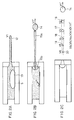
- FIGs. 1A to 1G are sectional views of a liquid discharge head in accordance with a first embodiment of the present invention, the sectional views being taken along the liquid flow path direction, wherein processes of liquid discharging are illustrated in sequence;
- Figs. 2A to 2C are sectional views of a conventional liquid discharge head taken along the liquid flow path direction;
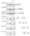
- Figs. 3A to 3G are sectional views of a liquid discharge head in accordance with a second embodiment of the present invention, the sectional views being taken along the liquid flow path direction, wherein processes of liquid discharging are illustrated in sequence;
- Figs. 4A to 4H are sectional views of a liquid discharge head in accordance with a third embodiment of the present invention, the sectional views being taken along the liquid flow path direction;
- Figs. 5A to 5H are sectional views of a liquid discharge head in accordance with a fourth embodiment of the present invention, the sectional views being taken along the liquid flow path direction;
- Fig. 6 is a diagram showing the relationship among a carriage carrying a head, paper as a recording medium, and discharged droplets;
- Fig. 7 is a diagram showing two dots shot onto paper by the liquid discharge head in accordance with the fourth embodiment of the present invention.
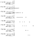
- Figs. 8A to 8E are views showing a black ink underlaid with color inks in a conventional example and embodiments of the present invention.
- Figs. 9A to 9E are views showing modifications of the embodiment in accordance with the present invention shown in Figs. 8A to 8E;
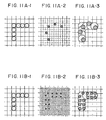
- Figs. 10A to 10C are schematic views showing appearances wherein a black ink is underlaid with cyan, magenta, and yellow inks which react with the black ink;
- Fig. 11A and 11B are recording states when the resolution of color inks are higher than those of the black inks in accordance with a conventional example and the embodiment of the present invention.
- Figs. 1A to 1G are sectional views taken along the liquid flow path direction of a liquid discharge head in accordance with a first embodiment of the present invention, wherein characteristic phenomena in liquid flow paths are illustrated separately in processes from Figs. 1A to 1G.
- a heating unit 5 is provided on a smooth element substrate 1, and liquid flow paths 30 are disposed on the smooth element substrate 1 so as to face the heating unit 5.
- the liquid flow paths 30 communicates with a discharge port 7, as well as communicates with a common liquid chamber for supplying liquid to a plurality of liquid flow paths 30 on the opposite side of the discharge port 7, and receive from this common liquid chamber the liquid commensurating in the quantity with the liquid discharged from the discharge port 7.
- the meniscus of the liquid charged into the liquid flow paths 30 is formed so that the capillary force occurring at the discharge port 7 and along the inner walls of the liquid flow paths 30 communicating with the discharge port 7, commensurates with the inner pressure (generally exhibiting a negative pressure) of the common liquid chamber, in the vicinity of the discharge port 7.
- the liquid flow paths 30 are formed by jointing the element substrate 1 having the heating unit 5 to a top plate 2. In the area in the vicinity of the interface where the heating unit 5 and the liquid to be discharged are in contact, there exists a bubble generating area which makes the liquid to be discharged generate a bubble when the heating unit 5 is rapidly heated.
- a movable member 4 is disposed in the liquid flow paths 30 having this bubble generating area so that at least one portion thereof faces the heating unit 5.
- the movable member 4 is a kind of one-end supported cantilever shape which has a free end on the downstream side toward the discharge port 7, and which is supported by supporting member disposed on further toward the upstream side than the liquid flow paths 30.
- the free end is positioned in the vicinity of the center of the bubble generating area, or of the heating unit 5 in order to suppress the growth of a half of the bubble on the upstream side, the half of the bubble influences back wave toward the upstream side and the inertia of the liquid.
- the movable member 4 can be displaced relative to the supporting member in accordance with the growth of the bubble occurring in the bubble generating area.
- the fulcrum when the movable member is displaced is the end portion of the supporting portion of the movable member 4 in the supporting member.
- a stopper (controlling portion) 3 is positioned at the upper portion of the center of the bubble generating area, and controls the displacement of the movable member 4 so as to be within a given range in order to suppress the growth of a half of the bubble on the upstream side.
- a low flow-path resistance area which has a flow-path resistance lower than that of the liquid flow paths 30, is provided on the upstream side with respect to the stopper 3.
- the flow path structure in the low flow-path resistance area is arranged so as to reduce the flow path resistance to the liquid movement, by eliminating an upper wall therefrom and by enlarging the cross area of the flow paths.
- a head structure which is characterized in that the liquid flow toward the upstream side of liquid flow paths and the bubble growth toward the upstream side thereof are inhibited by the displaced movable member 4.
- the discharging operation of the liquid discharge head in accordance with this embodiment will be described in detail.
- Figs. 1A to 1G the appearances are illustrated wherein a main droplet and a droplet formed by coalescing a group of satellite drops are shot onto a recording medium by a one-time discharge action.
- Fig. 6 the variations of the volume of the bubble 6 and the displacement quantity of the movable member 4 in this time are illustrated.
- Fig. 1A shows the state wherein an energy such as electrical energy is applied to the heating unit 5, and wherein a bubble is thereby expanding.
- an energy such as electrical energy
- a portion of the liquid filling the bubble generating area is heated by the heating unit 5
- a bubble 6 occurs as a result of a film boiling, and the bubble grows and the volume thereof increases with time.
- the displacement of the movable member 4 starts later than the variation of the bubble 6 in the volume due to the rebound force of the movable member 4.
- the movement of the liquid toward the upstream side, i.e., toward the common liquid chamber occurs, and this movement grows into a large flow because of the presence of the low flow-path resistance area.
- the movable member 4 is displaced until it approaches or contacts the stopper 3, further displacement thereof is restricted, so that the liquid movement is also significantly suppressed there. More specifically, in the state wherein the movable member 4 is displaced, the resistance to the flow toward the upstream side of the liquid flow paths 30 (at least further toward the upstream side than the center of the bubble generating area) increases, thereby largely suppressing the communication of the liquid and bubble between the liquid flow paths 30 and the common liquid chamber situated at the upstream side thereof.
- the growth of the bubble 6 toward the upstream side is also inhibited by the movable member 4.
- the movable member 4 since the moving force of the liquid toward the upstream side is large, the movable member 4 is kept in a deflected state under a large stress which pulls the movable member 4 toward the upstream side, and during which the bubble 6 grows up to the maximum volume thereof as described above.
- the liquid within the liquid flow paths 30 moves toward the downstream side and upstream side, due to the pressure on the basis of the generation of the bubble 6.
- the movable member 4 On the upstream side, the movable member 4 is displaced by the growth of the bubble 6, while on the downstream side, discharged liquid 8 is ejected from the discharge port 7 in a column shape. This is because the discharge port 7 is small, and the discharge power is sufficiently large.
- the tip of the ink column 8 is flying at a speed V1.
- the portion between the part on the discharge port side of the bubble 6 and the discharge port is in a state wherein a straight flow-path structure with respect to the liquid flow is kept, so to speak, a "linear communicating state". It is more preferable to create an ideal state wherein discharging conditions such as the discharge direction and/or discharge speed of a discharged liquid are stabilized at an extremely high level, by making linearly agree the propagation direction of the pressure wave generated at bubble generation, the flow direction of the liquid accompanied therewith, and the discharge direction.
- this embodiment is configured so that the heating unit 5, particularly the discharge port 7 side of the heating unit 5 (i.e., the downstream side thereof), which has an influence particularly on the discharge port 7 side of the bubble 6, is directly connected to the discharge port 7 in a straight line.
- This configuration is in a state wherein, if there is no liquid within the liquid flow paths 30, the heating unit 5, particularly the downstream side thereof can be observed from the outside of the discharge port 7.
- the flow resistance on the upstream side in the liquid flow paths 30 is increased by the contact between the displaced movable member 4 and the stopper, and the contraction energy of the bubble 6 acts as a force moving the liquid in the vicinity of the discharge port toward the upstream side.
- the meniscus is pulled from the discharge port 7 into the liquid flow paths 30, thereby pulling in the liquid column toward the discharge port side with a strong power.
- a constricted portion occurs in the vicinity of the tip of the discharged droplet, and the discharged droplet tapers away toward the root thereof.
- the tip of the ink column 8 flies at a speed V1' in the form of an independent drop, i.e., the main droplet 9.
- the tip 8a of the ink column flies at a speed V2, but V2 becomes smaller than V1', since the ink column is subjected to the force of the pull-in component (see Fig. 1C).
- Due to the downward displacement of the movable member 4 as a result of the contraction of the bubble the ink on the ink supply system side start to be supplied at a dash.
- a velocity component in the discharge direction is given to the rear end 8c of the ink column 8 by a high-speed refill.
- the rear end 8c therefore, has a speed larger than V2, and the portion 8b wherein the speed of the ink column 8 is the smallest, assumes a constricted shape.
- the movable member 4 is displaced upward by a rebound, and blocks the liquid flow paths, thereby reducing a refill quantity, so that the overall flow of the ink is slowed down, and that the ink column 8 and the meniscus 11 are divided from each other.
- the ink column 8 are divided into two, i.e., a front-end satellite droplet 10a and a rear-end satellite droplet 10b.
- the speed V3' of the rear-end satellite droplet 10b at this time is represented by V1'> V3'> V2.
- the rear-end satellite droplet 10b runs after the front-end satellite droplet 10a and approaches it.
- Fig. 1F once the two satellite droplets 10a and 10b have become close to each other, they are subjected to the influence of a slip stream, and the approaching speed thereof becomes larger.
- the satellite droplets 10a is captured by and coalesced with the satellite droplets 10b into one droplet. The result is that, as a whole, two droplets, i.e., a main droplet and the one satellite droplet are shot onto a recording medium.
- FIGs. 3A to 3G shows a discharge head in accordance with a second embodiment of the present invention, wherein a piezoelectric element 40 is used in place of the electrothermal transducer.
- a piezoelectric element 40 is used in place of the electrothermal transducer.
- FIGs. 4A to 4H discharge heads in accordance with third and fourth embodiments of the present invention are shown, respectively.
- the third and fourth embodiments are each modifications of the first embodiment, and their dimensions are identical with each other.
- Figs. 4A to 4H, and Figs. 5A to 5H discharge heads in accordance with third and fourth embodiments of the present invention are shown, respectively.
- the third and fourth embodiments are each modifications of the first embodiment, and their dimensions are identical with each other.
- a drive was performed by a single pulse (pulse width: 1.5 ⁇ s), while in Fig. 5 (fourth embodiment), a drive was performed by double pulses (a preliminary pulse width: 0.4 ⁇ s, an interval time: 2.3 ⁇ s, and a main pulse width: 1.2 ⁇ s).
- the overall discharge quantity is 5 ng for the discharge head configuration in Fig. 4 (third embodiment), and 6 ng for the discharge head configuration in Fig. 5 (fourth embodiment).
- a plurality of satellite droplets is coalesced after capturing, two stable dots constituted of a main droplet and a satellite droplet can be formed.
- Fig. 5H shows the state immediately before the two satellite droplets has coalesced into one droplet.
- Fig. 6 is a diagram showing the relationship among a carriage carrying a head, paper as a recording medium, and discharged droplets.
- FIG. 7 illustrates dots on paper in the case of the configuration in Fig. 5 (fourth embodiment).
- two dots have substantially equal diameters, and the distance D between the two dots is 55 ⁇ m, the diameter R1 of each of the droplets is 18 ⁇ m, and the diameter R2 of each of the dots on the paper (bleeding rate: 2.0) is 36 ⁇ m. It can be seen from the figure that the two dots have been shot on the paper in good conditions.
- an overlay-type ink is used as a black ink
- a penetration-type ink is used as a color ink in order to make the black character quality and the color image quality compatible with each other.
- a reactive ink is used for preventing the bleeding between a black ink and a color ink, and that the bleeding can be prevented by recording a reactive color image under a black image or at the portion adjacent thereto.
- the discharge rates of the black ink and the color ink are also important. However, when the discharge rates of the two inks are equal, it is important that they react with each other over a wide range of area on paper.
- Figs. 8A to 8E illustrate the underlaid state of color inks by a conventional art and the underlaid state of color inks by a novel technique in accordance with an embodiment of the present invention.
- Figs. 8A to 8D show the forming positions of black dots, cyan dots, magenta dots, and yellow dots, respectively.
- Fig. 8E shows the dot forming positions on paper with respect to the image recording positions in data.
- appearances wherein dots are formed while spreading on the real paper are schematically illustrated. As shown in Figs.
- the novel technique in accordance with this embodiment allows two recording dots to be recorded by a one-time discharge the conventional art technique, so that each of the recording dots of cyan, magenta, and yellow cover a larger area on the paper.
- these reactive inks can effectively react on the surface of the recording medium, thereby efficiently suppressing the bleeding between the black ink and the color ink.
- two recording dots are formed by a one-time discharge.
- supposing the discharge volume at a one-time discharge is identical, it will be efficient in preventing bleeding to disperse a dot into a plurality of dots and to distribute an ink widely and shallowly on paper as shown in Figs. 9A to 9E.
- This embodiment is arranged to form two dots by a one-time drive in consideration of elongating the lifetime of the heater.
- it will be possible to distribute an ink widely and shallowly as in the above-described case, by recording dots with a small discharge volume in a predetermined recording area by performing plural-time discharges. This enables the bleeding between the black ink and the color ink to be efficiently suppressed.
- Figs. 11A-1 to 11A-3 show that a second ink (color ink) has a recording resolution twice as high longitudinally and laterally as those of a first ink (black ink).
- Figs. 11B-1 to 11B-3 show that the second ink has a recording resolution four times as high longitudinally and laterally as those of the first ink.
- the discharge volume of the second ink is smaller than that of the first ink, and droplets of the second ink with a small quantity are arranged to be recorded under a plurality of droplets of the first ink.
- Each of the ink droplets in Figs. 11A-1 to 11A-3 has a volume four times as large as that in Figs. 11B-1 to 11B-3, but the ink droplet in Figs. 11B-1 to 11B-3 covers wider range than that in Figs. 11A-1 to 11A-3, and thereby can inhibit more efficiently the bleeding between the black ink and the color ink.
- Figs. 10A to 10C schematically illustrate the appearances wherein the black ink is underlaid with the cyan, magenta, and yellow inks which react with the black ink. These arrangements prevent bleeding and provides a superior recording density balance.
- Fig. 10A even when the recording dots of the cyan, magenta, and yellow inks exist within the recording dot of the black ink, or as shown in Fig. 10B, even when the recording dots of these color inks exist within the black ink or adjacently thereto, bleeding can be efficiently suppressed.
- Fig. 10C even when the cyan, magenta, and yellow inks form recording dots different in size from one another, a similar effect can be obtained.
- the main droplet and the satellite droplets are separated by a small discharge bore and a large power, and further a plurality of satellite droplets is coalesced after capturing, it is possible to form two stable dots without mist.
Landscapes
- Particle Formation And Scattering Control In Inkjet Printers (AREA)
- Ink Jet (AREA)
Applications Claiming Priority (2)
| Application Number | Priority Date | Filing Date | Title |
|---|---|---|---|
| JP2000343749A JP2002144570A (ja) | 2000-11-10 | 2000-11-10 | 液滴吐出方法、画像形成方法、液体吐出装置およびヘッド |
| JP2000343749 | 2000-11-10 |
Publications (2)
| Publication Number | Publication Date |
|---|---|
| EP1205301A2 true EP1205301A2 (de) | 2002-05-15 |
| EP1205301A3 EP1205301A3 (de) | 2004-01-02 |
Family
ID=18818068
Family Applications (1)
| Application Number | Title | Priority Date | Filing Date |
|---|---|---|---|
| EP01309460A Withdrawn EP1205301A3 (de) | 2000-11-10 | 2001-11-08 | Verfahren zum Ausstossen von Flüssigkeit, Bilderzeugungsverfahren, Bilderzeugungsapparat und Flüssigkeitsausstosskopf |
Country Status (3)
| Country | Link |
|---|---|
| US (1) | US6846054B2 (de) |
| EP (1) | EP1205301A3 (de) |
| JP (1) | JP2002144570A (de) |
Families Citing this family (14)
| Publication number | Priority date | Publication date | Assignee | Title |
|---|---|---|---|---|
| JP4095368B2 (ja) | 2001-08-10 | 2008-06-04 | キヤノン株式会社 | インクジェット記録ヘッドの作成方法 |
| US7219970B2 (en) * | 2003-10-14 | 2007-05-22 | Hewlett-Packard Development Company, L.P. | Method and a system for single ligament fluid dispensing |
| EP1775127B1 (de) * | 2004-08-04 | 2012-01-25 | Konica Minolta Medical & Graphic, Inc. | Tintenstrahlaufzeichnungsverfahren |
| JP4679327B2 (ja) * | 2005-10-12 | 2011-04-27 | 株式会社リコー | 画像形成装置 |
| US20090262156A1 (en) * | 2008-04-18 | 2009-10-22 | Fuji Xerox Co., Ltd. | Liquid droplet ejecting head and image forming apparatus |
| JP2011202088A (ja) * | 2010-03-26 | 2011-10-13 | Seiko Epson Corp | インクジェット式記録装置 |
| JP2011201219A (ja) * | 2010-03-26 | 2011-10-13 | Seiko Epson Corp | インクジェット式記録装置 |
| JP2011201220A (ja) * | 2010-03-26 | 2011-10-13 | Seiko Epson Corp | インクジェット式記録装置 |
| JP5534930B2 (ja) * | 2010-05-12 | 2014-07-02 | 大日本スクリーン製造株式会社 | インクジェットプリンタおよび画像記録方法 |
| US8955954B2 (en) * | 2010-12-24 | 2015-02-17 | Seiko Epson Corporation | Pigment ink, ink jet recording apparatus, and ink jet recording method |
| JP2014065191A (ja) * | 2012-09-25 | 2014-04-17 | Seiko Epson Corp | 印刷装置、及び、印刷方法 |
| WO2019011674A1 (en) * | 2017-07-12 | 2019-01-17 | Mycronic AB | PROJECTION DEVICES HAVING ACOUSTIC TRANSDUCERS AND METHODS OF CONTROLLING SAME |
| WO2019011672A1 (en) * | 2017-07-12 | 2019-01-17 | Mycronic AB | EJECTION DEVICES WITH POWER OUTPUT DEVICES AND METHODS OF CONTROLLING THE SAME |
| JP7523036B2 (ja) * | 2020-07-27 | 2024-07-26 | パナソニックIpマネジメント株式会社 | 液滴観察装置およびミスト発生判定方法 |
Citations (8)
| Publication number | Priority date | Publication date | Assignee | Title |
|---|---|---|---|---|
| US468539A (en) | 1892-02-09 | Gesellschaft fur anilin fabrikation | ||
| JPS5931944A (ja) | 1982-08-16 | 1984-02-21 | Fuji Photo Film Co Ltd | 製版用ハロゲン化銀写真感光材料とその減力処理方法 |
| US4491851A (en) | 1979-07-18 | 1985-01-01 | Fujitsu Limited | Method and circuit for driving an ink jet printer |
| JPH0557913A (ja) | 1991-08-30 | 1993-03-09 | Fujitsu Ltd | 印字ヘツド |
| JPH0624871A (ja) | 1992-04-13 | 1994-02-01 | Denki Kagaku Kogyo Kk | 中性化した部分を有するコンクリートのアルカリ度の回復方法 |
| JPH07285222A (ja) | 1994-04-19 | 1995-10-31 | Seiko Epson Corp | インクジェット記録装置 |
| JPH091790A (ja) | 1995-06-23 | 1997-01-07 | Canon Inc | インクジェット記録装置 |
| JPH10193649A (ja) | 1996-12-27 | 1998-07-28 | Canon Inc | インクジェットプリント方法および装置 |
Family Cites Families (11)
| Publication number | Priority date | Publication date | Assignee | Title |
|---|---|---|---|---|
| US4345262A (en) | 1979-02-19 | 1982-08-17 | Canon Kabushiki Kaisha | Ink jet recording method |
| US4620196A (en) | 1985-01-31 | 1986-10-28 | Carl H. Hertz | Method and apparatus for high resolution ink jet printing |
| CA1259853A (en) | 1985-03-11 | 1989-09-26 | Lisa M. Schmidle | Multipulsing method for operating an ink jet apparatus for printing at high transport speeds |
| JPH0531920A (ja) | 1991-08-01 | 1993-02-09 | Canon Inc | インクジエツト記録装置 |
| US6139139A (en) | 1992-08-05 | 2000-10-31 | Hewlett-Packard Company | Color inkjet printer with pens containing reactive inks |
| ATE221463T1 (de) | 1993-02-05 | 2002-08-15 | Canon Kk | Farbstrahlaufzeichnungsgerät |
| US6092887A (en) | 1996-07-22 | 2000-07-25 | Minolta Co., Ltd. | Ink-jet printer |
| US6126268A (en) | 1998-04-29 | 2000-10-03 | Hewlett-Packard Company | Multi-chamber ink supply |
| US6409317B1 (en) | 1998-08-21 | 2002-06-25 | Canon Kabushiki Kaisha | Liquid discharge head, liquid discharge method and liquid discharge apparatus |
| JP4194230B2 (ja) | 1999-07-27 | 2008-12-10 | キヤノン株式会社 | 液体吐出方法、液体吐出ヘッドおよび液体吐出装置 |
| EP1072419B1 (de) | 1999-07-27 | 2004-09-29 | Canon Kabushiki Kaisha | Drucker und Druckverfahren |
-
2000
- 2000-11-10 JP JP2000343749A patent/JP2002144570A/ja not_active Withdrawn
-
2001
- 2001-11-07 US US09/985,998 patent/US6846054B2/en not_active Expired - Fee Related
- 2001-11-08 EP EP01309460A patent/EP1205301A3/de not_active Withdrawn
Patent Citations (8)
| Publication number | Priority date | Publication date | Assignee | Title |
|---|---|---|---|---|
| US468539A (en) | 1892-02-09 | Gesellschaft fur anilin fabrikation | ||
| US4491851A (en) | 1979-07-18 | 1985-01-01 | Fujitsu Limited | Method and circuit for driving an ink jet printer |
| JPS5931944A (ja) | 1982-08-16 | 1984-02-21 | Fuji Photo Film Co Ltd | 製版用ハロゲン化銀写真感光材料とその減力処理方法 |
| JPH0557913A (ja) | 1991-08-30 | 1993-03-09 | Fujitsu Ltd | 印字ヘツド |
| JPH0624871A (ja) | 1992-04-13 | 1994-02-01 | Denki Kagaku Kogyo Kk | 中性化した部分を有するコンクリートのアルカリ度の回復方法 |
| JPH07285222A (ja) | 1994-04-19 | 1995-10-31 | Seiko Epson Corp | インクジェット記録装置 |
| JPH091790A (ja) | 1995-06-23 | 1997-01-07 | Canon Inc | インクジェット記録装置 |
| JPH10193649A (ja) | 1996-12-27 | 1998-07-28 | Canon Inc | インクジェットプリント方法および装置 |
Also Published As
| Publication number | Publication date |
|---|---|
| US6846054B2 (en) | 2005-01-25 |
| JP2002144570A (ja) | 2002-05-21 |
| EP1205301A3 (de) | 2004-01-02 |
| US20020085048A1 (en) | 2002-07-04 |
Similar Documents
| Publication | Publication Date | Title |
|---|---|---|
| CN100420574C (zh) | 图像形成装置 | |
| US6846054B2 (en) | Liquid discharging method, image forming method, liquid discharge apparatus, and liquid discharge head | |
| EP2106349B1 (de) | Tropfenausstoss aus einem tintenstrahldrucker mit variabler tropfengrösse | |
| US5170177A (en) | Method of operating an ink jet to achieve high print quality and high print rate | |
| EP0437106A2 (de) | Verfahren und Gerät zum Drucken mit in der Grösse veränderbaren Tintentropfen unter Verwendung eines auf Anforderung reagierenden Tintenstrahl-Druckkopfes | |
| JPH068426A (ja) | インクジェットプリントヘッドのアクチュエータ側壁 | |
| JPH0839797A (ja) | 高密度インクジェットプリントヘッド | |
| EP2091739A1 (de) | Kontinuierlicher tröpfchengeber mit reduziertem stimulationsübersprechen | |
| EP0575204A2 (de) | Verfahren zum Betrieb eines Farbstrahls zum Erreichen einer hohen Druckqualität und einer hohen Druckrate | |
| EP0461940B1 (de) | Tintenstrahlaufzeichnungsgerät- und steuerungsverfahren | |
| US7549716B2 (en) | Method of ejecting microdroplets of ink | |
| JPH05330045A (ja) | 記録ヘッドおよび該記録ヘッドを備えるインクジェット記録装置 | |
| JP5125004B2 (ja) | 微小インク滴の吐出方法 | |
| JP5402656B2 (ja) | 液体吐出装置、及び、液体吐出装置の制御方法 | |
| JP3168699B2 (ja) | インクジェットヘッドの駆動装置及びインクジェットヘッドの駆動方法 | |
| JP2003072083A (ja) | インクジェットプリンタ用荷電偏向制御装置 | |
| JPH02273242A (ja) | インクジェットヘッド | |
| JP2005169963A (ja) | 液体吐出方法およびその装置 | |
| JP2785701B2 (ja) | インクジェット式プリンタヘッド及びその駆動方法 | |
| JP2008168531A (ja) | 液体吐出方法および液体吐出装置 | |
| JP3302401B2 (ja) | インクジェットの駆動装置及びインクジェットの駆動方法 | |
| JP2003191475A (ja) | 偏向電極作用部を備えたインクジェットプリンタ用記録ヘッド | |
| JP4379963B2 (ja) | オンデマンド型マルチノズルインクジェットヘッドの駆動方法 | |
| KR100200800B1 (ko) | 잉크제트 프린터의 잉크분사방법 및 그장치 | |
| JP2008168532A (ja) | 液体吐出方法および液体吐出装置 |
Legal Events
| Date | Code | Title | Description |
|---|---|---|---|
| PUAI | Public reference made under article 153(3) epc to a published international application that has entered the european phase |
Free format text: ORIGINAL CODE: 0009012 |
|
| AK | Designated contracting states |
Kind code of ref document: A2 Designated state(s): AT BE CH CY DE DK ES FI FR GB GR IE IT LI LU MC NL PT SE TR |
|
| AX | Request for extension of the european patent |
Free format text: AL;LT;LV;MK;RO;SI |
|
| PUAL | Search report despatched |
Free format text: ORIGINAL CODE: 0009013 |
|
| AK | Designated contracting states |
Kind code of ref document: A3 Designated state(s): AT BE CH CY DE DK ES FI FR GB GR IE IT LI LU MC NL PT SE TR |
|
| AX | Request for extension of the european patent |
Extension state: AL LT LV MK RO SI |
|
| 17P | Request for examination filed |
Effective date: 20040514 |
|
| AKX | Designation fees paid |
Designated state(s): DE FR GB IT |
|
| 17Q | First examination report despatched |
Effective date: 20040908 |
|
| STAA | Information on the status of an ep patent application or granted ep patent |
Free format text: STATUS: THE APPLICATION IS DEEMED TO BE WITHDRAWN |
|
| 18D | Application deemed to be withdrawn |
Effective date: 20050119 |