EP1205590A2 - Dispositif pour le traitement au mouillé du linge et étanchéité pour un tel dispositif - Google Patents
Dispositif pour le traitement au mouillé du linge et étanchéité pour un tel dispositif Download PDFInfo
- Publication number
- EP1205590A2 EP1205590A2 EP01125021A EP01125021A EP1205590A2 EP 1205590 A2 EP1205590 A2 EP 1205590A2 EP 01125021 A EP01125021 A EP 01125021A EP 01125021 A EP01125021 A EP 01125021A EP 1205590 A2 EP1205590 A2 EP 1205590A2
- Authority
- EP
- European Patent Office
- Prior art keywords
- section
- sealing
- outer drum
- sections
- drum
- Prior art date
- Legal status (The legal status is an assumption and is not a legal conclusion. Google has not performed a legal analysis and makes no representation as to the accuracy of the status listed.)
- Granted
Links
Images

Classifications
-
- D—TEXTILES; PAPER
- D06—TREATMENT OF TEXTILES OR THE LIKE; LAUNDERING; FLEXIBLE MATERIALS NOT OTHERWISE PROVIDED FOR
- D06F—LAUNDERING, DRYING, IRONING, PRESSING OR FOLDING TEXTILE ARTICLES
- D06F31/00—Washing installations comprising an assembly of several washing machines or washing units, e.g. continuous flow assemblies
- D06F31/005—Washing installations comprising an assembly of several washing machines or washing units, e.g. continuous flow assemblies consisting of one or more rotating drums through which the laundry passes in a continuous flow
Definitions
- the invention relates to a device for wet treatment of laundry according to the Preamble of claim 1 or 2 and a seal for such a device, in particular a washing machine, according to the preamble of claim 12.
- Devices of the type mentioned here usually have a rotating drivable inner drum, in the successive in the longitudinal direction of the drum Treatment chambers are formed.
- the inner drum is at least in the range of some Treatment chambers completely or only partially liquid-permeable.
- Some treatment chambers of the inner drum is a liquid-tight outer drum assigned. There is between the inner drums and the outer drum Liquid for treating laundry. So that this liquid does not get out of control one treatment chamber can get to the other are between the treatment chambers Seals arranged.
- the invention is based on the object of a device for wet treatment of laundry (washing machine) and to create a seal that is permanent Ensure reliable sealing, inexpensive to manufacture and easy to assemble are.
- a device for solving this problem has the features of claim 1. Due to the displaceability and / or rotatability of the seals, these can be attached the local conditions of the washing machine are adapted and taken into account automatically manufacturing tolerances, especially the outer drum, but also the inner drum. The seals can be assembled after the interior and the Outer drum can be mounted. Finally, it is possible for partially worn out Seals by turning the entire seal into the lower area of the Bring outer drum where only a sealing effect is required, because only there Liquid collects. Worn seals are easily accessible from the outside and can easily be replaced by new ones.
- the outer drum sections have cylindrical outer surfaces on.
- the end faces of these cylindrical outer surfaces are the seals directly assigned. This eliminates the need for specially designed face side areas the outer drum sections for receiving the seals.
- the seals Rather, they can directly the cylindrical starting from the end faces Assigned edge sections of the outer drum sections and attached to these become.
- the seals only need to be of a very simple construction because they are themselves do not have to have any means with which they are on the outer drum sections are attachable.
- the separate clamping devices can be of a very simple type. In the simplest If this is the case, these can be commercially available tensioning straps. Of furthermore, the separate clamping means allow a simple relative displacement of the Seals to the parts of the washing machine that come into contact with it.
- the seals have at least one cylindrical sealing portion and a transverse sealing means, for example is designed as a circumferential sealing lip.
- the cylindrical sealing section of the respective seal makes it possible to simply click on the likewise cylindrical edge section a corresponding end face of the outer drum section preferably postponed from the outside. Positional deviations of the outer drum sections, in particular the end faces of the same can be compensated simply by the fact that the cylindrical sealing section of the respective seal correspondingly to the cylindrical edge portion of the outer drum portion is pushed. By the outer pushing of the seal with the sealing section onto the outer drum section the seal will then be on this in the intended position held when the clamping device is not yet installed.
- Two adjacent outer drum sections with spaced end faces are connected in a liquid-tight manner by the seal by means of a seal has cylindrical portion, each at opposite ends Sealing section which from the outside a wall section of each of the two through Cover to be connected outer drum sections covered.
- the seal provides here for an elastic connection of adjacent outer drum sections, the position deviations adjacent outer drum sections compensates and during the Operation of the washing machine caused changes in position of the outer drum sections compensates elastically.
- the Outer drum sections with a distance from each opposite end face with provided with an outer flange.
- the flanges are preferably low Distance next to the cylindrical sealing section of each seal and are mechanical connected to each other, preferably detachable.
- the connection of adjacent outer drum sections is preferably carried out with spacers between each other directed flanges of successive outer drum sections. In this way the outer drum sections are defined in a form-fitting manner to each other.
- the outer drum sections thereby form a mechanically connected Unit that absorbs forces between adjacent outer drum sections and insofar as the seals between adjacent outer drum sections are relieved.
- a seal for solving the problem mentioned above is characterized by at least one sealing section for contact with the outside of a cylindrical Jacket of an outer drum section of the washing machine and an elastically deformable Sealant for preferably one-sided sealing of adjacent treatment chambers the inner drum.
- Such a seal has a very simple one Structure and can be easily with the cylindrical sealing section on the edge section of an outer drum section to which the seal is to be assigned.
- the Both sealing sections can be easily through the cylindrical section form.
- the cylindrical portion of the seal thereby forms an elastic one Connection between the two adjacent outer drum sections.
- the middle section between the adjacent sealing sections allows the one-piece Connection of the sealant, in particular a sealing lip, with the central portion of the Poetry.
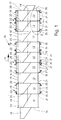
- the device shown here is predominantly commercial Laundries used continuous washing machine 10.
- items of laundry not shown in the figures are washed in batches, rinsed and treated if necessary.
- the continuous washing machine 10 has an elongated inner drum 11 which a horizontal longitudinal central axis 12 can be driven to rotate.
- the inner drum 11 of the Continuous washing machine 10 is divided into different treatment chambers 13 different zones for the treatment of the laundry items are defined. For example it is a prewash zone, a rinse zone, a rinse zone and, if appropriate a post-treatment zone.
- the individual treatment chambers 13 are in the treatment direction 14, which runs in the direction of the longitudinal central axis 12 of the inner drum 11, successively arranged in the inner drum 11 of the continuous washing machine 10.
- the number of successive treatment chambers 13 per zone can be vary in size and performance of the continuous washing machine 10.
- In front of an input end 15 on the left of FIG. 1 of the continuous washing machine 10 is a Input funnel 16 arranged.
- the right end 17 of the inner drum in FIG. 1 11 is assigned to a discharge chute 18.
- the one-piece inner drum 11 is formed, among other things, from cylindrical drum sections 19.
- Each drum section 19 serves to form a treatment chamber 13.
- the walls of the drum sections 19 can be completely or partially permeable to liquids be formed, namely have corresponding perforation holes.
- Between the individual drum sections 19 to form the treatment chambers 13 are in a vertical plane running perpendicular to the longitudinal central axis 12 lying circular blanks 20 arranged.
- the round plates 20 are with the end faces of the cylindrical drum sections 19 connected, preferably liquid-tight welded.
- the discs 20 have an outer diameter that is larger than that Outside diameter of the cylindrical shells of the drum sections 19 is such that a circular ring section 21 between two successive treatment chambers 13 each blank 20 outwards opposite the cylindrical surface of the inner drum 11 stands out.
- the inner drum 11 is in the area of some treatment chambers 13 surrounded by a fixed, liquid-tight outer drum 22.
- the outer drum 22 is assigned to the inner drum 11 at a standstill.
- the Outer drum 22 only assigned to parts of the inner drum 11, namely only certain ones Treatment chambers 13 of the inner drum 11.
- Between the larger in diameter Outer drum 22 and the inner drum 11 are receiving spaces 23 for liquid which is completely or partially permeable to liquid at least in the areas of the outer drum 22 Inner drum 11 provided.
- the outer drum 22 is formed from individual outer drum sections 24.
- the diameter of the cylindrical outer drum portion 24 is slightly larger than the outer diameter of the round plates 20 between two drum sections 19 of the inner drum 11.
- the length of the cylindrical outer drum sections 24 is slightly smaller than the distance between two round plates 20 opposite sides of the respective treatment chamber 13. This creates between two facing, circular end faces 25 successively Outer drum sections 24 a space 26.
- the cylindrical outer drum sections 24 ends directly at the opposite, circular End faces 25.
- the end faces 25 of the outer drum sections 24 are consequently at not particularly designed in any way, in particular not with the invention Provide end pieces or connecting pieces.
- the end faces 25 go accordingly smooth and smooth on the cylindrical outer drum section 24.
- each outer drum section 24 is outside of two ring flanges 27 surrounded.
- the two preferably identical ring flanges 27 each outer drum portion 24 are spaced one from the respective End face 25 outgoing edge portion 28 of the cylindrical shell is arranged.
- the Distances of the ring flanges 27 from the end faces 25 are each the same size.
- the ring flanges 27 are with the cylindrical outer surface of the outer drum section 24 connected, and preferably welded, this weld spot or can take place in some areas, so it does not have to be liquid-tight.
- Adjacent outer drum sections 24 are on ring flanges facing each other 27 connected to each other. Serve with preferably even intervals the circumference of the ring flanges 27 distributed screw connections 29. Between each other connected ring flanges 27, spacers are arranged. In the shown Embodiment (Fig. 6), these are spacer sleeves 30. These are supported on the side faces of the ring flanges facing each other connecting outer drum sections 24 and thereby place the distance between the outer drum sections 24, in particular the mutually facing end faces 25 of the same, and thus the width of the space 26 fixed.
- the respective Spacer sleeve 30 extends a screw bolt 31 with a nut 32, with which the respective screw connection 29 is closed and the two ring flanges 27 of presses on both sides against the respective spacer sleeve 30.
- the outer drum 22 is sealed against the inner drum 11, specifically in a liquid-tight manner.
- the sealing takes place in such a way that not only the exposed outer end faces 25 of the outer drum sections 24 are sealed, rather, also between successive outer drum sections 24 seals are located, creating a liquid-tight seal not just the treatment chambers 13 outwards, but also between the treatment chambers 13 he follows.
- the sealing of the treatment chambers 13 against the inner drum 11 the outer drum sections 24 are carried out by two in the exemplary embodiment shown different seals 33 and 34.
- the seals 33 serve to seal one free end face 25 at a respective lateral end of an outer outer drum section 24 of the outer drum 22 opposite the inner drum 11.
- With the Seals 34 provide a seal between two successive outer drum sections 24 of the outer drum 22 on the one hand and between the outer drum 22 and the inner drum 11 on the other hand.
- the seals 33 and 34 are made of an elastic material, for example rubber or an elastomer, the rubber or elastomer optionally being formed with Reinforcing inserts can be provided.
- the seals 33 and 34 are either endlessly cylindrical or out around the respective outer drum section 24 a finite strand is formed, which is ring-shaped around the relevant face 25 of the respective outer drum portion 24 is wrapped around, the ends of the seals 33, 34 sealed together and can be made endless.
- the seals 33 arranged at the free ends of the outer drum 22 have via a cylindrical sealing section 35 and a sealing means integrally molded thereon, which in the exemplary embodiment shown is a sealing lip 36.
- the sealing lip 36 is provided with a round blank 20 of the inner drum 11 assigned to it facing ends of the sealing portion 35 connected.
- the sealing lip 36 has a flat V-shaped cross section. A pointing away from the sealing section 35 Circumferential free end of the sealing lip forms a sealing edge 37 which on the in Vertical wall surface 38 of the round blank 20 facing the space 26 below Prestressing and thus sealing.
- sealing lip 36 lies in the at least partially filled with liquid Gap 26 between the inner drum 11 and the outer drum 22 and consequently by the pressure of the liquid in the intermediate space 26 with the sealing edge 37 pressed against the wall surface 38 to increase the sealing effect.
- the sealing portion 35 of the seal is cylindrical and dimensioned so that it preferably with bias the outer drum section 24 in the respective End side 25 outgoing edge section 28 surrounds from the outside in a ring.
- the Sealing section 35 is dimensioned in length so that it is at a distance from the Ring flange 27 on the side of the outer drum section provided with the seal 33 24 is located. This makes it possible to seal 33 with Sealing section 35 in the direction of the longitudinal central axis 12 of the inner drum 11 on the To shift edge section 28 of outer drum section 24, in such a way that that the sealing edge 37 of the sealing lip 36 with sufficient preload on the Wall surface 38 of the blank 20 abuts.
- the seal 34 between two successive outer drum sections 24 connects facing end faces 25 of two adjacent outer drum sections 24.
- the seal 34 is longer than the seal 33 cylindrical portion 39 provided.
- the cylindrical portion 39 extends from Edge section 28 of an outer drum section 24 to the edge section 28 of the adjacent outer drum section 24 (Fig. 2).
- the cylindrical one Section 39 of the gasket 34 over located at its opposite ends Sealing sections 40.
- the cylindrical Section 39 has a central section 41.
- the middle section 41 lying between the sealing sections 40 is located in the area of the space 26 between mutually facing End faces 25 of adjacent outer drum sections 24.
- At the central section 41 of the one-piece cylinder section 39 is also integrally formed on a sealing lip 42.
- the sealing lip 42 corresponds to the sealing lip 36.
- the sealing lip 42 extends in an annular manner through the intermediate space 26 and lies with a sealing edge 43 on one Wall surface 44 of the blank 20 between adjacent treatment chambers 13, which by the outer drum sections 24 connected by the seal 34 are surrounded, sealing under elastic pretension.
- the only sealing lip 42 of the seal 34 is sufficient to exchange liquid between the receiving spaces 23 between the inner drum 11 and the outer drum 22 of adjacent treatment chambers 13 to be avoided entirely or at least largely. Is the liquid level in the recording room 23, in which the sealing lip 42 of the seal 34 is located (left receiving space 23 2), higher than in the adjacent receiving space 23 (right receiving space 23 in Fig.
- the cylindrical section 39 is adjacent on mutually facing edge sections 28 Outer drum sections 24 serve to close the space 26 between the to seal adjacent outer drum sections 24 in a liquid-tight manner.
- the seal 34 in particular the cylindrical section 39 of the same, however, there are bearing deviations across the space 26 of the adjacent outer drum sections 24 or movements thereof during the operation of the continuous washing machine 10 balanced.
- An overuse the seal 34 is through the screw 29 between adjacent Outer drum sections 24 prevented. Transfer these screw connections 29 mechanical forces between adjacent outer drum sections 24, so that the cylindrical portion 39 of the seal 34 for connecting and sealing adjacent Outer drum sections 24 remains mechanically essentially unloaded.
- the cylindrical portion 39 of the seal 34 thus only takes on the task intended for it the sealing connection of the outer drum sections 24 true.
- the seals 33 and 34 are on the corresponding end faces 25 of the outer drum sections 24 fixed and sealingly prestressed by tensioning straps 45.
- tensioning straps 45 are basically known in structure and function.
- the straps 45 can be in one piece.
- the straps 45 are preferably formed in several parts, for example from four detachable by clamping screws interconnected parts, each over a quarter of the Circumference of the respective seal 33, 34 or of the outer drum section 24 extend.
- the tensioning straps 45 are the sealing sections 35 and 40 of the seal 33, 34 assigned.
- the width of the tensioning straps 45 is preferably such that they cover that part of the sealing section 35 or 40 which is on the outside of the respective end face 25 outgoing edge section 28 of the relevant outer drum section 24 is present.
Landscapes
- Engineering & Computer Science (AREA)
- Textile Engineering (AREA)
- Detail Structures Of Washing Machines And Dryers (AREA)
- Main Body Construction Of Washing Machines And Laundry Dryers (AREA)
- Treatment Of Fiber Materials (AREA)
Applications Claiming Priority (2)
| Application Number | Priority Date | Filing Date | Title |
|---|---|---|---|
| DE10056358A DE10056358A1 (de) | 2000-11-14 | 2000-11-14 | Vorrichtung zur Nassbehandlung von Wäsche und Dichtung für eine derartige Vorrichtung |
| DE10056358 | 2000-11-14 |
Publications (3)
| Publication Number | Publication Date |
|---|---|
| EP1205590A2 true EP1205590A2 (fr) | 2002-05-15 |
| EP1205590A3 EP1205590A3 (fr) | 2004-01-21 |
| EP1205590B1 EP1205590B1 (fr) | 2005-12-28 |
Family
ID=7663236
Family Applications (1)
| Application Number | Title | Priority Date | Filing Date |
|---|---|---|---|
| EP01125021A Expired - Lifetime EP1205590B1 (fr) | 2000-11-14 | 2001-10-20 | Dispositif pour le traitement au mouillé du linge et étanchéité pour un tel dispositif |
Country Status (5)
| Country | Link |
|---|---|
| US (1) | US6796150B2 (fr) |
| EP (1) | EP1205590B1 (fr) |
| AT (1) | ATE314517T1 (fr) |
| DE (2) | DE10056358A1 (fr) |
| DK (1) | DK1205590T3 (fr) |
Cited By (2)
| Publication number | Priority date | Publication date | Assignee | Title |
|---|---|---|---|---|
| EP2963172A1 (fr) * | 2014-07-02 | 2016-01-06 | Herbert Kannegiesser GmbH | Dispositif destiné au traitement humide du linge |
| WO2017201541A1 (fr) | 2016-05-20 | 2017-11-23 | Pellerin Milnor Corporation | Tunnel à écoulement combiné |
Families Citing this family (9)
| Publication number | Priority date | Publication date | Assignee | Title |
|---|---|---|---|---|
| ES2329929T3 (es) * | 2005-02-11 | 2009-12-02 | Herbert Kannegiesser Gmbh | Procedimiento y dispositivo para el tratamiento en humedo de piezas de ropa. |
| DE102007023801A1 (de) * | 2007-05-21 | 2008-11-27 | Herbert Kannegiesser Gmbh | Verfahren zur Nassbehandlung von Wäschestücken |
| CN101787635A (zh) * | 2009-12-22 | 2010-07-28 | 江苏海狮机械集团有限公司 | 隧道洗涤机中洗涤仓的密封结构 |
| CN106544809B (zh) * | 2016-06-03 | 2019-08-09 | 颉保申光洗涤科技(上海)有限公司 | 水循环节能环保洗涤龙 |
| CN107794715B (zh) * | 2016-08-31 | 2024-02-20 | 宁国聚隆减速器有限公司 | 一种节水滚筒洗衣机的水循环装置 |
| CN110510129A (zh) * | 2019-08-02 | 2019-11-29 | 西安飞机工业(集团)有限责任公司 | 一种飞机口盖的导电密封方法和导电密封带 |
| US11795601B2 (en) * | 2020-11-10 | 2023-10-24 | Whirlpool Corporation | Maximizing the dry rate of clothes tumbling combination washer/dryer with a seal |
| US11846059B2 (en) | 2021-01-04 | 2023-12-19 | Whirlpool Corporation | Controlling process air bypass around the drum in combo wash-dry system |
| CN116829778A (zh) | 2021-07-20 | 2023-09-29 | 佩莱若林·米尔诺公司 | 隧道式清洗机 |
Family Cites Families (23)
| Publication number | Priority date | Publication date | Assignee | Title |
|---|---|---|---|---|
| US1722470A (en) * | 1924-04-02 | 1929-07-30 | James H Jones | Washing machine |
| US2628461A (en) * | 1952-01-10 | 1953-02-17 | Moses D Heyman | Machine for washing mica pieces and the like |
| US3103802A (en) * | 1960-04-22 | 1963-09-17 | William Edlich | Washing machine |
| US3219969A (en) * | 1960-09-19 | 1965-11-23 | Benjamin L Snavely | Electroacoustic transducer and driving circuit therefor |
| US3247690A (en) * | 1962-04-11 | 1966-04-26 | Leo M Kahn | Clothes and fabric processing machine |
| US3815257A (en) * | 1973-04-04 | 1974-06-11 | Challenge Cook Bros Inc | Continuous laundry dryer |
| DE7441076U (de) * | 1974-12-10 | 1975-10-09 | Engelhardt & Foerster | Du rchlauf waschmaschine |
| DE2606350C2 (de) * | 1975-02-21 | 1985-10-17 | Ernst 4000 Düsseldorf Hugenbruch | Trommelmaschine mit mehreren Einzeltrommelmaschinen |
| DE2527729A1 (de) * | 1975-06-21 | 1977-01-13 | Karl Schaper | Durchlaufwaschmaschine |
| AT346271B (de) * | 1977-02-25 | 1978-11-10 | Poensgen & Sulzmann Gmbh Geb | Durchlauftrommelmaschine zum behandeln von textilgutposten |
| US4156358A (en) * | 1977-11-28 | 1979-05-29 | Firma Gebr. Poensgen & Sulzmann Gmbh | Drum for the wet treatment of materials |
| US4236393A (en) * | 1979-07-19 | 1980-12-02 | Pellerin Milnor Corporation | Continuous tunnel batch washer |
| DE3337236A1 (de) * | 1983-10-13 | 1985-04-25 | Mollerus, Alexander, 7128 Lauffen | Schleuse fuer tunnel-waschmaschine |
| DE3607119A1 (de) * | 1986-03-05 | 1987-09-17 | Kleindienst Gmbh | Postenwaschmaschine |
| DE3631866A1 (de) * | 1986-09-19 | 1988-03-31 | Transferon Waeschereimasch | Postendurchlaufwaschmaschine |
| DE3710033C2 (de) * | 1987-03-27 | 1994-10-20 | Transferon Waeschereimasch | Posten - Durchlaufwaschmaschine sowie Verfahren zu deren Herstellung |
| DE3819238C2 (de) * | 1988-06-06 | 1996-10-17 | Boewe Passat Reinigung | Waschmaschine |
| DE3903458A1 (de) * | 1989-02-06 | 1990-08-16 | Lavatec Waeschereimaschinen Gm | Durchlauf-postenwaschmaschine |
| DE4106621A1 (de) * | 1991-02-27 | 1992-09-03 | Effma Waeschereitechnik & Masc | Durchlauf-waschmaschine und hierfuer geeignete dichtung |
| JPH04367697A (ja) * | 1991-06-17 | 1992-12-18 | Sanyo Electric Co Ltd | 衣類乾燥機 |
| DE4238358A1 (de) * | 1992-11-13 | 1994-05-19 | Boewe Passat Reinigung | Waschmaschine |
| ES2107338B1 (es) * | 1994-09-15 | 1998-07-01 | Girbau Sa | Maquina lavadora |
| DE19941073A1 (de) * | 1999-08-30 | 2001-03-01 | Pharmagg Systemtechnik Gmbh | Verfahren und Vorrichtung zum Naßbehandeln, insbesondere Waschen, von Wäschestücken |
-
2000
- 2000-11-14 DE DE10056358A patent/DE10056358A1/de not_active Withdrawn
-
2001
- 2001-10-20 EP EP01125021A patent/EP1205590B1/fr not_active Expired - Lifetime
- 2001-10-20 DK DK01125021T patent/DK1205590T3/da active
- 2001-10-20 DE DE50108528T patent/DE50108528D1/de not_active Expired - Lifetime
- 2001-10-20 AT AT01125021T patent/ATE314517T1/de not_active IP Right Cessation
- 2001-11-05 US US10/010,513 patent/US6796150B2/en not_active Expired - Lifetime
Cited By (5)
| Publication number | Priority date | Publication date | Assignee | Title |
|---|---|---|---|---|
| EP2963172A1 (fr) * | 2014-07-02 | 2016-01-06 | Herbert Kannegiesser GmbH | Dispositif destiné au traitement humide du linge |
| US9556550B2 (en) | 2014-07-02 | 2017-01-31 | Herbert Kannegiesser Gmbh | Device for the wet-treatment of laundry |
| WO2017201541A1 (fr) | 2016-05-20 | 2017-11-23 | Pellerin Milnor Corporation | Tunnel à écoulement combiné |
| EP3458637A4 (fr) * | 2016-05-20 | 2020-01-08 | Pellerin Milnor Corporation | Tunnel à écoulement combiné |
| US11225742B2 (en) | 2016-05-20 | 2022-01-18 | Pellerin Milnor Corporation | Combination flow tunnel |
Also Published As
| Publication number | Publication date |
|---|---|
| EP1205590A3 (fr) | 2004-01-21 |
| DK1205590T3 (da) | 2006-05-01 |
| US20020083742A1 (en) | 2002-07-04 |
| DE50108528D1 (de) | 2006-02-02 |
| US6796150B2 (en) | 2004-09-28 |
| EP1205590B1 (fr) | 2005-12-28 |
| ATE314517T1 (de) | 2006-01-15 |
| DE10056358A1 (de) | 2002-05-23 |
Similar Documents
| Publication | Publication Date | Title |
|---|---|---|
| DE10117235B4 (de) | Kartuschenanordung für eine Raupenkette | |
| EP0123721B1 (fr) | Dispositif à filtre à manche avec nettoyage à air comprimé | |
| EP1205590B1 (fr) | Dispositif pour le traitement au mouillé du linge et étanchéité pour un tel dispositif | |
| DE102011116631A1 (de) | Linearbewegungsvorrichtung mit einer Verdrehsicherung, umfassend einen langgestreckten Gleitbelag | |
| EP2024653A2 (fr) | Palier à roulement avec deux bagues internes et un agencement d'étanchéité pour l'étanchéité du joint de séparation entre les bagues internes | |
| DE2817968A1 (de) | Kettentrommel | |
| EP2986442B1 (fr) | Cylindre presseur | |
| WO2014170080A1 (fr) | Cylindre presseur | |
| WO2002000320A1 (fr) | Module filtrant | |
| CH688365A5 (de) | Misch- und Knetvorrichtung. | |
| DE3333130C2 (fr) | ||
| DE3819238C2 (de) | Waschmaschine | |
| EP1856963A1 (fr) | Rouleau agricole de sol | |
| DE102009041105A1 (de) | Tragrolle mit zusätzlichem Wetterschild mit Axial-Dichtung | |
| EP0706001A1 (fr) | Joint à lèvre radiale | |
| EP0491124B1 (fr) | Palier | |
| DE102004012396A1 (de) | Elastische Wellenkupplung | |
| WO2008006232A1 (fr) | Rouleau de nettoyage | |
| EP1420103B1 (fr) | Séchoir, en particulier séchoir à linge | |
| EP2963172B1 (fr) | Dispositif destiné au traitement humide du linge | |
| DE2235599A1 (de) | Durchlaufwaschmaschine | |
| DE102011111706A1 (de) | Zellenradschleuse | |
| EP4133194A1 (fr) | Ensemble joint d'étanchéité avec unité d'étanchéité | |
| DE3241080C2 (fr) | ||
| EP0172922A1 (fr) | Roue dentée, en particulier pour véhicules à chenille |
Legal Events
| Date | Code | Title | Description |
|---|---|---|---|
| PUAI | Public reference made under article 153(3) epc to a published international application that has entered the european phase |
Free format text: ORIGINAL CODE: 0009012 |
|
| AK | Designated contracting states |
Kind code of ref document: A2 Designated state(s): AT BE CH CY DE DK ES FI FR GB GR IE IT LI LU MC NL PT SE TR |
|
| AX | Request for extension of the european patent |
Free format text: AL;LT;LV;MK;RO;SI |
|
| PUAL | Search report despatched |
Free format text: ORIGINAL CODE: 0009013 |
|
| AK | Designated contracting states |
Kind code of ref document: A3 Designated state(s): AT BE CH CY DE DK ES FI FR GB GR IE IT LI LU MC NL PT SE TR |
|
| AX | Request for extension of the european patent |
Extension state: AL LT LV MK RO SI |
|
| 17P | Request for examination filed |
Effective date: 20040302 |
|
| 17Q | First examination report despatched |
Effective date: 20040811 |
|
| AKX | Designation fees paid |
Designated state(s): AT BE CH CY DE DK ES FI FR GB GR IE IT LI LU MC NL PT SE TR |
|
| GRAP | Despatch of communication of intention to grant a patent |
Free format text: ORIGINAL CODE: EPIDOSNIGR1 |
|
| GRAS | Grant fee paid |
Free format text: ORIGINAL CODE: EPIDOSNIGR3 |
|
| GRAA | (expected) grant |
Free format text: ORIGINAL CODE: 0009210 |
|
| AK | Designated contracting states |
Kind code of ref document: B1 Designated state(s): AT BE CH CY DE DK ES FI FR GB GR IE IT LI LU MC NL PT SE TR |
|
| PG25 | Lapsed in a contracting state [announced via postgrant information from national office to epo] |
Ref country code: FI Free format text: LAPSE BECAUSE OF FAILURE TO SUBMIT A TRANSLATION OF THE DESCRIPTION OR TO PAY THE FEE WITHIN THE PRESCRIBED TIME-LIMIT Effective date: 20051228 Ref country code: IE Free format text: LAPSE BECAUSE OF FAILURE TO SUBMIT A TRANSLATION OF THE DESCRIPTION OR TO PAY THE FEE WITHIN THE PRESCRIBED TIME-LIMIT Effective date: 20051228 Ref country code: IT Free format text: LAPSE BECAUSE OF FAILURE TO SUBMIT A TRANSLATION OF THE DESCRIPTION OR TO PAY THE FEE WITHIN THE PRESCRIBED TIME-LIMIT;WARNING: LAPSES OF ITALIAN PATENTS WITH EFFECTIVE DATE BEFORE 2007 MAY HAVE OCCURRED AT ANY TIME BEFORE 2007. THE CORRECT EFFECTIVE DATE MAY BE DIFFERENT FROM THE ONE RECORDED. Effective date: 20051228 |
|
| REG | Reference to a national code |
Ref country code: GB Ref legal event code: FG4D Free format text: NOT ENGLISH |
|
| REG | Reference to a national code |
Ref country code: CH Ref legal event code: EP |
|
| REG | Reference to a national code |
Ref country code: IE Ref legal event code: FG4D Free format text: LANGUAGE OF EP DOCUMENT: GERMAN |
|
| REF | Corresponds to: |
Ref document number: 50108528 Country of ref document: DE Date of ref document: 20060202 Kind code of ref document: P |
|
| REG | Reference to a national code |
Ref country code: CH Ref legal event code: NV Representative=s name: R. A. EGLI & CO. PATENTANWAELTE |
|
| PG25 | Lapsed in a contracting state [announced via postgrant information from national office to epo] |
Ref country code: SE Free format text: LAPSE BECAUSE OF FAILURE TO SUBMIT A TRANSLATION OF THE DESCRIPTION OR TO PAY THE FEE WITHIN THE PRESCRIBED TIME-LIMIT Effective date: 20060328 Ref country code: GR Free format text: LAPSE BECAUSE OF FAILURE TO SUBMIT A TRANSLATION OF THE DESCRIPTION OR TO PAY THE FEE WITHIN THE PRESCRIBED TIME-LIMIT Effective date: 20060328 |
|
| PG25 | Lapsed in a contracting state [announced via postgrant information from national office to epo] |
Ref country code: ES Free format text: LAPSE BECAUSE OF FAILURE TO SUBMIT A TRANSLATION OF THE DESCRIPTION OR TO PAY THE FEE WITHIN THE PRESCRIBED TIME-LIMIT Effective date: 20060408 |
|
| GBT | Gb: translation of ep patent filed (gb section 77(6)(a)/1977) |
Effective date: 20060405 |
|
| REG | Reference to a national code |
Ref country code: DK Ref legal event code: T3 |
|
| PG25 | Lapsed in a contracting state [announced via postgrant information from national office to epo] |
Ref country code: PT Free format text: LAPSE BECAUSE OF FAILURE TO SUBMIT A TRANSLATION OF THE DESCRIPTION OR TO PAY THE FEE WITHIN THE PRESCRIBED TIME-LIMIT Effective date: 20060529 |
|
| REG | Reference to a national code |
Ref country code: IE Ref legal event code: FD4D |
|
| ET | Fr: translation filed | ||
| PG25 | Lapsed in a contracting state [announced via postgrant information from national office to epo] |
Ref country code: MC Free format text: LAPSE BECAUSE OF NON-PAYMENT OF DUE FEES Effective date: 20061031 |
|
| PLBE | No opposition filed within time limit |
Free format text: ORIGINAL CODE: 0009261 |
|
| STAA | Information on the status of an ep patent application or granted ep patent |
Free format text: STATUS: NO OPPOSITION FILED WITHIN TIME LIMIT |
|
| 26N | No opposition filed |
Effective date: 20060929 |
|
| PGFP | Annual fee paid to national office [announced via postgrant information from national office to epo] |
Ref country code: NL Payment date: 20071003 Year of fee payment: 7 |
|
| PG25 | Lapsed in a contracting state [announced via postgrant information from national office to epo] |
Ref country code: AT Free format text: LAPSE BECAUSE OF NON-PAYMENT OF DUE FEES Effective date: 20061020 |
|
| PGFP | Annual fee paid to national office [announced via postgrant information from national office to epo] |
Ref country code: CH Payment date: 20071015 Year of fee payment: 7 |
|
| PGFP | Annual fee paid to national office [announced via postgrant information from national office to epo] |
Ref country code: BE Payment date: 20071213 Year of fee payment: 7 |
|
| PG25 | Lapsed in a contracting state [announced via postgrant information from national office to epo] |
Ref country code: LU Free format text: LAPSE BECAUSE OF NON-PAYMENT OF DUE FEES Effective date: 20061020 Ref country code: TR Free format text: LAPSE BECAUSE OF FAILURE TO SUBMIT A TRANSLATION OF THE DESCRIPTION OR TO PAY THE FEE WITHIN THE PRESCRIBED TIME-LIMIT Effective date: 20051228 |
|
| PG25 | Lapsed in a contracting state [announced via postgrant information from national office to epo] |
Ref country code: CY Free format text: LAPSE BECAUSE OF FAILURE TO SUBMIT A TRANSLATION OF THE DESCRIPTION OR TO PAY THE FEE WITHIN THE PRESCRIBED TIME-LIMIT Effective date: 20051228 |
|
| BERE | Be: lapsed |
Owner name: *PHARMAGG SYSTEMTECHNIK G.M.B.H. Effective date: 20081031 |
|
| REG | Reference to a national code |
Ref country code: CH Ref legal event code: PL |
|
| NLV4 | Nl: lapsed or anulled due to non-payment of the annual fee |
Effective date: 20090501 |
|
| PG25 | Lapsed in a contracting state [announced via postgrant information from national office to epo] |
Ref country code: NL Free format text: LAPSE BECAUSE OF NON-PAYMENT OF DUE FEES Effective date: 20090501 |
|
| PG25 | Lapsed in a contracting state [announced via postgrant information from national office to epo] |
Ref country code: BE Free format text: LAPSE BECAUSE OF NON-PAYMENT OF DUE FEES Effective date: 20081031 |
|
| PG25 | Lapsed in a contracting state [announced via postgrant information from national office to epo] |
Ref country code: LI Free format text: LAPSE BECAUSE OF NON-PAYMENT OF DUE FEES Effective date: 20081031 Ref country code: CH Free format text: LAPSE BECAUSE OF NON-PAYMENT OF DUE FEES Effective date: 20081031 |
|
| PGFP | Annual fee paid to national office [announced via postgrant information from national office to epo] |
Ref country code: FR Payment date: 20101020 Year of fee payment: 10 |
|
| PGFP | Annual fee paid to national office [announced via postgrant information from national office to epo] |
Ref country code: GB Payment date: 20101020 Year of fee payment: 10 Ref country code: IT Payment date: 20101021 Year of fee payment: 10 |
|
| PGFP | Annual fee paid to national office [announced via postgrant information from national office to epo] |
Ref country code: DK Payment date: 20111011 Year of fee payment: 11 |
|
| GBPC | Gb: european patent ceased through non-payment of renewal fee |
Effective date: 20111020 |
|
| REG | Reference to a national code |
Ref country code: FR Ref legal event code: ST Effective date: 20120629 |
|
| PG25 | Lapsed in a contracting state [announced via postgrant information from national office to epo] |
Ref country code: FR Free format text: LAPSE BECAUSE OF NON-PAYMENT OF DUE FEES Effective date: 20111102 Ref country code: GB Free format text: LAPSE BECAUSE OF NON-PAYMENT OF DUE FEES Effective date: 20111020 |
|
| REG | Reference to a national code |
Ref country code: DE Ref legal event code: R082 Ref document number: 50108528 Country of ref document: DE Representative=s name: MEISSNER, BOLTE & PARTNER GBR, DE |
|
| REG | Reference to a national code |
Ref country code: DE Ref legal event code: R082 Ref document number: 50108528 Country of ref document: DE Representative=s name: MEISSNER BOLTE PATENTANWAELTE RECHTSANWAELTE P, DE Effective date: 20130405 Ref country code: DE Ref legal event code: R082 Ref document number: 50108528 Country of ref document: DE Representative=s name: MEISSNER, BOLTE & PARTNER GBR, DE Effective date: 20130405 Ref country code: DE Ref legal event code: R081 Ref document number: 50108528 Country of ref document: DE Owner name: HERBERT KANNEGIESSER GMBH, DE Free format text: FORMER OWNER: PHARMAGG SYSTEMTECHNIK GMBH, 27318 HOYA, DE Effective date: 20130405 |
|
| REG | Reference to a national code |
Ref country code: DK Ref legal event code: EBP |
|
| PG25 | Lapsed in a contracting state [announced via postgrant information from national office to epo] |
Ref country code: IT Free format text: LAPSE BECAUSE OF NON-PAYMENT OF DUE FEES Effective date: 20121020 |
|
| PG25 | Lapsed in a contracting state [announced via postgrant information from national office to epo] |
Ref country code: DK Free format text: LAPSE BECAUSE OF NON-PAYMENT OF DUE FEES Effective date: 20121031 |
|
| PGFP | Annual fee paid to national office [announced via postgrant information from national office to epo] |
Ref country code: DE Payment date: 20200930 Year of fee payment: 20 |
|
| REG | Reference to a national code |
Ref country code: DE Ref legal event code: R071 Ref document number: 50108528 Country of ref document: DE |