EP1205800A1 - Entwicklung von fotografischen Materialien - Google Patents
Entwicklung von fotografischen Materialien Download PDFInfo
- Publication number
- EP1205800A1 EP1205800A1 EP20010203841 EP01203841A EP1205800A1 EP 1205800 A1 EP1205800 A1 EP 1205800A1 EP 20010203841 EP20010203841 EP 20010203841 EP 01203841 A EP01203841 A EP 01203841A EP 1205800 A1 EP1205800 A1 EP 1205800A1
- Authority
- EP
- European Patent Office
- Prior art keywords
- processing
- solution
- circulation system
- chamber
- processing solution
- Prior art date
- Legal status (The legal status is an assumption and is not a legal conclusion. Google has not performed a legal analysis and makes no representation as to the accuracy of the status listed.)
- Withdrawn
Links
- 239000000463 material Substances 0.000 title claims description 19
- 238000000034 method Methods 0.000 claims abstract description 11
- 238000001914 filtration Methods 0.000 claims abstract description 3
- 230000008569 process Effects 0.000 description 3
- 238000004061 bleaching Methods 0.000 description 2
- 230000008859 change Effects 0.000 description 2
- 239000000126 substance Substances 0.000 description 2
- 238000005406 washing Methods 0.000 description 2
- 230000000712 assembly Effects 0.000 description 1
- 238000000429 assembly Methods 0.000 description 1
- 230000008901 benefit Effects 0.000 description 1
- 238000004140 cleaning Methods 0.000 description 1
- 239000000356 contaminant Substances 0.000 description 1
- 238000011109 contamination Methods 0.000 description 1
- 238000001035 drying Methods 0.000 description 1
- 230000000694 effects Effects 0.000 description 1
- 238000005265 energy consumption Methods 0.000 description 1
- 238000011010 flushing procedure Methods 0.000 description 1
- 238000010438 heat treatment Methods 0.000 description 1
- 238000012423 maintenance Methods 0.000 description 1
- 238000012986 modification Methods 0.000 description 1
- 230000004048 modification Effects 0.000 description 1
- 239000002245 particle Substances 0.000 description 1
- 230000009467 reduction Effects 0.000 description 1
Images

Classifications
-
- G—PHYSICS
- G03—PHOTOGRAPHY; CINEMATOGRAPHY; ANALOGOUS TECHNIQUES USING WAVES OTHER THAN OPTICAL WAVES; ELECTROGRAPHY; HOLOGRAPHY
- G03D—APPARATUS FOR PROCESSING EXPOSED PHOTOGRAPHIC MATERIALS; ACCESSORIES THEREFOR
- G03D3/00—Liquid processing apparatus involving immersion; Washing apparatus involving immersion
- G03D3/08—Liquid processing apparatus involving immersion; Washing apparatus involving immersion having progressive mechanical movement of exposed material
- G03D3/13—Liquid processing apparatus involving immersion; Washing apparatus involving immersion having progressive mechanical movement of exposed material for long films or prints in the shape of strips, e.g. fed by roller assembly
- G03D3/132—Liquid processing apparatus involving immersion; Washing apparatus involving immersion having progressive mechanical movement of exposed material for long films or prints in the shape of strips, e.g. fed by roller assembly fed by roller assembly
-
- G—PHYSICS
- G03—PHOTOGRAPHY; CINEMATOGRAPHY; ANALOGOUS TECHNIQUES USING WAVES OTHER THAN OPTICAL WAVES; ELECTROGRAPHY; HOLOGRAPHY
- G03D—APPARATUS FOR PROCESSING EXPOSED PHOTOGRAPHIC MATERIALS; ACCESSORIES THEREFOR
- G03D3/00—Liquid processing apparatus involving immersion; Washing apparatus involving immersion
- G03D3/02—Details of liquid circulation
- G03D3/06—Liquid supply; Liquid circulation outside tanks
-
- Y—GENERAL TAGGING OF NEW TECHNOLOGICAL DEVELOPMENTS; GENERAL TAGGING OF CROSS-SECTIONAL TECHNOLOGIES SPANNING OVER SEVERAL SECTIONS OF THE IPC; TECHNICAL SUBJECTS COVERED BY FORMER USPC CROSS-REFERENCE ART COLLECTIONS [XRACs] AND DIGESTS
- Y10—TECHNICAL SUBJECTS COVERED BY FORMER USPC
- Y10T—TECHNICAL SUBJECTS COVERED BY FORMER US CLASSIFICATION
- Y10T137/00—Fluid handling
- Y10T137/8593—Systems
- Y10T137/85954—Closed circulating system
Definitions
- This invention relates to an apparatus for processing photographic material.
- the invention relates to a method of reducing the volume of low volume processors.
- photosensitive material such as photographic film
- steps such as developing, bleaching, fixing, washing and drying.
- a continuous web of film or cut sheet of film is sequentially conveyed through a series of stations or tanks, with each one containing a different processing solution appropriate to the process step at that stage.
- a large photofinishing apparatus utilises rack and tank configurations that contain approximately 100 litres of each processing solution.
- a smaller photofinishing apparatus such as a minilab may have tanks which contain less than 10 litres of processing solution. However these tanks have generally been replaced by low volume thin tanks in which the material to be processed passes through a narrow processing channel.
- Such a processing apparatus is disclosed in, for example, US 5420658. This document discloses a low volume photographic material processing apparatus that utilises a narrow substantially horizontal processing channel. The channel has an upturned entrance and exit to contain the processing solution within the channel. The processing apparatus will contain a smaller volume of processing solution than was previously used in regular sized processing tanks.
- an apparatus for processing photographic material comprising a processing chamber through which the material to be processed passes, said chamber having an inlet for processing solution and an outlet for processing solution, a circulation system connecting the inlet and the outlet outside of the chamber, a buffer reservoir of processing solution for supplying processing solution to the circulation system and means for circulating the processing solution through the chamber and circulation system, filter means for filtering the processing solution being located external to the circulation system such that the solution is filtered only on entry to or exit from the circulation system.
- the invention further provides a method of processing photographic material comprising the steps of providing a processing chamber and associated circulation system with a small volume of processing solution from a reservoir of processing solution, passing the photographic material through the processing chamber, circulating the processing solution through the chamber and the system, and returning the solution to the reservoir, the processing solution being filtered as it is provided to the circulation system and/or on exit therefrom.
- the apparatus of the invention allows simple flush cleaning of the processing chamber. This reduces contamination of the processing chamber by previously used solutions.
- the solution may be cleaned before processing or after processing depending on the position of the filter within the system. If the filter is located within the solution supply cartridge particles will settle to the bottom, extending the life of the filter.
- Such an embodiment also reduces the maintenance required. Furthermore, the operator never has to handle a wet filter.
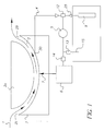
- a circulating system 4 fluidly connects the inlet port 7 and outlet port 30 externally of the chamber 2.
- the circulating system 4 includes a pump 5 and a heater 6.
- the heater 6 is positioned just prior, in the direction of flow, to the inlet port 7 of the processing channel 3.
- a valve 14 is provided between the pump 5 and the heater 6.
- the reservoir may be in the form of a cartridge.
- the cartridge 10 is provided with two pipes 15 and 25.
- the cartridge also includes a filter 9. The filter removes contaminants and debris that may be contained in the processing solution.
- a valve 13 is provided within the pipe 15.
- a valve 12 is located at the pipe 25 to control flow from the reservoir 10 to the circulating system 4.
- valve 12 In order to provide processing solution in the processing channel 3 the pump 5 is switched on and the valve 12 is activated to allow flow of solution from the supply cartridge 10. This flow from the supply cartridge passes through the filter 9 and into the circulating system 4. Valve 13 in the pipe 15 is closed to prevent the solution returning immediately to the supply cartridge. Valve 14 is open so that the processing solution passes through the circulating system 4 and thus to inlet port 7 and through the channel 3. When the system is full valve 12 is activated to cut off flow from the cartridge 10. The solution in the system 4 is pumped around the system by pump 5 and is heated by heater 6. The solution is heated to a predetermined temperature and is then maintained at this temperature.
- the volume of solution pumped around the system is small compared to the amount of solution in the full supply reservoir 10.
- the solution is reused as it is returned to the supply reservoir after processing takes place.
- the material to be processed passes through the processing channel 3 at a given speed, in the direction shown by the arrow in Figure 1.
- the film 1 may be in a cut sheet or roll format.
- the processing solution is circulated in and through the processing channel by pump 5.
- the solution is pumped around the circulating system 4 in the direction of arrow 11.
- processing solution is returned to the cartridge 10.
- valve 14 is closed and valve 13 is opened.
- the processing channel 3 can be flushed clean by repeating the filling and emptying of the circulating system a few times. It may be advantageous, and will also reduce energy consumption, to turn off the heater 6 during the flushing operation.
- the processing channel may be left empty or full as desired.
- the supply cartridge 22 shown in Figure 2 is connected to the circulating system 4 via pipe 23 and pipe 15.
- the cartridge 22 is a single entry supply cartridge, having only one exit/entrance point for pipe 23 and pipe 15.
- a valve 21 couples the cartridge to the pipes 23 and 15.
- the filter 9 is located in the supply pipe 23. In an alternative embodiment, not shown, the filter 9 may be located in the pipe 15.
- the cartridge may be of a plug-in Kodak® SM type chemical cartridge.
- valve 12 is activated to allow flow of solution from the supply cartridge 22. This flow from the supply cartridge passes through the filter 9 and into the circulating system 4. Valve 13 in the pipe 15 is closed to prevent the solution returning immediately to the supply cartridge. Valve 14 is open so that the processing solution passes through the circulating system 4 and thus to inlet port 7 and through the processing channel 3. When the system is full valve 12 is activated to cut off flow from the cartridge 22. The solution in the system 4 is pumped around the system by pump 5 and is heated by heater 6. To enable the solution to return to the cartridge 22 valve 12 is closed and valve 13 is opened.
- the system and method described above is particularly suited for batch methods of solution management or where the solution is drained and filled between processing runs.
- the volume of the processing chamber can be significantly reduced. Approximately half a litre reduction in volume is achievable with the invention.
Landscapes
- Physics & Mathematics (AREA)
- General Physics & Mathematics (AREA)
- Photographic Processing Devices Using Wet Methods (AREA)
- Devices For Dispensing Beverages (AREA)
Applications Claiming Priority (2)
| Application Number | Priority Date | Filing Date | Title |
|---|---|---|---|
| GB0026948A GB0026948D0 (en) | 2000-11-03 | 2000-11-03 | Processing photographic material |
| GB0026948 | 2000-11-03 |
Publications (1)
| Publication Number | Publication Date |
|---|---|
| EP1205800A1 true EP1205800A1 (de) | 2002-05-15 |
Family
ID=9902534
Family Applications (1)
| Application Number | Title | Priority Date | Filing Date |
|---|---|---|---|
| EP20010203841 Withdrawn EP1205800A1 (de) | 2000-11-03 | 2001-10-11 | Entwicklung von fotografischen Materialien |
Country Status (4)
| Country | Link |
|---|---|
| US (1) | US6488421B2 (de) |
| EP (1) | EP1205800A1 (de) |
| CN (1) | CN1352411A (de) |
| GB (1) | GB0026948D0 (de) |
Cited By (1)
| Publication number | Priority date | Publication date | Assignee | Title |
|---|---|---|---|---|
| EP1507168A3 (de) * | 2003-08-13 | 2006-06-07 | Kodak Polychrome Graphics | Tankausgang für Entwickler in einer Druckplattenentwicklungsvorrichtung vom Immersionstyp |
Families Citing this family (2)
| Publication number | Priority date | Publication date | Assignee | Title |
|---|---|---|---|---|
| US8078086B2 (en) * | 2007-11-02 | 2011-12-13 | Seiko Epson Corporation | Liquid developer transport device and image forming apparatus |
| CN105170534A (zh) * | 2015-10-15 | 2015-12-23 | 京东方科技集团股份有限公司 | 一种清洗设备 |
Citations (3)
| Publication number | Priority date | Publication date | Assignee | Title |
|---|---|---|---|---|
| US4688917A (en) * | 1985-10-09 | 1987-08-25 | Agfa-Gevaert Ag | Device for wet processing of photographic films |
| EP0716343A1 (de) * | 1994-12-06 | 1996-06-12 | Konica Corporation | Automatische Behandlungsvorrichtung für lichtempfindliches photographisches Silberhalogenidmaterial |
| EP0833200A1 (de) * | 1996-09-30 | 1998-04-01 | Eastman Kodak Company | Photographisches Verarbeitungsgerät und Betriebsverfahren dazu |
Family Cites Families (28)
| Publication number | Priority date | Publication date | Assignee | Title |
|---|---|---|---|---|
| JPS6075316A (ja) | 1983-09-30 | 1985-04-27 | Dainippon Screen Mfg Co Ltd | 感光材自動現像機の現像液濾過フィルタ |
| JPS61112148A (ja) | 1984-11-06 | 1986-05-30 | Konishiroku Photo Ind Co Ltd | カラ−写真感光材料用自動現像機 |
| JPS62215955A (ja) | 1986-03-17 | 1987-09-22 | Konishiroku Photo Ind Co Ltd | 自動現像処理装置 |
| US4827109A (en) | 1987-02-18 | 1989-05-02 | Fuji Photo Film Co., Ltd. | Photographic printing system |
| US4804990A (en) | 1988-02-08 | 1989-02-14 | Eastman Kodak Company | Automatic liquid feed and circulation system for a photographic film processor |
| JPH01267649A (ja) | 1988-04-20 | 1989-10-25 | Fuji Photo Film Co Ltd | 感光材料処理装置 |
| JPH0786679B2 (ja) | 1988-08-08 | 1995-09-20 | 富士写真フイルム株式会社 | 現像機 |
| JPH02251956A (ja) | 1989-03-27 | 1990-10-09 | Fuji Photo Film Co Ltd | 感光材料処理装置 |
| JPH02253254A (ja) | 1989-03-28 | 1990-10-12 | Fuji Photo Film Co Ltd | 感光材料処理装置 |
| US5309191A (en) | 1992-03-02 | 1994-05-03 | Eastman Kodak Company | Recirculation, replenishment, refresh, recharge and backflush for a photographic processing apparatus |
| US5400106A (en) | 1993-05-03 | 1995-03-21 | Eastman Kodak Company | Automatic tray processor |
| US5353083A (en) | 1993-05-03 | 1994-10-04 | Eastman Kodak Company | Closed solution recirculation/shutoff system for an automatic tray processor |
| US5353088A (en) | 1993-05-03 | 1994-10-04 | Eastman Kodak Company | Automatic tray processor |
| US5353086A (en) | 1993-05-03 | 1994-10-04 | Eastman Kodak Company | Textured surface with canted channels for an automatic tray processor |
| US5381203A (en) | 1993-05-03 | 1995-01-10 | Eastman Kodak Company | Textured surface with canted channels for an automatic tray processor |
| US5389994A (en) | 1993-05-03 | 1995-02-14 | Eastman Kodak Company | Closed solution recirculation/shutoff system for an automatic tray processor |
| US5313243A (en) | 1993-05-03 | 1994-05-17 | Eastman Kodak Company | Counter cross flow for an automatic tray processor |
| US5420658A (en) | 1993-05-03 | 1995-05-30 | Eastman Kodak Company | Modular processing channel for an automatic tray processor |
| JP2988229B2 (ja) | 1993-11-22 | 1999-12-13 | ノーリツ鋼機株式会社 | 感光材料処理装置の処理液温度調整機構 |
| JPH0822111A (ja) | 1994-07-06 | 1996-01-23 | Noritsu Koki Co Ltd | 写真感光材料の自動現像処理装置 |
| JP3047773B2 (ja) | 1995-04-11 | 2000-06-05 | ノーリツ鋼機株式会社 | ストレーナ |
| GB2300492B (en) | 1995-05-04 | 1998-12-23 | Kodak Ltd | Processing of photographic materials |
| US5664253A (en) | 1995-09-12 | 1997-09-02 | Eastman Kodak Company | Stand alone photofinishing apparatus |
| US5761561A (en) | 1996-09-30 | 1998-06-02 | Eastman Kodak Company | Photographic processor and method of operation |
| JP3857374B2 (ja) | 1997-02-28 | 2006-12-13 | 富士フイルムホールディングス株式会社 | 感光材料処理装置 |
| JP3624651B2 (ja) | 1997-09-26 | 2005-03-02 | ノーリツ鋼機株式会社 | 写真現像処理装置 |
| US6105787A (en) | 1998-04-01 | 2000-08-22 | Malkin; Edward | Filtration device |
| FR2807423B1 (fr) * | 2000-04-05 | 2002-10-31 | Eastman Kodak Co | Installation de traitement d'eaux de lavage munie d'un dispositif de recyclage independant. |
-
2000
- 2000-11-03 GB GB0026948A patent/GB0026948D0/en not_active Ceased
-
2001
- 2001-10-11 EP EP20010203841 patent/EP1205800A1/de not_active Withdrawn
- 2001-10-25 US US10/032,997 patent/US6488421B2/en not_active Expired - Fee Related
- 2001-10-31 CN CN01137714A patent/CN1352411A/zh active Pending
Patent Citations (3)
| Publication number | Priority date | Publication date | Assignee | Title |
|---|---|---|---|---|
| US4688917A (en) * | 1985-10-09 | 1987-08-25 | Agfa-Gevaert Ag | Device for wet processing of photographic films |
| EP0716343A1 (de) * | 1994-12-06 | 1996-06-12 | Konica Corporation | Automatische Behandlungsvorrichtung für lichtempfindliches photographisches Silberhalogenidmaterial |
| EP0833200A1 (de) * | 1996-09-30 | 1998-04-01 | Eastman Kodak Company | Photographisches Verarbeitungsgerät und Betriebsverfahren dazu |
Cited By (1)
| Publication number | Priority date | Publication date | Assignee | Title |
|---|---|---|---|---|
| EP1507168A3 (de) * | 2003-08-13 | 2006-06-07 | Kodak Polychrome Graphics | Tankausgang für Entwickler in einer Druckplattenentwicklungsvorrichtung vom Immersionstyp |
Also Published As
| Publication number | Publication date |
|---|---|
| US6488421B2 (en) | 2002-12-03 |
| GB0026948D0 (en) | 2000-12-20 |
| CN1352411A (zh) | 2002-06-05 |
| US20020081119A1 (en) | 2002-06-27 |
Similar Documents
| Publication | Publication Date | Title |
|---|---|---|
| JP6607820B2 (ja) | フィルタ立ち上げ装置、処理液供給装置、治具ユニット、フィルタの立ち上げ方法 | |
| US5309191A (en) | Recirculation, replenishment, refresh, recharge and backflush for a photographic processing apparatus | |
| CA2121442C (en) | Automatic tray processor | |
| CA2088970A1 (en) | Rack and a tank for a photographic processing apparatus | |
| JP2726235B2 (ja) | 織物面のチャネルを有する感光材処理装置 | |
| US6488421B2 (en) | Processing photographic material | |
| KR20010005688A (ko) | 인쇄유니트에 인쇄잉크와 세척액을 공급하는 방법과 펌프유니트 | |
| US5452043A (en) | Rack and a tank for a photographic low volume thin tank insert for a rack and a tank photographic processing apparatus | |
| JP2928093B2 (ja) | モジュラー処理チャネルを有する感光材処理装置 | |
| US5353088A (en) | Automatic tray processor | |
| JP2928090B2 (ja) | 感光材処理装置 | |
| JP2002182356A (ja) | 写真材料の処理装置及び方法 | |
| JPH08171188A (ja) | 感光材料の処理装置 | |
| JPH06508225A (ja) | 感光材料の処理装置 | |
| EP0880072A1 (de) | Photographisches Entwicklungsgerät | |
| JPH09230566A (ja) | 写真処理方法および装置 | |
| EP1341037A1 (de) | Gegenstromwaschung | |
| JPH064929Y2 (ja) | 酸化珪素被膜の製造装置 | |
| JP2931486B2 (ja) | 自動現像機の処理液ろ過機構 | |
| JP2938686B2 (ja) | 自動現像機の処理液ろ過機構 | |
| JPH06194807A (ja) | 感光材料の処理方法及び感光材料処理装置 | |
| JPS61294439A (ja) | 自動現像装置 | |
| JPH07319137A (ja) | 感光材料処理装置 | |
| JP2002341500A (ja) | 現像処理装置 | |
| JPH08167546A (ja) | ウエット処理装置 |
Legal Events
| Date | Code | Title | Description |
|---|---|---|---|
| PUAI | Public reference made under article 153(3) epc to a published international application that has entered the european phase |
Free format text: ORIGINAL CODE: 0009012 |
|
| AK | Designated contracting states |
Kind code of ref document: A1 Designated state(s): AT BE CH CY DE DK ES FI FR GB GR IE IT LI LU MC NL PT SE TR |
|
| AX | Request for extension of the european patent |
Free format text: AL;LT;LV;MK;RO;SI |
|
| 17P | Request for examination filed |
Effective date: 20021014 |
|
| AKX | Designation fees paid |
Designated state(s): DE GB |
|
| STAA | Information on the status of an ep patent application or granted ep patent |
Free format text: STATUS: THE APPLICATION HAS BEEN WITHDRAWN |
|
| 18W | Application withdrawn |
Effective date: 20040213 |