EP1206363B1 - Bande d'etancheite et de guidage destinee a une fenetre - Google Patents
Bande d'etancheite et de guidage destinee a une fenetre Download PDFInfo
- Publication number
- EP1206363B1 EP1206363B1 EP00953277A EP00953277A EP1206363B1 EP 1206363 B1 EP1206363 B1 EP 1206363B1 EP 00953277 A EP00953277 A EP 00953277A EP 00953277 A EP00953277 A EP 00953277A EP 1206363 B1 EP1206363 B1 EP 1206363B1
- Authority
- EP
- European Patent Office
- Prior art keywords
- channel
- lip
- side wall
- wall
- channel according
- Prior art date
- Legal status (The legal status is an assumption and is not a legal conclusion. Google has not performed a legal analysis and makes no representation as to the accuracy of the status listed.)
- Expired - Lifetime
Links
- 238000007789 sealing Methods 0.000 title claims description 15
- 239000005357 flat glass Substances 0.000 claims description 12
- 239000000463 material Substances 0.000 claims description 7
- 238000001125 extrusion Methods 0.000 claims description 3
- 239000000853 adhesive Substances 0.000 claims 1
- 230000001070 adhesive effect Effects 0.000 claims 1
- 230000007423 decrease Effects 0.000 claims 1
- 244000144992 flock Species 0.000 description 2
- 239000011521 glass Substances 0.000 description 2
- 239000002184 metal Substances 0.000 description 2
- 238000000034 method Methods 0.000 description 2
- 239000004033 plastic Substances 0.000 description 2
- 229920003023 plastic Polymers 0.000 description 2
- 230000001419 dependent effect Effects 0.000 description 1
- 238000011161 development Methods 0.000 description 1
- 230000018109 developmental process Effects 0.000 description 1
- 230000000694 effects Effects 0.000 description 1
- 238000011065 in-situ storage Methods 0.000 description 1
- 238000007373 indentation Methods 0.000 description 1
Images

Classifications
-
- B—PERFORMING OPERATIONS; TRANSPORTING
- B60—VEHICLES IN GENERAL
- B60J—WINDOWS, WINDSCREENS, NON-FIXED ROOFS, DOORS, OR SIMILAR DEVICES FOR VEHICLES; REMOVABLE EXTERNAL PROTECTIVE COVERINGS SPECIALLY ADAPTED FOR VEHICLES
- B60J10/00—Sealing arrangements
- B60J10/70—Sealing arrangements specially adapted for windows or windscreens
- B60J10/74—Sealing arrangements specially adapted for windows or windscreens for sliding window panes, e.g. sash guides
-
- B—PERFORMING OPERATIONS; TRANSPORTING
- B60—VEHICLES IN GENERAL
- B60J—WINDOWS, WINDSCREENS, NON-FIXED ROOFS, DOORS, OR SIMILAR DEVICES FOR VEHICLES; REMOVABLE EXTERNAL PROTECTIVE COVERINGS SPECIALLY ADAPTED FOR VEHICLES
- B60J10/00—Sealing arrangements
- B60J10/20—Sealing arrangements characterised by the shape
- B60J10/21—Sealing arrangements characterised by the shape having corner parts or bends
Definitions
- the invention relates to a window sealing and guiding channel for a window opening having a sharp corner, comprising a channel base and first and second integral channel side walls made of flexible material, each side wall having a lip extending along its distal edge, the lip on the first side wall being separated from that side wall over a region extending along a portion of the channel including the sharp corner, the separated lip smoothly bridging across the sharp corner, the lip on the second side wall being separated from that side wall at the corner and mitre-cut there to form a mitre joint matching the sharp angle, an insert being secured between the separated lip of the first side wall and the remainder of that side wall over the said region.
- Such a channel is shown for example in GB-A-2 311 799.
- the insert which may be separately manufactured, may present a slightly different appearance as compared with the channel walls.
- the channel as first set forth above is characterised in that the channel further comprises a third wall extending from the channel base adjacent the first side wall and made of flexible material, the third wall having a lip extending along its distal edge which is separated from that side wall at the corner and which follows a smooth curve between the mitre joint of the second side wall lip and the curve of the first side wall lip and which thereby substantially overlies the said insert.
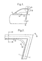
- Figure 1 shows a vehicle door 10 carrying a window frame 12.
- a pane of window glass 14 is slidable in a vertical direction in the window frame 12 and can be raised from and lowered into the lower part of the door 10.
- the window frame 12 is produced from metal or other stiff material and is formed to produce a sharp corner 16.
- the window frame 12 is of channel-shape in cross-section and supports a sealing and guiding strip 18 produced from flexible material such as plastics or rubber and in which the window glass 14 slides.
- the sealing and guiding channel 18 is designed to provide a weather-proof seal for the edge of the window glass and also to impose low friction on the movement of the glass.
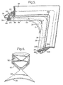
- Figures 2 and 5 show, to an enlarged scale, the window frame 12 and the sealing and guiding channel 18 in the region II of Figure 1.
- the window frame 12 which will be described in more detail with reference to Figures 3 and 4, defines a stiff mounting channel 20 (Fig. 5) in which is supported the sealing and guiding channel 18.
- the channel 18 has a base 22 and side walls 24 and 26. Each of these side walls 24,26 terminates in a respective lip 28,30, the lips having portions 28A and 30A which overlap the respective distal edges of the side walls of the mounting channel 20.
- a third wall 25 extends from the channel base 22 adjacent the side wall 24.
- the wall 25 has a lip 29 which has a portion 29A which abuts (but is not connected to) the lip 28 of the wall 24.
- the lips 29 and 30 also have portions 29B and 30B which extend partway across the mouth of the sealing and guiding channel 18.
- the longitudinal extension of the lip 30 matches the sharp corner 16 of the window frame 12.
- the longitudinal extension of the lip 28 is shaped differently and bridges across the sharp corner 16 in a smooth radius, as indicated over the region A in Figure 5.
- the side wall 24 has to be extended, of course, as indicated at 24A.
- the smooth radius region A is positioned on the inside of the window glass 14.
- the longitudinal extension of the lip 29 bridges across the sharp corner 16 in a smooth radius. This is indicated over region B of Figure 5. It will be seen that the radius B is shorter than radius A and that the smooth curve of the lip 29 follows a path between the smooth curve of the lip 28 and the sharp corner of the lip 30.
- the channel 18 is produced by an extrusion process from plastics or rubber.
- Figure 3 shows a cross-section through the extruded channel 18 at the line III-III of Figure 2.
- Figure 3 also shows the window frame 12 in more detail.
- the window frame 12 comprises channel-shaped metal producing the mounting channel 20, a frame member 36 supporting the channel 20, and an outer trim strip 38.
- the latter is bent to attach it to one of the walls of the mounting channel 20 and to one of the edges (not shown) of the outer frame member 36.
- the latter is bent over the opposite distal edge of the mounting channel 20.
- the window channel 18 defines shoulders 40 and 42 on the outsides of the side walls 24,26 and positioned near the base 22 of the channel. These shoulders 40,42 engage indentations formed in the mounting channel 20 and thus locate the window channel 18 securely in position.
- Figure 3 also shows that the window channel 18 includes a lip 44 at the base of the channel against which the edge of the window glass abuts when the window is fully closed.
- the outwardly facing surface of the lip 44 is covered with flock 46 to provide improved sealing and low friction.
- the lip surfaces 28B and 29B are bent inwardly to allow passage of the window glass.
- the surfaces of the lip portions 28B and 29B which contact the glass are also covered with the flock 46.
- the channel 18 is produced to have the cross-section shown in Figure 3 and a length equal to that from points S and X in Figure 1.
- a cut is made through the side wall 24 of the channel of the position indicated by the line 27 to sever the lip 28 from the remainder of the side wall. This cut starts at the point U in Figure 1 and continues to the point T on the other side of the corner. It will be appreciated that, although the start and end points of this cut are indicated on Figure 1, the cut is in fact made before the channel 18 is mounted on the frame.
- An insert 47 ( Figure 6) is then placed in position as will now be described. This insert produces the required sharp corner in the channel walls 25 and 26 and the lip 30 and the required extended side wall 24A over the region A.
- the insert may be previously moulded and adhesively secured to the channel or may be moulded in situ after the extruded channel has been cut.
- Figure 4 shows a section through the channel 18 at a position after the beginning U of the cut. As shown in Figure 4, the side wall 24 has been cut through and a moulded portion 48 of the insert 47 has been inserted. The moulded portion 48 provides the desired increase in the length of the side wall 24.
- the moulded portion 48 smoothly increases in size towards the corner 16, thus progressively increasing the length of the side wall 24 as shown in Figure 6 and thereby producing the extended side wall portion 24A.
- the moulded portion 48 merges with a channel-shaped moulded portion 50 which is also shown in Figure 4, being a cross-section at the corner 16.
- the side walls 25 and 26 and the lip 30 are cut away to accommodate the channel-shaped portion 50.
- the sealing and guiding channel 18 can be given a sharp radius to match the sharp corner 16 of the frame on the outside of the window and a smooth radius on the inside of the window.
- the portion 48 of the insert 47 may be hidden from view by the lip 29 of the wall 25. This is shown most clearly in Figure 4 where it will be noted that the lip portion 29A is in contact with the side wall 24 approximately at the point where it is secured to the distal edge 49 of the moulded portion 48 of the insert 47.
- the wall 25 completely hides the moulded portion 48 from view. This is advantageous because it means that the sheen and colour of the moulded insert 47 need not match that of the sealing and guiding strip 18.
- the effect of the smooth radius for the lip 29 over the region A means that the lip 29 follows a shorter path than the lips 28 and 30; which follow the sharp corner 16.
- the excess length of the lip 29 is removed by making a cut at 52, removing the excess length and rejoining the ends.
- the cut 52 could be made at any point along the arc A.
Landscapes
- Engineering & Computer Science (AREA)
- Mechanical Engineering (AREA)
- Seal Device For Vehicle (AREA)
- Specific Sealing Or Ventilating Devices For Doors And Windows (AREA)
Claims (16)
- Gorge d'étanchéité et de guidage destinée à une ouverture de fenêtre ayant un angle aigu, comprenant une base de gorge (22) et une première et une deuxième paroi latérale de gorge intégrée (24, 26) constituée d'une matière souple, chaque paroi latérale (24, 26) comportant une lèvre (28, 30) s'étendant le long de son bord distal, la lèvre (26) sur la première paroi latérale (24) étant séparée de cette paroi latérale (24) sur une région s'étendant le long d'une partie de la gorge comprenant l'angle aigu, la lèvre séparée passant de manière régulière par-dessus l'angle aigu, la lèvre (30) sur la deuxième paroi latérale (26) étant séparée de cette paroi latérale au niveau de l'angle et coupée en biais ici pour former un joint à onglet s'adaptant à l'angle aigu, une pièce d'insertion (47, 48) étant fixée entre la lèvre séparée (28) de la première paroi latérale (24) et le restant de cette paroi latérale (24) sur ladite région, caractérisée en ce que la gorge comprend, en outre, une troisième paroi (25) s'étendant à partir de la base de la gorge (22) à côté de la première paroi latérale (24) et constituée d'une matière souple, la troisième paroi (25) comportant une lèvre (29) s'étendant le long de son bord distal qui est séparé de cette paroi latérale (25) au niveau de l'angle et qui suit une courbe régulière entre le joint à onglet de la lèvre de la deuxième paroi latérale (26) et la courbe de la lèvre de la première paroi latérale (28) et qui recouvre ainsi sensiblement ladite pièce d'insertion.
- Gorge selon la revendication 1, caractérisée en ce que la base (22) et au moins des parties des parois (24, 25, 26) sont enlevées au niveau de l'angle aigu et remplacées par des parties correspondantes de ladite pièce d'insertion (47, 48), les parties correspondantes étant fixées en position dans la gorge.
- Gorge selon la revendication 1 ou 2, caractérisée en ce que la lèvre (28) de ladite première paroi latérale (24) est séparée de cette paroi latérale (24) non seulement sur ladite région, mais également jusqu'à une extrémité de la gorge, la lèvre séparée (28) étant re-fixée à la première paroi latérale (24) à l'extérieur de ladite région.
- Gorge selon l'une quelconque des revendications précédentes, caractérisée en ce que la lèvre (29) de la troisième paroi latérale (25) est séparée de cette paroi (25) non seulement sur ladite région, mais également jusqu'à une extrémité de la gorge, la lèvre séparée (29) étant re-fixée à la troisième paroi (25) à l'extérieur de ladite région.
- Gorge selon l'une quelconque des revendications précédentes, caractérisée en ce que la pièce d'insertion (47) est une pièce d'insertion moulée.
- Gorge selon l'une quelconque des revendications précédentes, caractérisée en ce que la pièce d'insertion (47) est fixée à l'aide d'une matière adhésive.
- Gorge selon l'une quelconque des revendications 1 à 5, caractérisée en ce que la pièce d'insertion (47) est fixée par moulage sur la base de la gorge (22) et les parois (24, 25, 26).
- Gorge selon l'une quelconque des revendications précédentes, caractérisée en ce que la base de la gorge (22), les parois latérales (24, 25, 26) et les lèvres (28, 29, 30) sont formées par extrusion.
- Gorge selon l'une quelconque des revendications précédentes, caractérisée en ce que la lèvre (28) est séparée de la première paroi (24) par une découpe à travers la paroi latérale (24) pour séparer sa partie de bord distal comprenant la lèvre (28) du reste de la paroi (24), la découpe s'étendant sur la longueur de la paroi (24) à partir d'une première position d'un côté de l'angle aigu et à travers l'angle aigu.
- Gorge selon la revendication 9, caractérisée en ce que la lèvre (30) est séparée de la deuxième paroi (26) par une découpe à travers la paroi latérale (26) au niveau de l'angle aigu pour séparer une partie de bord distal de celle-ci comprenant la lèvre respective (30) du reste de cette paroi (26), la partie de bord distal de la deuxième paroi (26) étant elle-même découpée au niveau de l'angle aigu pour former dedans ledit joint à onglet.
- Gorge selon la revendication 9 ou 10, caractérisée en ce que la pièce d'insertion (47, 48) a une taille qui, entre ladite première position et l'angle aigu, augmente progressivement l'espacement entre la partie de bord distal de la première paroi (24) et le reste de celle-ci, puis qui diminue progressivement cet espacement jusqu'à zéro dans une seconde position sur le côté opposé de l'angle aigu jusqu'à la première position.
- Gorge selon l'une quelconque des revendications précédentes, caractérisée en ce qu'elle reçoit une vitre de fenêtre pour l'ouverture.
- Gorge selon la revendication 12, caractérisée en ce que la vitre de fenêtre est une vitre de fenêtre coulissante dans un véhicule automobile.
- Gorge selon la revendication 13, caractérisée en ce qu'elle est montée dans un châssis rigide (12, 20) soutenu par la porte du véhicule automobile.
- Gorge selon l'une quelconque des revendications 12 à 14, caractérisée en ce que les lèvres respectives (28, 29) de la première et de la troisième paroi latérale (24, 25) passent partiellement au-dessus de l'ouverture de la gorge pour établir un contact et une étanchéité contre les côtés opposés de la vitre de fenêtre.
- Gorge selon l'une quelconque des revendications 12 à 15, caractérisée par une lèvre (44) à l'intérieur de la gorge et s'étendant obliquement à partir de la base (22) de celle-ci pour venir en prise avec un bord de la vitre de fenêtre.
Applications Claiming Priority (3)
| Application Number | Priority Date | Filing Date | Title |
|---|---|---|---|
| GB9920394 | 1999-08-27 | ||
| GB9920394A GB2353553B (en) | 1999-08-27 | 1999-08-27 | Sealing and guiding strips |
| PCT/GB2000/002975 WO2001015926A1 (fr) | 1999-08-27 | 2000-08-02 | Bande d'etancheite et de guidage destinee a une fenetre |
Publications (2)
| Publication Number | Publication Date |
|---|---|
| EP1206363A1 EP1206363A1 (fr) | 2002-05-22 |
| EP1206363B1 true EP1206363B1 (fr) | 2005-01-05 |
Family
ID=10859983
Family Applications (1)
| Application Number | Title | Priority Date | Filing Date |
|---|---|---|---|
| EP00953277A Expired - Lifetime EP1206363B1 (fr) | 1999-08-27 | 2000-08-02 | Bande d'etancheite et de guidage destinee a une fenetre |
Country Status (10)
| Country | Link |
|---|---|
| US (1) | US6996936B1 (fr) |
| EP (1) | EP1206363B1 (fr) |
| JP (1) | JP2003508288A (fr) |
| CN (1) | CN1137828C (fr) |
| AU (1) | AU6579500A (fr) |
| CZ (1) | CZ2002678A3 (fr) |
| DE (1) | DE60017268T2 (fr) |
| ES (1) | ES2235928T3 (fr) |
| GB (1) | GB2353553B (fr) |
| WO (1) | WO2001015926A1 (fr) |
Families Citing this family (29)
| Publication number | Priority date | Publication date | Assignee | Title |
|---|---|---|---|---|
| GB2372529B (en) * | 2001-02-27 | 2004-08-25 | Gencorp Property Inc | Sealing and guiding strips |
| DE10115124C2 (de) * | 2001-03-27 | 2003-02-20 | Porsche Ag | Sicherungseinrichtung für eine Türscheibe eines Kraftfahrzeugs |
| ITTO20020183A1 (it) * | 2002-03-05 | 2003-09-05 | Metzeler Automotive Profile | Sistema di sigillatura a tenuta per una finestra di un autoveicolo. |
| WO2004050408A1 (fr) * | 2002-12-04 | 2004-06-17 | Gdx North America Inc. | Dispositifs de guidage et d'etancheite pour fenetre |
| DE10347221A1 (de) * | 2003-10-10 | 2005-05-04 | Bayerische Motoren Werke Ag | Dichtungssystem für eine Kraftfahrzeugtür |
| JP4257194B2 (ja) * | 2003-12-10 | 2009-04-22 | 片山工業株式会社 | 車両用ドアサッシュ及びその製造方法 |
| US20060059820A1 (en) * | 2004-08-17 | 2006-03-23 | Intek Plastics, Inc. | Weather seal construction including a weather-strip |
| GB0423875D0 (en) * | 2004-10-27 | 2004-12-01 | Gdx North America Inc | Sealing or guiding assemblies and methods of making them |
| MX2007005963A (es) * | 2004-11-18 | 2007-07-04 | Cooper Standard Automotive Inc | Ensamble de guarnicion interior. |
| GB2425142A (en) * | 2005-04-04 | 2006-10-18 | Gdx North America Inc | Sealing or guiding assemblies and methods of making them |
| US8001728B2 (en) * | 2006-12-27 | 2011-08-23 | Toyoda Gosei Co., Ltd. | Glass run and its attaching structure |
| JP5003384B2 (ja) * | 2007-09-27 | 2012-08-15 | 豊田合成株式会社 | 自動車用ガラスラン |
| JP5034872B2 (ja) * | 2007-10-30 | 2012-09-26 | 豊田合成株式会社 | ガラスラン |
| USD599490S1 (en) * | 2008-07-07 | 2009-09-01 | Endura Products, Inc. | Corner weatherstrip seal |
| US8474189B1 (en) | 2008-10-02 | 2013-07-02 | Intek Plastics, Inc. | Weather strip for use with frame structures having sharp corners |
| EP2454432B1 (fr) * | 2009-07-17 | 2020-03-11 | Cooper-Standard Automotive, Inc. | Profilé en u co-extrudé comportant une coulisse de glace intégrée |
| FR2962087B1 (fr) * | 2010-06-29 | 2012-08-03 | Renault Sa | Dispositif et procede d'etancheite d'une ouverture a cheval sur deux surfaces de carrosserie automobile formant un angle |
| CA2806334A1 (fr) * | 2010-07-28 | 2012-02-02 | Press-Seal Gasket Corporation | Joint d'etancheite de porte de remorque |
| US8661736B2 (en) | 2010-09-09 | 2014-03-04 | GM Global Technology Operations LLC | Vehicle glass run channel |
| JP5339217B2 (ja) * | 2010-09-30 | 2013-11-13 | 豊田合成株式会社 | 自動車用ガラスラン |
| JP5693170B2 (ja) * | 2010-11-18 | 2015-04-01 | 鬼怒川ゴム工業株式会社 | グラスラン |
| FR2972141B1 (fr) * | 2011-03-04 | 2013-03-29 | Peugeot Citroen Automobiles Sa | Joint de coulisse pour vitre mobile de porte de vehicule automobile et porte dont le cadre est equipe d'un tel joint de coulisse |
| US8567130B2 (en) * | 2011-07-13 | 2013-10-29 | John Winston Rhodes | One piece corner fitting |
| US9032668B2 (en) | 2012-09-07 | 2015-05-19 | Press-Seal Gasket Corporation | Seal with primary and secondary sealing lobes for use in roll-up door applications |
| US9649921B2 (en) * | 2013-09-03 | 2017-05-16 | Tokai Kogyo Co., Ltd. | Run channel |
| US9151107B2 (en) | 2013-09-24 | 2015-10-06 | Press-Seal Gasket Corporation | Trailer door seal |
| US9694660B2 (en) * | 2015-06-03 | 2017-07-04 | Nishikawa Rubber Co., Ltd. | Glass run |
| CN105835672B (zh) * | 2016-04-11 | 2017-11-28 | 重庆长安汽车股份有限公司 | 汽车前门上角板与窗框间的密封结构 |
| DE102016117957A1 (de) * | 2016-09-23 | 2018-03-29 | Cooper Standard GmbH | Dichtungsanordnung für ein Kraftfahrzeugfenster, Dichtungsverbund und Verfahren zum Herstellen eines Dichtungsverbundes |
Family Cites Families (17)
| Publication number | Priority date | Publication date | Assignee | Title |
|---|---|---|---|---|
| US5042201A (en) * | 1990-01-18 | 1991-08-27 | The Standard Products Company | One-piece weatherstrip with constant cross-section at corner bends |
| US5010689A (en) * | 1990-03-19 | 1991-04-30 | The Standard Products Company | Glass run channel |
| JPH0813622B2 (ja) * | 1990-04-12 | 1996-02-14 | 豊田合成株式会社 | ウエザストリップの型成形接続方法 |
| JPH0717559Y2 (ja) * | 1990-05-17 | 1995-04-26 | 豊田合成株式会社 | 自動車用ドアガラスラン |
| US5269101A (en) * | 1991-07-29 | 1993-12-14 | Toyoda Gosei Co., Ltd. | Automotive weatherstrip |
| JP2621700B2 (ja) * | 1991-07-29 | 1997-06-18 | 豊田合成株式会社 | 自動車用ウエザストリツプ |
| GB2273951B (en) * | 1992-12-29 | 1996-04-24 | Draftex Ind Ltd | Sealing or guiding strip,window frame assembly,and method of making window frame assembly |
| GB9303678D0 (en) * | 1993-02-24 | 1993-04-14 | Schlegel Uk Holdings | Coloured extruded strips |
| GB2285471B (en) * | 1994-01-11 | 1997-02-12 | Draftex Ind Ltd | Sealing or guiding assemblies and methods of making them |
| US5398451A (en) * | 1994-01-21 | 1995-03-21 | The Standard Products Company | Vehicle glass run channel with corner insert |
| US5493814A (en) * | 1994-04-18 | 1996-02-27 | The Standard Products Company | Weatherstrip assembly including a glass run channel and belt weatherstrip with decorative cover |
| JP3281197B2 (ja) * | 1994-10-28 | 2002-05-13 | 鬼怒川ゴム工業株式会社 | ドアグラスランのコーナー部接合構造 |
| JP2923233B2 (ja) * | 1995-09-19 | 1999-07-26 | 鬼怒川ゴム工業株式会社 | 自動車用ドアグラスランのコーナー部接続構造 |
| GB2311799A (en) * | 1996-04-03 | 1997-10-08 | Draftex Ind Ltd | Sealing and guiding strip for the sharp corner of a vehicle window |
| GB2321268B (en) * | 1997-01-17 | 2000-06-21 | Draftex Ind Ltd | Sealing or guiding assemblies and methods of making them |
| JPH11129836A (ja) * | 1997-10-30 | 1999-05-18 | Kinugawa Rubber Ind Co Ltd | 自動車のサッシュ構造 |
| US6185869B1 (en) * | 1998-05-28 | 2001-02-13 | Katsunori Kawai | Door glass run for a motor vehicle |
-
1999
- 1999-08-27 GB GB9920394A patent/GB2353553B/en not_active Expired - Fee Related
-
2000
- 2000-08-02 AU AU65795/00A patent/AU6579500A/en not_active Abandoned
- 2000-08-02 US US10/069,650 patent/US6996936B1/en not_active Expired - Fee Related
- 2000-08-02 JP JP2001520314A patent/JP2003508288A/ja active Pending
- 2000-08-02 WO PCT/GB2000/002975 patent/WO2001015926A1/fr not_active Ceased
- 2000-08-02 CZ CZ2002678A patent/CZ2002678A3/cs unknown
- 2000-08-02 CN CNB008149453A patent/CN1137828C/zh not_active Expired - Fee Related
- 2000-08-02 EP EP00953277A patent/EP1206363B1/fr not_active Expired - Lifetime
- 2000-08-02 DE DE60017268T patent/DE60017268T2/de not_active Expired - Lifetime
- 2000-08-02 ES ES00953277T patent/ES2235928T3/es not_active Expired - Lifetime
Also Published As
| Publication number | Publication date |
|---|---|
| JP2003508288A (ja) | 2003-03-04 |
| CZ2002678A3 (cs) | 2002-06-12 |
| US6996936B1 (en) | 2006-02-14 |
| DE60017268D1 (de) | 2005-02-10 |
| GB2353553B (en) | 2003-05-21 |
| CN1137828C (zh) | 2004-02-11 |
| GB9920394D0 (en) | 1999-11-03 |
| AU6579500A (en) | 2001-03-26 |
| CN1384789A (zh) | 2002-12-11 |
| ES2235928T3 (es) | 2005-07-16 |
| EP1206363A1 (fr) | 2002-05-22 |
| WO2001015926A1 (fr) | 2001-03-08 |
| GB2353553A (en) | 2001-02-28 |
| DE60017268T2 (de) | 2005-06-02 |
Similar Documents
| Publication | Publication Date | Title |
|---|---|---|
| EP1206363B1 (fr) | Bande d'etancheite et de guidage destinee a une fenetre | |
| EP0788913B1 (fr) | Dispositif d'étanchéité | |
| US6240677B1 (en) | Sealing or guiding assemblies and methods of making them | |
| US5095656A (en) | Integral trim and glass run channel | |
| CN101087702B (zh) | 密封或引导组件及其制作方法 | |
| GB2432870A (en) | Sealing assemblies and methods of making them | |
| US4627145A (en) | Window glass mounting arrangements | |
| GB2327699A (en) | A sealing strip which is longitudinally compressed to match the curves of its aperture before mounting. | |
| EP1567382B1 (fr) | Dispositifs de guidage et d'etancheite pour fenetre | |
| EP0605092B1 (fr) | Joint d'étanchéité ou de guidage, dispositif de châssis de fenêtre et méthode de fabrication | |
| US5163248A (en) | One-piece modular door frame glass run channel | |
| EP0799735A1 (fr) | Joints d'étanchéité et de guidage | |
| US20040134132A1 (en) | Sealing and guiding strips | |
| GB2393751A (en) | Joint in weather strip using both moulding and heat activated material | |
| GB2109042A (en) | Sealing strips | |
| EP1805051B1 (fr) | Ensembles d'etancheite ou de guidage et leur procede de fabrication | |
| US5233758A (en) | Method of making a one-piece modular door frame glass run channel | |
| GB2221238A (en) | Sealing and guiding strip for windows | |
| US4015398A (en) | Channel-shaped sealing, finishing and guiding strips | |
| EP0625446B1 (fr) | Bandes d'étanchéité, de garnissage et de finition | |
| GB2150966A (en) | Window glass sealing or guiding arrangements | |
| EP1881907A1 (fr) | Ensemble d'etancheite ou de guidage et procede d'assemblage correspondant | |
| WO2006106433A9 (fr) | Systèmes d'étanchéification ou de guidage pour fenetres et procédé de montage | |
| JPH0639897A (ja) | ウエザストリップの成形方法 |
Legal Events
| Date | Code | Title | Description |
|---|---|---|---|
| PUAI | Public reference made under article 153(3) epc to a published international application that has entered the european phase |
Free format text: ORIGINAL CODE: 0009012 |
|
| 17P | Request for examination filed |
Effective date: 20020226 |
|
| AX | Request for extension of the european patent |
Free format text: AL;LT;LV;MK;RO;SI |
|
| 17Q | First examination report despatched |
Effective date: 20040213 |
|
| RBV | Designated contracting states (corrected) |
Designated state(s): DE ES FR IT |
|
| GRAP | Despatch of communication of intention to grant a patent |
Free format text: ORIGINAL CODE: EPIDOSNIGR1 |
|
| GRAS | Grant fee paid |
Free format text: ORIGINAL CODE: EPIDOSNIGR3 |
|
| GRAA | (expected) grant |
Free format text: ORIGINAL CODE: 0009210 |
|
| RAP1 | Party data changed (applicant data changed or rights of an application transferred) |
Owner name: GDX NORTH AMERICA INC. |
|
| AK | Designated contracting states |
Kind code of ref document: B1 Designated state(s): DE ES FR IT |
|
| REG | Reference to a national code |
Ref country code: IE Ref legal event code: FG4D |
|
| REF | Corresponds to: |
Ref document number: 60017268 Country of ref document: DE Date of ref document: 20050210 Kind code of ref document: P |
|
| REG | Reference to a national code |
Ref country code: ES Ref legal event code: FG2A Ref document number: 2235928 Country of ref document: ES Kind code of ref document: T3 |
|
| PLBE | No opposition filed within time limit |
Free format text: ORIGINAL CODE: 0009261 |
|
| STAA | Information on the status of an ep patent application or granted ep patent |
Free format text: STATUS: NO OPPOSITION FILED WITHIN TIME LIMIT |
|
| ET | Fr: translation filed | ||
| 26N | No opposition filed |
Effective date: 20051006 |
|
| PGFP | Annual fee paid to national office [announced via postgrant information from national office to epo] |
Ref country code: FR Payment date: 20060808 Year of fee payment: 7 |
|
| PGFP | Annual fee paid to national office [announced via postgrant information from national office to epo] |
Ref country code: IT Payment date: 20060831 Year of fee payment: 7 |
|
| PGFP | Annual fee paid to national office [announced via postgrant information from national office to epo] |
Ref country code: ES Payment date: 20060921 Year of fee payment: 7 |
|
| REG | Reference to a national code |
Ref country code: FR Ref legal event code: ST Effective date: 20080430 |
|
| PG25 | Lapsed in a contracting state [announced via postgrant information from national office to epo] |
Ref country code: FR Free format text: LAPSE BECAUSE OF NON-PAYMENT OF DUE FEES Effective date: 20070831 |
|
| REG | Reference to a national code |
Ref country code: ES Ref legal event code: FD2A Effective date: 20070803 |
|
| PG25 | Lapsed in a contracting state [announced via postgrant information from national office to epo] |
Ref country code: ES Free format text: LAPSE BECAUSE OF NON-PAYMENT OF DUE FEES Effective date: 20070803 |
|
| PG25 | Lapsed in a contracting state [announced via postgrant information from national office to epo] |
Ref country code: IT Free format text: LAPSE BECAUSE OF NON-PAYMENT OF DUE FEES Effective date: 20070802 |
|
| PGFP | Annual fee paid to national office [announced via postgrant information from national office to epo] |
Ref country code: DE Payment date: 20090827 Year of fee payment: 10 |
|
| REG | Reference to a national code |
Ref country code: DE Ref legal event code: R119 Ref document number: 60017268 Country of ref document: DE Effective date: 20110301 |
|
| PG25 | Lapsed in a contracting state [announced via postgrant information from national office to epo] |
Ref country code: DE Free format text: LAPSE BECAUSE OF NON-PAYMENT OF DUE FEES Effective date: 20110301 |