EP1208948A2 - Dispositif pour emmancher et retirer des paliers ou manchons - Google Patents
Dispositif pour emmancher et retirer des paliers ou manchons Download PDFInfo
- Publication number
- EP1208948A2 EP1208948A2 EP01123486A EP01123486A EP1208948A2 EP 1208948 A2 EP1208948 A2 EP 1208948A2 EP 01123486 A EP01123486 A EP 01123486A EP 01123486 A EP01123486 A EP 01123486A EP 1208948 A2 EP1208948 A2 EP 1208948A2
- Authority
- EP
- European Patent Office
- Prior art keywords
- threaded
- centering
- threaded spindle
- der
- threaded nut
- Prior art date
- Legal status (The legal status is an assumption and is not a legal conclusion. Google has not performed a legal analysis and makes no representation as to the accuracy of the status listed.)
- Granted
Links
Images



Classifications
-
- B—PERFORMING OPERATIONS; TRANSPORTING
- B25—HAND TOOLS; PORTABLE POWER-DRIVEN TOOLS; MANIPULATORS
- B25B—TOOLS OR BENCH DEVICES NOT OTHERWISE PROVIDED FOR, FOR FASTENING, CONNECTING, DISENGAGING, OR HOLDING
- B25B27/00—Hand tools, specially adapted for fitting together or separating parts or objects whether or not involving some deformation, not otherwise provided for
- B25B27/02—Hand tools, specially adapted for fitting together or separating parts or objects whether or not involving some deformation, not otherwise provided for for connecting objects by press fit or detaching same
- B25B27/06—Hand tools, specially adapted for fitting together or separating parts or objects whether or not involving some deformation, not otherwise provided for for connecting objects by press fit or detaching same inserting or withdrawing sleeves or bearing races
- B25B27/062—Hand tools, specially adapted for fitting together or separating parts or objects whether or not involving some deformation, not otherwise provided for for connecting objects by press fit or detaching same inserting or withdrawing sleeves or bearing races using screws
-
- B—PERFORMING OPERATIONS; TRANSPORTING
- B25—HAND TOOLS; PORTABLE POWER-DRIVEN TOOLS; MANIPULATORS
- B25B—TOOLS OR BENCH DEVICES NOT OTHERWISE PROVIDED FOR, FOR FASTENING, CONNECTING, DISENGAGING, OR HOLDING
- B25B27/00—Hand tools, specially adapted for fitting together or separating parts or objects whether or not involving some deformation, not otherwise provided for
- B25B27/02—Hand tools, specially adapted for fitting together or separating parts or objects whether or not involving some deformation, not otherwise provided for for connecting objects by press fit or detaching same
- B25B27/023—Hand tools, specially adapted for fitting together or separating parts or objects whether or not involving some deformation, not otherwise provided for for connecting objects by press fit or detaching same using screws
Definitions
- rolling bearings can be Motor vehicles and especially motor vehicles with MacPherson struts and press in. Furthermore, such tools are also used for pulling in Wheel flange hubs are suitable in these roller bearings.
- a generic Wheel bearing changing tool not limited to these areas of application, but can always be used when parts are made of cylindrical Fits should be deducted or pressed into these fits.
- a device for pressing and pulling with the aforementioned Features are known from DE 37 30 017 C1. Is part of the device a spacer tube open on both ends, referring to one of the two A separate front wall can be placed on the end faces. Through a central hole this end wall is one at one end with a driving hexagon provided threaded spindle inserted. Are from the other end Various thrust washers can be pushed onto the threaded spindle. For axial Moving the thrust washer is a threaded nut, which is on the External thread of the threaded spindle rotates and the thrust washer axially shifts. In addition to an axial pressure surface with which the pressure disc z. B. on the bearing to be assembled or disassembled is on the Thrust washer formed a cylindrical centering lug, the Diameter of the centering approach to the inner diameter of the to be drawn or roller bearing to be pressed.
- a disadvantage of this device is that for different types of vehicles very large number of different pressure plates also available must become. This leads to high purchase costs for the device, furthermore there can easily be confusion of the thrust washers with the result that the tool does not fit for a particular application.
- a greatly simplified tool for pressing in and pulling out bearings or Hubs are known from the utility model G 94 02 203. That in it Tool described consists of only a few items, namely in the Basic version made of a cylindrical spacer tube, the threaded spindle as well as the pressure disc covered with hard rubber on the pressure surface. A disadvantage of this tool is inadequate centering of the thrust washer the component to be pulled or pressed in.
- the invention has for its object to make a device for removing and / or pressing bearings or sleeves more universally applicable.
- a device with the features mentioned at the outset is characterized by a centering sleeve surrounding the threaded spindle, on which a cylindrical seat for receiving the thrust washer and the centering shoulder are formed axially in succession.
- the axial pressure surface with which the axial pressure on z. B. the roller bearing to be pulled or pressed in is therefore located on a different part than the centering approach, the sole purpose of which is to center the pulling or pressing tool in the radial direction. This takes into account the fact that the inner diameters of the components to be drawn or pressed in on the one hand and the front diameters of these components on the other hand are often subject to different standard systems in practice.
- a cylindrical seat is first formed on the centering sleeve, which surrounds the threaded spindle, axially one after the other, which serves to accommodate the thrust washer, and a centering projection formed directly on the centering sleeve, which, when the tool is used, is inserted into the inner bore, for. B. the rolling bearing to be pulled engages with little radial play and this centers the tool.
- the centering sleeve also on the one hand and the threaded nut on the other hand are separate components, and that the Centering sleeve with a smooth through hole on the thread of the Threaded spindle is guided.
- a division of tasks is hereby achieved in which the centering sleeve the seat of the thrust washer and the centering of the Tool is used, whereas the generation of the axial pressure by means of Threaded nut is made with an internal thread on the external thread the threaded spindle is seated.
- the centering sleeve is preferably of identical design at both ends Provide shoulders for receiving one end of the nut. To this way, the centering sleeve can be used by both her and her push the other side onto the threaded spindle.
- the Both ends of the centering sleeve can be designed differently, so either Centering approaches to form different diameters, or different to provide large cylindrical seats to accommodate thrust washers. in the Everybody therefore offers the sense of universal applicability of the tool Centering sleeve two different dimensions. Despite this variability, make the centering sleeve compact, if according to a further embodiment the paragraphs which are used to hold the respective end of the threaded nut are provided, are arranged within the centering lugs.
- the centering sleeve with a radially expanded support collar is provided, on which the thrust washer axially supported.
- This support collar allows a uniform over the circumference and tilt-free transmission of the axial pressure from the centering sleeve to the Pressure washer.
- the support collar can be used on both sizes End faces with support surfaces for optional axial support of one Pressure plate be provided, with each of the two support surfaces the seat for receiving the thrust washer and the Centering attachment connects.
- Another embodiment of the device according to the invention is characterized by a securing element for at least provisional Securing the position of the thrust washer on the seat Practical use of the device for.
- B. an accidental in a car workshop To avoid loosening the parts from each other, which is the handling of the Device according to the invention under the often harsh conditions in one Workshop made considerably easier.
- Is particularly suitable as a securing element an elastically deformable and in a circumferential groove of the centering sleeve arranged ring.
- roller bearings 1 and Figures 4 to 6 around a wheel flange hub 2.
- the roller bearing 1 is composed of an outer ring 1a, two inner rings 1b and the rolling elements 1c together.
- the rolling bearing 1 sits in a bearing housing 3, which is part of the wheel suspension Motor vehicle is.
- the installed rolling bearing 1 is via circlips 4a, 4b axially secured within the bearing housing 3.
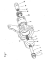
- the tool according to the invention has a basic component continuous threaded spindle 5, at one end with a flats provided hexagon 6 is integrally formed. Below the hexagon 6 is also integrally formed a stop shoulder 7, which at Embodiment supported on the outer ring of a thrust bearing 8. The inner ring of the Axial bearing 8 in turn is supported on the outside 9a of an end wall 9 which Is part of a bell-shaped support element 10.
- the Support element 10 consists of a provided with openings 11 cylindrical part 12, as well as the end wall 9 formed thereon, whereby overall the shape of a bell results, with its open face can support the bearing housing 3.
- the hexagon 6 with the stop shoulder 7 opposite end is a threaded nut 13 on the threaded spindle 5 screwed.
- an internal thread 14 of the threaded nut 13 engages in the External thread 15 of the threaded spindle 5.
- the threaded nut 13 is with a preferably integrally formed thereon hexagon 16. To this It is possible by a relative actuation of the two hexagons 6, 16 to move the threaded nut 13 axially along the threaded spindle 5 and on this way to pull or press the rolling bearing 1 or Apply the required axial pressure to the wheel flange hub 2.
- FIG. 1 shows that the internal thread 14 of the Threaded nut 13 extends only over part of the total length, wherein this threaded section with respect to the center of the total length of the Threaded nut 13 is arranged asymmetrically.
- FIG. 1 is the threaded nut 13 so placed on the threaded spindle 5 that the bearing internal thread 14 is located on the outside, whereas the threaded nut the application of FIG. 3 is placed on the threaded spindle that the load-bearing internal thread 14 is located inside.
- This design of the threaded nut 13 and the internal thread 14 located therein leads to the lowest possible Length of the threaded spindle 5 and thus to a comparatively compact Construction of the tool.
- both ends 17a, 17b of the threaded nut 13 are of the same design, i.e. H. they have the same diameter d.
- Part of the tool is also a centering sleeve 18 coaxially surrounding the threaded spindle 5 smooth surface through bore 19 on the external thread 15 of the Threaded spindle 5 guided centered without engaging with the external thread stand.
- the centering sleeve 18 has centering projections 20a, 20b on. Inward of the centering lugs 20a, 20b is on the centering sleeve 18, respectively a cylindrical seat 21a, 21b is formed for receiving a thrust washer 22.
- the centering sleeve 18 is in the center with a radially expanded support collar 23 Mistake.
- the seat 21a is located between the support collar 23 and the outer centering projection 20a
- the seat 21b is located between the support collar 23 and the centering shoulder, which is also external 20b.
- the centering projection 20a preferably has one at one end of the centering sleeve different outer diameter than the centering projection 20b at the other end of the Centering. In this way, one and the same centering sleeve can be used whether this from their one side or from their other side on the Threaded spindle is placed for centering in the inner rings 1b of two use bearings of different sizes.
- the outer is supported here Shell surface of the centering lugs 20a and 20b on the respective inner bore of the inner ring 1b of the respective rolling bearing 1 from almost without play, which the Tool relating to the rolling bearing to be pulled or pressed in 1 is clearly centered. Due to the small radial play between the Bearing inner diameter and the outer diameter of the centering projection 20a or 20b of the centering sleeve is an optimal alignment of the tool in Given with regard to the rolling bearing to be pulled or pressed.
- Thrust washer 22 represents that element which on the or to be pulled component to be pressed directly exerts the corresponding axial pressure.
- the thrust washer 22 is supported axially on the respectively assigned end face of the radially expanded support collar 23.
- the Support collar 23 is on both ends with support surfaces 25 for optional axial Support the thrust washer 22 provided. 2 is that shown therein Thrust washer 22 with a step-shaped in relation to the axial pressure surface 26 recessed recess 27 provided. This way when pulling or pressing in the rolling bearing 1 while maintaining the axial distance y a pressure of the thrust washer 22 only on the outer ring 1a of the rolling bearing 1 exercised what the disassembly or assembly of the rolling bearing 1 considerably facilitated.
- Tool not only a single centering sleeve 18 and a single one Thrust washer 22. Rather, the user in the automotive workshop various centering sleeves 18 and various pressure plates 22 for Depending on the vehicle make, the centering sleeve / thrust washer combination is available with the correct outside diameter of the centering shoulder and the correctly designed pressure surface and the correct diameter of the pressure plate 22 to put together.
- the number of available Centering sleeves 18 reduced to half, since each centering sleeve 18 has two ends different centering approaches 20a, 20b.
- the diameter of the seat 21a, 21b for everyone to choose from standing centering sleeves 18 is uniform. This allows the Thrust washers 22 with uniform and thus universal inner diameters finished.
- each seat 21a, 21b has a circumferential groove with an elastic therein deformable ring 28, when the thrust washer 22 is pushed on, this ring becomes 28 deformed so that a frictional engagement between centering sleeve 18 and thrust washer 22 arises, which prevents accidental falling of the pressure plate 22. Only against a certain resistance can the thrust washer 22 again Pull off the respective side of the centering sleeve 18.
- Figures 4 and 6 show the retraction of the in two process stages Edge flange hub 2 in the already mounted rolling bearing 1.
- Two are thereby Additional discs 29, 30 for use.
- the additional disc 29 is supported on the one hand on the stop shoulder 7 or the axial bearing 8, and on the other hand on an outer end face of the wheel flange hub 2
- Additional disk 29 is an equivalent to the bell-shaped support element 10 according to Figures 1 and 3.
- the additional disc 30 comes only in the second Process stage according to FIG. 6 for use.
- the additional disk 30 is supported here on the one hand on the inner ring 1b of the rolling bearing 1, and on the other hand on the Front of the centering sleeve 18.
- FIG. 8 shows a modified embodiment of the tool, wherein changes to the area of the stop shoulder 7 of the threaded spindle 5 limit.
- the tool 8 allows some compensation for angular deviations between support element 10 and threaded spindle 5. Cause of such Angular deviation can result in uneven machining of the outer end face of the bearing housing 3.
Landscapes
- Engineering & Computer Science (AREA)
- Mechanical Engineering (AREA)
- Rolling Contact Bearings (AREA)
- Mounting Of Bearings Or Others (AREA)
- Processing Of Meat And Fish (AREA)
- Automatic Assembly (AREA)
Applications Claiming Priority (2)
| Application Number | Priority Date | Filing Date | Title |
|---|---|---|---|
| DE20019617U DE20019617U1 (de) | 2000-11-18 | 2000-11-18 | Vorrichtung zum Abziehen und/oder Einpressen von Lagern oder Hülsen |
| DE20019617U | 2000-11-18 |
Publications (3)
| Publication Number | Publication Date |
|---|---|
| EP1208948A2 true EP1208948A2 (fr) | 2002-05-29 |
| EP1208948A3 EP1208948A3 (fr) | 2006-05-17 |
| EP1208948B1 EP1208948B1 (fr) | 2008-02-20 |
Family
ID=7949000
Family Applications (1)
| Application Number | Title | Priority Date | Filing Date |
|---|---|---|---|
| EP01123486A Expired - Lifetime EP1208948B1 (fr) | 2000-11-18 | 2001-09-28 | Dispositif pour emmancher et retirer des paliers ou manchons |
Country Status (4)
| Country | Link |
|---|---|
| EP (1) | EP1208948B1 (fr) |
| AT (1) | ATE386614T1 (fr) |
| DE (2) | DE20019617U1 (fr) |
| ES (1) | ES2299456T3 (fr) |
Cited By (3)
| Publication number | Priority date | Publication date | Assignee | Title |
|---|---|---|---|---|
| DE202012105052U1 (de) | 2011-12-23 | 2013-01-25 | Shou King Enterprise Co., Ltd | Werkzeugsatz zum Abziehen und/oder Einpressen von Wälzlagern |
| US9956674B2 (en) | 2016-01-26 | 2018-05-01 | Ford Global Technologies, Llc | Replacement tool for driveshaft yoke bushings |
| CN117359537A (zh) * | 2022-06-30 | 2024-01-09 | 联芯集成电路制造(厦门)有限公司 | 一种用于更换轴承的夹具以及更换轴承的方法 |
Families Citing this family (2)
| Publication number | Priority date | Publication date | Assignee | Title |
|---|---|---|---|---|
| DE202005006802U1 (de) * | 2005-04-28 | 2005-07-21 | Klann-Spezial-Werkzeugbau-Gmbh | Vorrichtung mit einer Zugspindel zum Einziehen eines Radlagers |
| CN107803784A (zh) * | 2017-11-02 | 2018-03-16 | 中车株洲电机有限公司 | 一种卧式压装轴承方法和圆柱轴承内圈拆卸方法及装置 |
Family Cites Families (7)
| Publication number | Priority date | Publication date | Assignee | Title |
|---|---|---|---|---|
| US2068021A (en) * | 1935-08-07 | 1937-01-19 | Myron A Hamman | Bushing extracting and inserting tool |
| US2573567A (en) * | 1949-06-11 | 1951-10-30 | William L Ruhle | Pump and ram hydraulic lifting device |
| US4476617A (en) * | 1982-07-02 | 1984-10-16 | The Spencer Turbine Company | Bearing installation tool |
| DE3443249C2 (de) * | 1984-11-23 | 1986-12-18 | Franc 1000 Berlin Kroselj | Werkzeugsatz zum Aus- oder Einbauen von Wälzlagern |
| DE3730017C1 (de) * | 1987-09-08 | 1989-01-26 | Horst Klann | Vorrichtung zum Einpressen und Abziehen von Lagern oder Huelsen,insbesondere fuer Achslager und/oder Radflanschnaben an Kraftfahrzeugen |
| US5165169A (en) * | 1991-10-31 | 1992-11-24 | The United States Of America As Represented By The Administrator Of The National Aeronautics And Space Administration | Bearing servicing tool |
| DE9402203U1 (de) * | 1994-02-10 | 1994-03-31 | Bechtold, Ralf, 79211 Denzlingen | Vorrichtung zum Einpressen und Abziehen von Lagern oder Naben oder ähnlichen Teilen, insbesondere für Radlager oder Radflanschnaben an Kraftfahrzeugen |
-
2000
- 2000-11-18 DE DE20019617U patent/DE20019617U1/de not_active Expired - Lifetime
-
2001
- 2001-09-28 EP EP01123486A patent/EP1208948B1/fr not_active Expired - Lifetime
- 2001-09-28 ES ES01123486T patent/ES2299456T3/es not_active Expired - Lifetime
- 2001-09-28 DE DE50113623T patent/DE50113623D1/de not_active Expired - Lifetime
- 2001-09-28 AT AT01123486T patent/ATE386614T1/de active
Cited By (3)
| Publication number | Priority date | Publication date | Assignee | Title |
|---|---|---|---|---|
| DE202012105052U1 (de) | 2011-12-23 | 2013-01-25 | Shou King Enterprise Co., Ltd | Werkzeugsatz zum Abziehen und/oder Einpressen von Wälzlagern |
| US9956674B2 (en) | 2016-01-26 | 2018-05-01 | Ford Global Technologies, Llc | Replacement tool for driveshaft yoke bushings |
| CN117359537A (zh) * | 2022-06-30 | 2024-01-09 | 联芯集成电路制造(厦门)有限公司 | 一种用于更换轴承的夹具以及更换轴承的方法 |
Also Published As
| Publication number | Publication date |
|---|---|
| EP1208948A3 (fr) | 2006-05-17 |
| ES2299456T3 (es) | 2008-06-01 |
| DE20019617U1 (de) | 2001-01-18 |
| DE50113623D1 (de) | 2008-04-03 |
| EP1208948B1 (fr) | 2008-02-20 |
| ATE386614T1 (de) | 2008-03-15 |
Similar Documents
| Publication | Publication Date | Title |
|---|---|---|
| DE69224457T2 (de) | Federmontage, insbesondere für automatisches Getriebe eines Fahrzeugs | |
| DE19713211C2 (de) | Lagervorrichtung für eine Achse | |
| EP0306738B1 (fr) | Dispositif pour emmancher et retirer des paliers ou manchons, surtout pour paliers d'arbre et/ou moyeux de boudin de roue de véhicules à moteur | |
| EP2236248B1 (fr) | Dispositif de démontage d'un boîtier de palier à roulement | |
| DE3443249C2 (de) | Werkzeugsatz zum Aus- oder Einbauen von Wälzlagern | |
| DE602004010630T2 (de) | Verfahren zur montage einer wälzlagervorrichtung | |
| EP0921328A2 (fr) | Douille avec une collerette médiane, son utilisation et son procédé de fabrication | |
| DE102007014479B4 (de) | Spannvorrichtung | |
| DE10050777B4 (de) | Luftfeder und Verfahren zur Herstellung einer Luftfeder | |
| DE69618149T2 (de) | Schutzflansch für Rollenlager, damit ausgerüstetes Lager und Herstellungsverfahren für einen Lagerring, der mit einem Schutzflansch versehen ist | |
| DE2810028A1 (de) | Kombiniertes axial-radiallager | |
| EP1790437B1 (fr) | Méthode pour monter en force un moyeu de roue muni d'un palier de roue | |
| EP1503096B1 (fr) | Organe de retenue pour la fixation d'au moins un palier | |
| DE112008002217T5 (de) | Differential mit Ausgleichsbolzen-Haltesystem und Verfahren zum Zusammenbau | |
| EP1208948B1 (fr) | Dispositif pour emmancher et retirer des paliers ou manchons | |
| DE2543211C2 (de) | Lenkrolle für von Hand bewegte Fahrzeuge insbesondere für Einkaufswagen | |
| EP0475088B1 (fr) | Palier pour essieux de roues de remorque | |
| DE10033894A1 (de) | Demontagevorrichtung für ein selbsteinstellendes Lager | |
| EP1328735A1 (fr) | Dispositif de fixation | |
| EP0565773B1 (fr) | Dispositif de fixation rapide avec centrage central pour le montage d'une roue de véhicule sur l'axe d'une machine d'équilibrage | |
| EP0776775A1 (fr) | Palier de roue | |
| DE9012194U1 (de) | Werkzeug zum Ausbauen und Einbauen von Lagern | |
| EP3433517B1 (fr) | Dispositif d'étanchéité pour l'étanchéification de l'articulation à rotule d'un pivot de fusée | |
| EP4157682B1 (fr) | Disposition de moyeu de roue et anneau de pole pour un capteur abs | |
| DD248323A1 (de) | Einbau von paarweise angeordneten, zweigeteilten lagern, insbesondere kegelrollenlagern |
Legal Events
| Date | Code | Title | Description |
|---|---|---|---|
| PUAI | Public reference made under article 153(3) epc to a published international application that has entered the european phase |
Free format text: ORIGINAL CODE: 0009012 |
|
| AK | Designated contracting states |
Kind code of ref document: A2 Designated state(s): AT BE CH CY DE DK ES FI FR GB GR IE IT LI LU MC NL PT SE TR |
|
| AX | Request for extension of the european patent |
Free format text: AL;LT;LV;MK;RO;SI |
|
| PUAL | Search report despatched |
Free format text: ORIGINAL CODE: 0009013 |
|
| AK | Designated contracting states |
Kind code of ref document: A3 Designated state(s): AT BE CH CY DE DK ES FI FR GB GR IE IT LI LU MC NL PT SE TR |
|
| AX | Request for extension of the european patent |
Extension state: AL LT LV MK RO SI |
|
| 17P | Request for examination filed |
Effective date: 20060411 |
|
| 17Q | First examination report despatched |
Effective date: 20060809 |
|
| AKX | Designation fees paid |
Designated state(s): AT BE CH CY DE DK ES FI FR GB GR IE IT LI LU MC NL PT SE TR |
|
| GRAP | Despatch of communication of intention to grant a patent |
Free format text: ORIGINAL CODE: EPIDOSNIGR1 |
|
| GRAS | Grant fee paid |
Free format text: ORIGINAL CODE: EPIDOSNIGR3 |
|
| GRAA | (expected) grant |
Free format text: ORIGINAL CODE: 0009210 |
|
| AK | Designated contracting states |
Kind code of ref document: B1 Designated state(s): AT BE CH CY DE DK ES FI FR GB GR IE IT LI LU MC NL PT SE TR |
|
| REG | Reference to a national code |
Ref country code: GB Ref legal event code: FG4D Free format text: NOT ENGLISH |
|
| REG | Reference to a national code |
Ref country code: CH Ref legal event code: EP |
|
| REG | Reference to a national code |
Ref country code: IE Ref legal event code: FG4D Free format text: LANGUAGE OF EP DOCUMENT: GERMAN |
|
| REF | Corresponds to: |
Ref document number: 50113623 Country of ref document: DE Date of ref document: 20080403 Kind code of ref document: P |
|
| REG | Reference to a national code |
Ref country code: ES Ref legal event code: FG2A Ref document number: 2299456 Country of ref document: ES Kind code of ref document: T3 |
|
| PG25 | Lapsed in a contracting state [announced via postgrant information from national office to epo] |
Ref country code: FI Free format text: LAPSE BECAUSE OF FAILURE TO SUBMIT A TRANSLATION OF THE DESCRIPTION OR TO PAY THE FEE WITHIN THE PRESCRIBED TIME-LIMIT Effective date: 20080220 |
|
| ET | Fr: translation filed | ||
| REG | Reference to a national code |
Ref country code: IE Ref legal event code: FD4D |
|
| PG25 | Lapsed in a contracting state [announced via postgrant information from national office to epo] |
Ref country code: SE Free format text: LAPSE BECAUSE OF FAILURE TO SUBMIT A TRANSLATION OF THE DESCRIPTION OR TO PAY THE FEE WITHIN THE PRESCRIBED TIME-LIMIT Effective date: 20080520 Ref country code: PT Free format text: LAPSE BECAUSE OF FAILURE TO SUBMIT A TRANSLATION OF THE DESCRIPTION OR TO PAY THE FEE WITHIN THE PRESCRIBED TIME-LIMIT Effective date: 20080721 Ref country code: DK Free format text: LAPSE BECAUSE OF FAILURE TO SUBMIT A TRANSLATION OF THE DESCRIPTION OR TO PAY THE FEE WITHIN THE PRESCRIBED TIME-LIMIT Effective date: 20080220 Ref country code: IE Free format text: LAPSE BECAUSE OF FAILURE TO SUBMIT A TRANSLATION OF THE DESCRIPTION OR TO PAY THE FEE WITHIN THE PRESCRIBED TIME-LIMIT Effective date: 20080220 |
|
| PLBE | No opposition filed within time limit |
Free format text: ORIGINAL CODE: 0009261 |
|
| STAA | Information on the status of an ep patent application or granted ep patent |
Free format text: STATUS: NO OPPOSITION FILED WITHIN TIME LIMIT |
|
| 26N | No opposition filed |
Effective date: 20081121 |
|
| PG25 | Lapsed in a contracting state [announced via postgrant information from national office to epo] |
Ref country code: MC Free format text: LAPSE BECAUSE OF NON-PAYMENT OF DUE FEES Effective date: 20080930 |
|
| REG | Reference to a national code |
Ref country code: CH Ref legal event code: PL |
|
| PG25 | Lapsed in a contracting state [announced via postgrant information from national office to epo] |
Ref country code: CY Free format text: LAPSE BECAUSE OF FAILURE TO SUBMIT A TRANSLATION OF THE DESCRIPTION OR TO PAY THE FEE WITHIN THE PRESCRIBED TIME-LIMIT Effective date: 20080220 |
|
| PG25 | Lapsed in a contracting state [announced via postgrant information from national office to epo] |
Ref country code: CH Free format text: LAPSE BECAUSE OF NON-PAYMENT OF DUE FEES Effective date: 20080930 Ref country code: LI Free format text: LAPSE BECAUSE OF NON-PAYMENT OF DUE FEES Effective date: 20080930 |
|
| PG25 | Lapsed in a contracting state [announced via postgrant information from national office to epo] |
Ref country code: LU Free format text: LAPSE BECAUSE OF NON-PAYMENT OF DUE FEES Effective date: 20080928 |
|
| PG25 | Lapsed in a contracting state [announced via postgrant information from national office to epo] |
Ref country code: TR Free format text: LAPSE BECAUSE OF FAILURE TO SUBMIT A TRANSLATION OF THE DESCRIPTION OR TO PAY THE FEE WITHIN THE PRESCRIBED TIME-LIMIT Effective date: 20080220 |
|
| PG25 | Lapsed in a contracting state [announced via postgrant information from national office to epo] |
Ref country code: GR Free format text: LAPSE BECAUSE OF FAILURE TO SUBMIT A TRANSLATION OF THE DESCRIPTION OR TO PAY THE FEE WITHIN THE PRESCRIBED TIME-LIMIT Effective date: 20080521 |
|
| PGFP | Annual fee paid to national office [announced via postgrant information from national office to epo] |
Ref country code: FR Payment date: 20140919 Year of fee payment: 14 Ref country code: GB Payment date: 20140919 Year of fee payment: 14 Ref country code: ES Payment date: 20140926 Year of fee payment: 14 Ref country code: AT Payment date: 20140630 Year of fee payment: 14 |
|
| PGFP | Annual fee paid to national office [announced via postgrant information from national office to epo] |
Ref country code: NL Payment date: 20140918 Year of fee payment: 14 |
|
| PGFP | Annual fee paid to national office [announced via postgrant information from national office to epo] |
Ref country code: IT Payment date: 20140929 Year of fee payment: 14 |
|
| PGFP | Annual fee paid to national office [announced via postgrant information from national office to epo] |
Ref country code: BE Payment date: 20140919 Year of fee payment: 14 |
|
| PG25 | Lapsed in a contracting state [announced via postgrant information from national office to epo] |
Ref country code: IT Free format text: LAPSE BECAUSE OF NON-PAYMENT OF DUE FEES Effective date: 20150928 |
|
| REG | Reference to a national code |
Ref country code: AT Ref legal event code: MM01 Ref document number: 386614 Country of ref document: AT Kind code of ref document: T Effective date: 20150928 |
|
| GBPC | Gb: european patent ceased through non-payment of renewal fee |
Effective date: 20150928 |
|
| REG | Reference to a national code |
Ref country code: NL Ref legal event code: MM Effective date: 20151001 |
|
| REG | Reference to a national code |
Ref country code: FR Ref legal event code: ST Effective date: 20160531 |
|
| PG25 | Lapsed in a contracting state [announced via postgrant information from national office to epo] |
Ref country code: GB Free format text: LAPSE BECAUSE OF NON-PAYMENT OF DUE FEES Effective date: 20150928 |
|
| PG25 | Lapsed in a contracting state [announced via postgrant information from national office to epo] |
Ref country code: FR Free format text: LAPSE BECAUSE OF NON-PAYMENT OF DUE FEES Effective date: 20150930 Ref country code: AT Free format text: LAPSE BECAUSE OF NON-PAYMENT OF DUE FEES Effective date: 20150928 Ref country code: NL Free format text: LAPSE BECAUSE OF NON-PAYMENT OF DUE FEES Effective date: 20151001 |
|
| REG | Reference to a national code |
Ref country code: ES Ref legal event code: FD2A Effective date: 20161026 |
|
| PG25 | Lapsed in a contracting state [announced via postgrant information from national office to epo] |
Ref country code: ES Free format text: LAPSE BECAUSE OF NON-PAYMENT OF DUE FEES Effective date: 20150929 |
|
| PG25 | Lapsed in a contracting state [announced via postgrant information from national office to epo] |
Ref country code: BE Free format text: LAPSE BECAUSE OF NON-PAYMENT OF DUE FEES Effective date: 20150930 |
|
| PGFP | Annual fee paid to national office [announced via postgrant information from national office to epo] |
Ref country code: DE Payment date: 20170928 Year of fee payment: 17 |
|
| REG | Reference to a national code |
Ref country code: DE Ref legal event code: R119 Ref document number: 50113623 Country of ref document: DE |
|
| PG25 | Lapsed in a contracting state [announced via postgrant information from national office to epo] |
Ref country code: DE Free format text: LAPSE BECAUSE OF NON-PAYMENT OF DUE FEES Effective date: 20190402 |