EP1216971A1 - Procede de fabrication de vitrage sous vide et systeme mecanique d'application - Google Patents
Procede de fabrication de vitrage sous vide et systeme mecanique d'application Download PDFInfo
- Publication number
- EP1216971A1 EP1216971A1 EP99939904A EP99939904A EP1216971A1 EP 1216971 A1 EP1216971 A1 EP 1216971A1 EP 99939904 A EP99939904 A EP 99939904A EP 99939904 A EP99939904 A EP 99939904A EP 1216971 A1 EP1216971 A1 EP 1216971A1
- Authority
- EP
- European Patent Office
- Prior art keywords
- glass
- sealing
- chamber
- vacuum
- hole
- Prior art date
- Legal status (The legal status is an assumption and is not a legal conclusion. Google has not performed a legal analysis and makes no representation as to the accuracy of the status listed.)
- Withdrawn
Links
- 238000000034 method Methods 0.000 title claims abstract description 74
- 238000004519 manufacturing process Methods 0.000 title claims abstract description 71
- 239000011521 glass Substances 0.000 claims abstract description 195
- 238000007789 sealing Methods 0.000 claims abstract description 119
- 238000010438 heat treatment Methods 0.000 claims abstract description 54
- 239000005394 sealing glass Substances 0.000 claims abstract description 53
- 238000001816 cooling Methods 0.000 claims description 28
- 238000002844 melting Methods 0.000 claims description 23
- 230000008018 melting Effects 0.000 claims description 23
- 239000000843 powder Substances 0.000 claims description 22
- 238000003795 desorption Methods 0.000 claims description 4
- 230000005855 radiation Effects 0.000 claims description 4
- 239000000126 substance Substances 0.000 claims description 3
- 238000009423 ventilation Methods 0.000 claims 3
- 230000005611 electricity Effects 0.000 claims 2
- 230000000149 penetrating effect Effects 0.000 claims 1
- 238000005086 pumping Methods 0.000 abstract description 8
- 230000008901 benefit Effects 0.000 abstract description 6
- 239000002184 metal Substances 0.000 abstract description 4
- 238000010521 absorption reaction Methods 0.000 abstract 1
- 230000008569 process Effects 0.000 description 6
- 230000007246 mechanism Effects 0.000 description 4
- WWSJZGAPAVMETJ-UHFFFAOYSA-N 2-[4-[2-(2,3-dihydro-1H-inden-2-ylamino)pyrimidin-5-yl]-3-ethoxypyrazol-1-yl]-1-(2,4,6,7-tetrahydrotriazolo[4,5-c]pyridin-5-yl)ethanone Chemical compound C1C(CC2=CC=CC=C12)NC1=NC=C(C=N1)C=1C(=NN(C=1)CC(=O)N1CC2=C(CC1)NN=N2)OCC WWSJZGAPAVMETJ-UHFFFAOYSA-N 0.000 description 3
- 230000000694 effects Effects 0.000 description 3
- 230000035939 shock Effects 0.000 description 2
- VYPSYNLAJGMNEJ-UHFFFAOYSA-N Silicium dioxide Chemical compound O=[Si]=O VYPSYNLAJGMNEJ-UHFFFAOYSA-N 0.000 description 1
- 239000000956 alloy Substances 0.000 description 1
- 229910045601 alloy Inorganic materials 0.000 description 1
- 230000009286 beneficial effect Effects 0.000 description 1
- 239000000919 ceramic Substances 0.000 description 1
- 230000008859 change Effects 0.000 description 1
- 238000010276 construction Methods 0.000 description 1
- 230000003247 decreasing effect Effects 0.000 description 1
- 238000005265 energy consumption Methods 0.000 description 1
- 239000005329 float glass Substances 0.000 description 1
- 238000009413 insulation Methods 0.000 description 1
- 239000012212 insulator Substances 0.000 description 1
- 238000004093 laser heating Methods 0.000 description 1
- 230000004048 modification Effects 0.000 description 1
- 238000012986 modification Methods 0.000 description 1
- 230000002093 peripheral effect Effects 0.000 description 1
- 230000009467 reduction Effects 0.000 description 1
- 238000001179 sorption measurement Methods 0.000 description 1
Images


Classifications
-
- E—FIXED CONSTRUCTIONS
- E06—DOORS, WINDOWS, SHUTTERS, OR ROLLER BLINDS IN GENERAL; LADDERS
- E06B—FIXED OR MOVABLE CLOSURES FOR OPENINGS IN BUILDINGS, VEHICLES, FENCES OR LIKE ENCLOSURES IN GENERAL, e.g. DOORS, WINDOWS, BLINDS, GATES
- E06B3/00—Window sashes, door leaves, or like elements for closing wall or like openings; Layout of fixed or moving closures, e.g. windows in wall or like openings; Features of rigidly-mounted outer frames relating to the mounting of wing frames
- E06B3/66—Units comprising two or more parallel glass or like panes permanently secured together
- E06B3/6612—Evacuated glazing units
-
- C—CHEMISTRY; METALLURGY
- C03—GLASS; MINERAL OR SLAG WOOL
- C03C—CHEMICAL COMPOSITION OF GLASSES, GLAZES OR VITREOUS ENAMELS; SURFACE TREATMENT OF GLASS; SURFACE TREATMENT OF FIBRES OR FILAMENTS MADE FROM GLASS, MINERALS OR SLAGS; JOINING GLASS TO GLASS OR OTHER MATERIALS
- C03C27/00—Joining pieces of glass to pieces of other inorganic material; Joining glass to glass other than by fusing
- C03C27/06—Joining glass to glass by processes other than fusing
-
- E—FIXED CONSTRUCTIONS
- E06—DOORS, WINDOWS, SHUTTERS, OR ROLLER BLINDS IN GENERAL; LADDERS
- E06B—FIXED OR MOVABLE CLOSURES FOR OPENINGS IN BUILDINGS, VEHICLES, FENCES OR LIKE ENCLOSURES IN GENERAL, e.g. DOORS, WINDOWS, BLINDS, GATES
- E06B3/00—Window sashes, door leaves, or like elements for closing wall or like openings; Layout of fixed or moving closures, e.g. windows in wall or like openings; Features of rigidly-mounted outer frames relating to the mounting of wing frames
- E06B3/66—Units comprising two or more parallel glass or like panes permanently secured together
- E06B3/677—Evacuating or filling the gap between the panes ; Equilibration of inside and outside pressure; Preventing condensation in the gap between the panes; Cleaning the gap between the panes
- E06B3/6775—Evacuating or filling the gap during assembly
-
- Y—GENERAL TAGGING OF NEW TECHNOLOGICAL DEVELOPMENTS; GENERAL TAGGING OF CROSS-SECTIONAL TECHNOLOGIES SPANNING OVER SEVERAL SECTIONS OF THE IPC; TECHNICAL SUBJECTS COVERED BY FORMER USPC CROSS-REFERENCE ART COLLECTIONS [XRACs] AND DIGESTS
- Y02—TECHNOLOGIES OR APPLICATIONS FOR MITIGATION OR ADAPTATION AGAINST CLIMATE CHANGE
- Y02A—TECHNOLOGIES FOR ADAPTATION TO CLIMATE CHANGE
- Y02A30/00—Adapting or protecting infrastructure or their operation
- Y02A30/24—Structural elements or technologies for improving thermal insulation
- Y02A30/249—Glazing, e.g. vacuum glazing
-
- Y—GENERAL TAGGING OF NEW TECHNOLOGICAL DEVELOPMENTS; GENERAL TAGGING OF CROSS-SECTIONAL TECHNOLOGIES SPANNING OVER SEVERAL SECTIONS OF THE IPC; TECHNICAL SUBJECTS COVERED BY FORMER USPC CROSS-REFERENCE ART COLLECTIONS [XRACs] AND DIGESTS
- Y02—TECHNOLOGIES OR APPLICATIONS FOR MITIGATION OR ADAPTATION AGAINST CLIMATE CHANGE
- Y02B—CLIMATE CHANGE MITIGATION TECHNOLOGIES RELATED TO BUILDINGS, e.g. HOUSING, HOUSE APPLIANCES OR RELATED END-USER APPLICATIONS
- Y02B80/00—Architectural or constructional elements improving the thermal performance of buildings
- Y02B80/22—Glazing, e.g. vaccum glazing
Definitions
- the present invention relates to a method for manufacturing vacuum glazing and its application mechanical system.
- Vacuum glazing is a kind of thermal insulator used in construction field such as for doors and windows, etc.
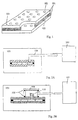
- FIG. 1 A typical structure of vacuum glazing is shown in Fig. 1, in which the numeral 101 designates two pieces of glass sheets, 102 the supports and 103 the sealing glass and 104 the evacuating hole, wherein the space between the two glass sheets is in a vacuum state.
- the vacuity in the space between the two glass sheets has to be reached and maintained at 10 -2 Pa to make the gas heat transfer little enough to be neglected.
- an excellent and stable insulating property is obtained. Therefore, the eligible products can be obtained only by designing a requisite evacuating system according to the required vacuity target when the vacuum glazing is manufactured.
- the process for vacuum-pumping treatment of vacuum glazing is conducted by applying traditional procedure similar to the process for producing thermos, in which evacuating hole of each vacuum glazing is separately connected to a vacuum system by a evacuating pipeline.
- the method is shown in Fig. 2A, in which the long glass evacuating tube 106 of vacuum glazing is extended directly to the outside of the oven 105 and connected to the vacuum system107. The long glass tube is burned to be broken off and sealed after the vacuum glazing is baked and evacuated.
- Another method is shown in Fig. 2B, in which a cup-like component 109 with a gasket ring 108 is put over the evacuating hole on the vacuum glazing reversedly, and connected to the evacuating system 107 by a metal tube.
- the heating coil 110 previously installed in the vacuum cup is powered to make the glass evacuating tube to be melted and sealed after the vacuum glazing is baked and evacuated.
- one difficulty of the method by means of glass tube connection shown in Fig. 2A is that the evacuating hole can not be prepared with a relatively thick glass tube, while the mechanical strength of thin glass tube is so low that the operation with it is not easy; the second difficulty is that a long residue evacuating tube is not permitted to be present for vacuum glazing so that the hole-sealing operation is relatively difficult.
- the method by means of cup-like device shown in Fig. 2B solved the difficulties described above, but the current gasket can only endure a temperature up to 200°C, it cannot be baked at a high temperature more than 300°C. Therefore, the quality and stability of products are degraded due to the insufficient air evacuation of the vacuum glazing.
- the present invention provides a method for manufacturing vacuum glazing so as to manufacture products with high quality, high stability and high reliability with a simpler device, a higher evacuating efficiency and a simpler operation.
- the present invention also provides a device for manufacturing vacuum glazing to make the fabrication of vacuum glazing efficient and energy saving.
- Another aspect of the present invention provides a method for manufacturing vacuum glazing, comprising the following steps:
- a further aspect of the present invention provides a device for manufacturing the vacuum glazing, comprising:
- a still further aspect of the present invention provides a device for manufacturing vacuum glazing, which is used to fabricate vacuum glazing from a starting glass sheet, the said starting glass sheet includes two pieces of glass placed oppositely, there is a space between the two pieces of glass, and a plurality of supports are put in the space to maintain it, wherein at least one of the pieces of glass provides a hole which communicates with the space formed between the two pieces of glass and is used for evacuation.
- the said device comprises:
- the present invention also provides a device for manufacturing a vacuum glazing, which comprises:
- the present invention also provides a device for manufacturing vacuum glazing, which comprises:
- a further aspect of the present invention provides a method for manufacturing vacuum glazing, which comprises the following steps:
- the starting sheet 10 of vacuum glazing includes two oppositely placed pieces of glass 1a, 1b, between which is a space and is put into a plurality of supports 2 to keep the space, wherein at least one of the pieces of glass has a pump out tube which communicates with the space formed between the two pieces of glass and is used for evacuation. It is desirable that the pump out tube locates in the vicinity of the edges or corners of the glass sheet.
- the said pump out tube can be more than one.
- the pieces of glass for manufacturing vacuum glazing can be common pieces of glass, such as float glass, wire glass, coat glass, colored glass, etc.
- the supports can be the common supports such as the supports made of metal, ceramic, alloy and the like.
- the placed starting sheet 10 of vacuum glazing is put into an airtight chamber, e.g. vacuum chamber 5, which has the volume large enough to contain the whole starting sheet of vacuum glazing and communicates with the vacuum system 7 by a large diameter pipeline 6 to make the chamber reach the required vacuity when needed.
- an airtight chamber e.g. vacuum chamber 5
- the sealing glass 3 such as seal glass bars, glass powders, can be used to seal the edges of the starting sheet of vacuum glazing. Molten sealing glass is used and the sealing glass 3 is heated to be melt, to seal the edges of starting sheet of vacuum glazing.
- the edges of the starting sheet of vacuum glazing is sealed by heating the starting sheet 10 of vacuum glazing to melt the sealing glass 3 which previously put on the edges of the starting sheet of vacuum glazing, then cooling to solidify the sealing glass.
- the heating temperature is the melting temperature or above. Since different sealing glasses have different melting temperatures, the heating temperature is usually in the range of about 350°C to about 550°C.
- the starting sheet of vacuum glazing can be heated by electric heater or hot gas heater.
- the sealing glass used can be the conventional sealing glass available commercially.
- the preferred sealing glass of the present invention is the sealing glass powder. There are many kinds of glass powder, the one of which thermal expansion coefficient matches with that of the starting sheet of vacuum glazing is preferable.
- the starting sheet of vacuum glazing should be evacuated to the required vacuity after being sealed on the edges.
- the change of the vacuity of the inner space in the starting sheet of vacuum glazing is achieved by changing the vacuity of the vacuum chamber which contains the starting sheet of vacuum glazing.
- the evacuation step of the present invention can be conducted when the starting sheet 10 of vacuum glazing is at the room temperature or an elevated temperature.
- the evacuation is preferably conducted when the temperature of starting sheet of vacuum glazing is at an elevated temperature from above 150°C to below the melting temperature of the sealing glass used, more preferably when the temperature is at an elevated temperature from about 300°C to the melting temperature of the sealing glass used.
- evacuation temperature the temperature, at which the moisture and the like absorbed on the starting sheet of vacuum glazing can be desorbed, is called evacuation temperature.
- the hole-sealing step starts when the vacuity of the inner space within the starting sheet of vacuum glazing 10 reaches the required vacuity, usually 10 -1 to 10 -4 Pa, that is, to seal the hole on the starting sheet of vacuum glazing, thereby obtaining the vacuum glazing with the required vacuity within its inner space.
- the hole-sealing can be conducted by applying the usual hole-sealing processes.
- the hole-sealing step is achieved by heating and melting the glass tube 4 connected with the evacuating hole. One end of the glass tube 4 is connected with the evacuating hole, and the other is communicated with the environment, e. g. extending out of the outside surface of the glass sheet.
- the part of the glass tube can extend out of the outside surface of the glass sheet as short as possible.
- the heating can be conducted by using, for example, electric heater, or infrared or laser radiation device.
- the evacuating hole of the glass sheet is sealed by utilizing the heating coil 9 put on the evacuating hole previously so that the eligible vacuum glazing can be obtained.
- Fig 3B is substantially the same as Fig.
- a window 9' which can be penetrated by infrared or laser ray, such as quartz glass window 9', and the purpose of hole-sealing can be achieved by utilizing the outside infrared spotlight or laser 9" to heat the evacuating tube 4 on the evacuating hole when the condition of hole-sealing is reached.
- the purpose of hole-sealing can also be achieved by using the infrared spotlight or laser (not shown) within the vacuum chamber 5 to heat the evacuating tube.
- the glass tube can be ordinary glass tubes or glass tubes which absorb infrared light, wherein the glass tubes absorbing infrared light is prefered.
- the glass tube 4 described above connects with the evacuating hole.
- the glass tube is put on the evacuating hole and the sealing glass, for example a sealing glass lantern ring pressed previously, is arranged at its joint part with the evacuating hole, then making the glass tube connect with the evacuating hole by heating and melting the sealing glass.
- This heating and melting step is preferably conducted together with the step of sealing the edges of the starting sheet 10 of vacuum glazing simultaneously.
- the vacuum glazing after being evacuated and sealed need to be cooled.
- the cooling can be natural cooling or an uniform cooling achieved by providing water-cooling or direct air-cooling.
- the present invention applies a method in which the starting sheet of vacuum glazing is entirely put in a vacuum chamber to conduct evacuation, a plurality of starting sheets of vacuum glazing can be put in the same vacuum chamber to conduct evacuation simultaneously. According to the method of the present invention, several sheets of the vacuum glazing can be produced at one time, that is, multiple starting sheets of vacuum glazing can be edge-sealed, evacuated and hole-sealed simultaneously.
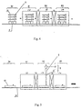
- FIG. 4 An embodiment of the present invention is shown in Fig. 4, wherein multiple starting sheets of vacuum glazing are placed with a space between them, and edge-sealed, evacuated and hole-sealed simultaneously, to produce multiple sheets of the vacuum glazing.
- the production of vacuum glazing can be conducted in a chamber or several chambers, as shown in Fig. 4, 5 and 6, respectively.
- the said manufacturing method according to the present invention can be implemented to produce eligible vacuum glazing products by adopting a plurality of embodiments.
- Fig. 4 and 5 illustrate a device system for manufacturing vacuum glazing, comprising: the starting sheets conveying part 30, e.g. a bracket 11, continuous moving or step-by-step moving roll or belt conveyor 35, used to convey the starting sheets; the heating and sealing part 31: with a heating means (member), e. g. the usual electric heater or air heater device, used to heat the placed starting sheets to the melting temperature of the edge-sealing glass powders; evacuating part 32: with an evacuating means, e. g. the usual vacuum pump and pipes, used to evacuate the edge-sealed glass sheets together with the said vacuum chamber to the required vacuity; hole-sealing member 9, e. g.
- cooling part e. g. the usual air-cooling, water-cooling device, used to cool the hole-sealed glass sheets, thus obtaining the vacuum glazing with the required vacuity.
- the said hole-sealing member 9 is a hole-sealing coil fixed previously on the evacuating glass hole 4, an electric current such as AC, DC or high frequency can be provided to it, to heat the evacuating glass hole 4 and to make it sealed.
- the said hole-sealing member 9 can also be a window 9', through which infrared or laser radiation can pass, as well as an infrared or laser heater 9" located outside of the said vacuum chamber 13, by which the evacuating glass hole 4 is heated and sealed; or an infrared of laser heating device located within the said vacuum chamber, by which the evacuating glass hole 4 is heated and sealed.
- the said conveying part 30 is the bracket 11, which is used to place laminatedly at least two starting sheets of vacuum glazing in different layer and to convey the same, thereby forming multiple sheets of vacuum glazing. Furthermore, the said conveying part 30 can also be the continuous moving or step-by-step moving roll or belt conveyor 35.
- the device shown in Fig. 5 is used to convey one starting sheet of vacuum glazing each time, thus forming one sheet of vacuum glazing each time.
- a first buffer chamber 15 and a second buffer chamber 16 which are used to adjust the vacuity and temperature, are arranged between the said heating and sealing part 31 and the evacuating part 32 and/or between the said evacuating part 32 and the cooling part 33, to make the glass sheets to be pre-evacuated and/or adjust their temperature from the edge-sealing temperature to the evacuating temperature, as well as to make the hole-sealed glass sheets enter into a low vacuum chamber and/or to adjust their temperature so as to enter the cooling chamber, respectively.
- a preheating part is also arranged before the heating and edge-sealing part 31, to preheat the placed starting sheet of vacuum glazing.
- the said device for manufacturing vacuum glazing also comprises temperature measuring means and/or vacuity measuring means.
- the said parts 31, 32 and 33 designate several chambers in series, for example, as shown in Fig. 4 and 5.
- the said parts 31, 32 and 33 are all located within one chamber, for example, as shown in Fig. 6A and B.
- a process embodiment of manufacturing vacuum glazing in a multiple sheets way will be described referring to Fig. 4.
- the coils 9 for sealing the holes are fixed previously at the location of the evacuating tubes 4 on the glass sheets, and connected to the power.
- the bracket first enters the heating chamber (the first chamber) 12, and is heated to the melting temperature of the edge-sealing glass powder, that is, about 300 - 550°C, then is cooled to solidify the edge-sealing glass powder, and the edge-sealing is completed.
- the bracket 11 then passes through the optional first buffer chamber (the second chamber) 15 and enters the vacuum chamber (the third chamber) 13.
- the evacuation begins.
- the hole-sealing begins by switching on the electric power (AC, DC or high frequency) of the hole-sealing member to seal the holes. Then, the bracket 11 pass through an optional second buffer chamber (the fourth chamber) 16 and enter the cooling furnace (the fifth chamber) 14 to conduct the cooling, then removing out from the furnace.
- AC electric power
- the said first and second buffer chambers 15, 16 functions as adjusting the vacuity and the temperature, to make the glass sheets pre-evacuated and/or to adjust the temperature from the edge-sealing temperature to the evacuating temperature, and to make the vacuum glazing sheets after the holes are sealed enters a low vacuum chamber and/or to adjust the temperature from the evacuating temperature to the temperature for entering the cooling chamber.
- These two buffer chambers can be omitted sometimes.
- Fig.5 is the process embodiment of manufacturing vacuum glazing in a single-sheet way.
- the starting sheet 10 of vacuum glazing which has been arranged first enters the heating chamber to seal the edges, then enters the a flat vacuum chamber 13 to evacuate, at this time the hole-sealing can be conducted by means of the infrared spotlight or laser radiation 9" located outside or inside of the vacuum chamber, or by means of the hole-sealing coils 9 fixed in the vacuum chamber, then enters the cooling chamber 14 to be cooled and discharged. Since it is unnecessary for the hole-sealing coil to be fixed on the vacuum glazing, the embodiment apparently brings about many convenient benefits.
- the said first and the second buffer chamber described above can also be used in the embodiment.
- a preheating chamber is preferably arranged before the heating chamber 12, so as to preheat the conveying starting sheets 10 of vacuum glazing before they enter the heating chamber 12.
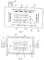
- Fig. 6A and 6B illustrate schematically a device for manufacturing vacuum glazing by means of a single chamber according to a preferable example of the present invention.
- the apparent difference between this embodiment and the two other embodiments described above is that the main steps, such as the said heating, evacuating, cooling, etc., are all completed in a single chamber and it is not necessary to adopt several continuous chambers.
- Fig. 6A several starting sheets of vacuum glazing, which have been properly arranged, placed laminatedly on the conveying device such as bracket 11, then put the bracket into the vacuum chamber 5, wherein the vacuum chamber 5 is provided with a heater 8, an insulating layer 29, a temperature measuring device 27 and a vacuity measuring device 28.
- the vacuum chamber 5 is heated to the melting temperature of the edge-sealing glass powder, that is, a temperature from about 300 to about 550°C, then is cooled to make the edge-sealing glass powder solidify, and so the edge-sealing is completed.
- the evacuation begins by means of the evacuating pipe 6 and the evacuating device 7.
- the vacuity reached to 10 -1 to 10 -4 Pa, preferably 10 -2 to 10 -4 Pa
- the hole-sealing mechanism starts to seal the holes.
- the vacuum chamber 5 is cooled, and then the vacuum glazing is removed from the chamber. Unlike Fig. 6A, in Fig.
- the heater 8 is a fan 8' which can be adjusted to heat or cool. That is to say, in Fig. 6B, heating is carried out in the hot air heating manner, while cooling can be carried out by means of the cool air outside of the chamber, and the other structures can be remained unchanged. This is helpful to increase the temperature uniformity and the heating efficiency.
- the heater 8 in Fig. 6A can also be replaced by a fan which can be adjusted to heat or cool.
- the hole-sealing mechanism can be an infrared lamp, a laser or a heating coil.
- a shield 11' with a window which can be opened or closed, can be arranged on the conveyor 11, to function as thermal insulation. After the holes are sealed, the vacuum glazing products can be removed from the chamber at high temperature under the protection of the closed shield, and another semi finished article conveyor can enter the chamber which is at high temperature, therefore, the operation efficiency is improved and the energy consumption is reduced.
- a preheating step can be arranged before the heating step so that the glass sheets can be preheated, for example, by making use of the afterheat of the cooling process.
- the device for manufacturing vacuum glazing is used to produce vacuum glazing from a starting sheet of vacuum glazing 10 which comprises two pieces of glass 1a, 1b placed oppositely, between which there is a space.
- a plurality of supports 2 are placed in the space to keep it, wherein at least one of the pieces of glass has a hole, which communicates with a space formed between the two pieces of glass and is used to evacuate.
- the device includes:
- it further comprises a fourth chamber 16 connected with the third chamber 13 by a vacuum valve, the fourth chamber 16 can reach a third vacuity and a fourth temperature, wherein the third vacuity is lower than the second vacuity and the fourth temperature is lower than the third temperature.
- the third vacuity is for example 10 -1 Pa.
- it further comprises a fifth chamber 14 connected with the fourth chamber 16 through a vacuum valve, and the fifth chamber 14 has a fifth temperature and a ordinary pressure, wherein the fifth temperature is lower than the fourth temperature, and the temperature of the fifth chamber can be cooled in a scheduled gradient.
- it further comprises a preheating chamber before the first chamber 12, used to preheat the starting sheets of vacuum glazing.
- the edge-sealing step, the evacuating step and the hole-sealing step describe above are conducted in a temperature range of 200 to 550°C, preferably 300 to 510°C.
- One of the advantages of the manner is that it is unnecessary to reduce the temperature to a very low temperature after the edge-sealing step. This has the effects of both saving energy and time, on the other hand, the starting sheets of vacuum glazing subjects to less thermal shock, thereby improving the yield of finished vacuum glazing.
- a preferable operation procedure will be described as following.
- the sealing glass has been arranged on the edges of the starting sheet of vacuum glazing, the sealing glass and the glass tube for sealing have been arranged on its evacuating hole.
- the structure described above enters the first chamber 12, being heated to the melting temperature of the sealing glass to make the edges of the starting sheet to be sealed while the glass tube for sealing being air-tightly connected to the evacuating hole.
- the resulting structure is conveyed to the second chamber 15, in which it subjects to a proper temperature falling and a primary evacuation.
- the resulting structure is then conveyed to the third chamber 13, in which it subjects to a further evacuation to a higher vacuity of about 10 -1 to 10 -4 Pa, preferably up to 10 -2 to 10 -4 Pa.
- the glass tube for sealing is heated to melt and to seal the evacuation hole.
- the obtained structure is conveyed to the fourth chamber 16.
- the fourth chamber 16 has a vacuity of about 10 -1 Pa, and is connected with the third chamber through a vacuum valve, so that the high vacuity of the third chamber may not be interrupted excessively, especially that the operation time can be reduced. It is the best way to convey the obtained structure into the fifth chamber 14 to reduce the temperature gradually.
- the chamber 14 is under a normal pressure so as to reduce the temperature controllably.
- a device for manufacturing vacuum glazing according to another preferable embodiment will be described combining with Fig. 7A and 7B.
- the said device comprises:
- the shield has a ventilative widow which can be opened or closed, for example with a shutter or sliding plate type structure.
- a ventilative widow which can be opened or closed, for example with a shutter or sliding plate type structure.
- a method for manufacturing vacuum glazing according to a preferable embodiment of the present invention comprises the following steps:
- the conveyor with a shield 11a and in which the charged vacuum glazing has been sealed can be removed directly without reducing the temperature of the whole chamber 5 after the edge-sealing operation, evacuating operation and the hole-sealing of the start sheets of vacuum glazing on a conveyor has been completed, thus another charged conveyor can directly enter into the chamber 5 without reducing its temperature, thereby having an efficient and energy saving effects.
- the temperature reduction of the vacuum glazing enclosed in the shield 11a and outside of the chamber 5 is easy to control. Especially for the shield having the first and the second state, this is beneficial to control the falling rate of the temperature within the shield after it is removed from the elevated temperature chamber.
Landscapes
- Engineering & Computer Science (AREA)
- Chemical & Material Sciences (AREA)
- Civil Engineering (AREA)
- Structural Engineering (AREA)
- Ceramic Engineering (AREA)
- Life Sciences & Earth Sciences (AREA)
- Chemical Kinetics & Catalysis (AREA)
- General Chemical & Material Sciences (AREA)
- Geochemistry & Mineralogy (AREA)
- Materials Engineering (AREA)
- Organic Chemistry (AREA)
- Joining Of Glass To Other Materials (AREA)
Applications Claiming Priority (1)
| Application Number | Priority Date | Filing Date | Title |
|---|---|---|---|
| PCT/CN1999/000129 WO2001016045A1 (fr) | 1999-08-27 | 1999-08-27 | Procede de fabrication de vitrage sous vide et systeme mecanique d'application |
Publications (1)
| Publication Number | Publication Date |
|---|---|
| EP1216971A1 true EP1216971A1 (fr) | 2002-06-26 |
Family
ID=4575139
Family Applications (1)
| Application Number | Title | Priority Date | Filing Date |
|---|---|---|---|
| EP99939904A Withdrawn EP1216971A1 (fr) | 1999-08-27 | 1999-08-27 | Procede de fabrication de vitrage sous vide et systeme mecanique d'application |
Country Status (4)
| Country | Link |
|---|---|
| EP (1) | EP1216971A1 (fr) |
| CN (1) | CN1263698C (fr) |
| AU (1) | AU5406399A (fr) |
| WO (1) | WO2001016045A1 (fr) |
Cited By (13)
| Publication number | Priority date | Publication date | Assignee | Title |
|---|---|---|---|---|
| WO2009078911A1 (fr) * | 2007-12-14 | 2009-06-25 | Guardian Industries Corp. | Techniques de pompage et de scellement d'orifice pour des unités de verre isolant sous vide, et/ou four à vide permettant d'effectuer ces techniques |
| EP2292887A3 (fr) * | 2007-12-14 | 2011-05-18 | Guardian Industries Corp. | Chauffage localisé de scellements de bord pour une unité de verre isolant sous vide et/ou four unifié permettant d'effectuer ce chauffage |
| US8227055B2 (en) | 2009-05-01 | 2012-07-24 | Guardian Industries Corp. | Vacuum insulating glass unit including infrared meltable glass frit, and/or method of making the same |
| CN101324168B (zh) * | 2008-06-03 | 2012-09-05 | 陈建明 | 一种多功能钢化中空玻璃窗 |
| US8506738B2 (en) * | 2007-12-17 | 2013-08-13 | Guardian Industries Corp. | Localized heating via an infrared heat source array of edge seals for a vacuum insulating glass unit, and/or unitized oven with infrared heat source array for accomplishing the same |
| KR101485090B1 (ko) * | 2010-11-23 | 2015-01-21 | 루오양 랜드글라스 테크놀로지 컴퍼니 리미티드 | 진공 유리 밀봉 장치 |
| JP2015523949A (ja) * | 2012-05-18 | 2015-08-20 | ガーディアン・インダストリーズ・コーポレーション | 排気管封止法を含む真空断熱ガラス(vig)窓ユニットの製造方法及び製造装置 |
| US9488318B2 (en) | 2012-08-28 | 2016-11-08 | Mb-Microtec Ag | Process for producing a self-illuminating body and self-illuminating body |
| US9572273B2 (en) | 2012-08-28 | 2017-02-14 | Mb-Microtec Ag | Method for producing a hermetic housing for an electronic device |
| US9822580B2 (en) | 2011-02-22 | 2017-11-21 | Guardian Glass, LLC | Localized heating techniques incorporating tunable infrared element(s) for vacuum insulating glass units, and/or apparatuses for same |
| KR101845004B1 (ko) | 2015-06-22 | 2018-04-03 | 김광식 | 진공 유리 제조장치 및 제조방법 |
| EP3438400A4 (fr) * | 2016-03-31 | 2019-03-20 | Panasonic Intellectual Property Management Co., Ltd. | Procédé de production d'unités de panneaux de verre, procédé de production de monture, dispositif de production d'unités de panneaux de verre et unité de panneau de verre |
| RU2841590C1 (ru) * | 2024-07-19 | 2025-06-10 | Юйвэй ЦЮЙ | Способ изготовления вакуумного стекла |
Families Citing this family (47)
| Publication number | Priority date | Publication date | Assignee | Title |
|---|---|---|---|---|
| GB0211230D0 (en) | 2002-05-16 | 2002-06-26 | Medinnova Sf | Treatment of heart failure |
| JP5068924B2 (ja) * | 2004-02-20 | 2012-11-07 | 中外炉工業株式会社 | ガラスパネル組立体の連続封着処理炉および封着処理方法 |
| FR2869898B1 (fr) * | 2004-05-05 | 2007-03-30 | Saint Gobain | Substrat muni d'un empilement a proprietes thermiques |
| CN1298654C (zh) * | 2004-06-09 | 2007-02-07 | 王及伟 | 真空玻璃百页的制造方法 |
| CN1907895B (zh) * | 2005-08-02 | 2010-05-05 | 王世忠 | 生产建筑真空玻璃板的真空焊接炉 |
| CN1903759B (zh) * | 2006-08-10 | 2010-08-04 | 刘元生 | 一种真空玻璃的生产方法 |
| CN101148313B (zh) * | 2006-09-20 | 2011-01-12 | 黄家军 | 一步成型真空玻璃及其制造方法和设备 |
| CN101234847B (zh) * | 2007-01-30 | 2010-07-21 | 辽宁北方玻璃机械有限公司 | 连续式真空玻璃封边炉 |
| EP1978199B1 (fr) * | 2007-04-05 | 2016-05-25 | Grenzebach Maschinenbau GmbH | Composant en verre isolant du vide et procédé et dispositif de fabrication |
| CN101298370B (zh) * | 2008-03-21 | 2011-06-08 | 胡屹博 | 低温粘和平板真空玻璃的制作方法及其设备 |
| CN101725307B (zh) * | 2008-10-17 | 2012-05-30 | 董祥义 | 一种制备高效节能真空玻璃的加工方法 |
| CN102173605B (zh) * | 2011-01-28 | 2015-12-02 | 东莞市银通玻璃有限公司 | 一种真空玻璃的制造方法 |
| CN102219401B (zh) * | 2011-03-08 | 2013-04-24 | 李梦琪 | 平板物料制造系统 |
| CN102690046B (zh) * | 2011-03-22 | 2016-01-13 | 黄家军 | 一种真空玻璃封边方法 |
| CN102320726B (zh) * | 2011-06-20 | 2013-07-10 | 天津沽上真空玻璃制造有限公司 | 一种真空玻璃竖立抽气的制备工艺 |
| CN102295404B (zh) * | 2011-06-20 | 2013-06-26 | 天津沽上真空玻璃制造有限公司 | 一种真空玻璃的制造工艺 |
| CN102863145A (zh) * | 2011-07-05 | 2013-01-09 | 黄家军 | 一种真空玻璃封接方法 |
| CN102863158B (zh) * | 2011-07-05 | 2014-09-10 | 洛阳兰迪玻璃机器股份有限公司 | 真空玻璃封接方法及装置 |
| CN102503095A (zh) * | 2011-10-28 | 2012-06-20 | 天津森宇玻璃制造有限公司 | 一种真空玻璃抽气孔在真空状态下的熔封结构 |
| CN103086589B (zh) * | 2011-10-28 | 2015-07-29 | 黄家军 | 一种真空玻璃压差封接方法 |
| CN102503094B (zh) * | 2011-10-28 | 2013-09-25 | 天津森宇玻璃制造有限公司 | 一种常压封边、真空炉内低压封口的真空玻璃的制造方法 |
| CN102503097A (zh) * | 2011-10-28 | 2012-06-20 | 天津森宇玻璃制造有限公司 | 一种红外线加热法熔封抽气孔的方法 |
| CN102503096B (zh) * | 2011-10-28 | 2014-04-30 | 天津森宇玻璃制造有限公司 | 利用控温控压法在真空加热炉内制得真空玻璃的方法 |
| CN102491626B (zh) * | 2011-11-16 | 2013-11-06 | 天津森宇玻璃制造有限公司 | 一种真空炉内制得真空玻璃的方法 |
| CN102515534B (zh) * | 2011-12-08 | 2013-12-11 | 林嘉宏 | 玻璃封装溶胶和制备方法以及玻璃封装方法及其真空玻璃 |
| CN102512089A (zh) * | 2012-01-06 | 2012-06-27 | 苏州雷嘉电子科技有限公司 | 一种真空保温器皿的制造工艺及设备 |
| CN102557490B (zh) * | 2012-01-18 | 2014-10-15 | 林嘉宏 | 全自动真空玻璃制造设备及其制造工艺 |
| CN103241929B (zh) * | 2012-02-13 | 2015-08-26 | 洛阳兰迪玻璃机器股份有限公司 | 连续式真空室 |
| CN102674711B (zh) * | 2012-05-17 | 2015-05-20 | 潍坊亚通玻璃制品有限公司 | 一种真空玻璃的制备方法 |
| CN103570229B (zh) * | 2012-08-10 | 2015-11-25 | 北京新立基真空玻璃技术有限公司 | 真空抽取装置、真空玻璃制作系统以及相关方法 |
| CN104030557B (zh) * | 2014-06-26 | 2016-04-13 | 滕少波 | 真空玻璃的制备方法 |
| CN106431018A (zh) * | 2015-08-10 | 2017-02-22 | 东元奈米应材股份有限公司 | 真空绝缘玻璃封着及抽气方法 |
| CN105967534A (zh) * | 2016-05-11 | 2016-09-28 | 戴婷婷 | 一种汽车用钢化真空夹胶玻璃的制备工艺 |
| CN107449549A (zh) * | 2017-08-16 | 2017-12-08 | 彩虹集团新能源股份有限公司 | 一种检测真空玻璃真空度的石英管装置及其检测方法 |
| CN107915415A (zh) * | 2017-12-29 | 2018-04-17 | 左宪恤 | 连续式真空玻璃制备装置及制备方法 |
| KR101959167B1 (ko) * | 2018-06-29 | 2019-03-15 | 김진방 | 이중 진공유리 제조방법과 이에 의해 제조되는 이중 진공유리 |
| CN111662018A (zh) * | 2019-03-07 | 2020-09-15 | 左宪恤 | 吸附定位式抽真空装置及使用方法 |
| CN111847903B (zh) * | 2019-04-26 | 2024-08-27 | 山东晟芳铭玻璃科技有限公司 | 封装装置 |
| CN110332097B (zh) * | 2019-05-21 | 2021-10-22 | 洛阳兰迪玻璃机器股份有限公司 | 一种真空玻璃抽气方法及抽气装置 |
| CN110467361A (zh) * | 2019-09-03 | 2019-11-19 | 北京环健畅想量子科技有限公司 | 一种真空玻璃的生产装置及方法 |
| CN110682633A (zh) * | 2019-11-04 | 2020-01-14 | 青岛锦绣前程节能玻璃有限公司 | 一种真空连续式夹胶玻璃生产方法 |
| CN111977992A (zh) * | 2020-08-26 | 2020-11-24 | 广西创兴玻璃科技有限公司 | 一种防火玻璃的制备方法 |
| CN113277751B (zh) * | 2020-09-30 | 2023-08-22 | 江苏景泰玻璃有限公司 | 一种真空玻璃生产用烘干装置及其烘干方法 |
| CN112142343A (zh) * | 2020-10-20 | 2020-12-29 | 左宪楠 | 一种批量制造真空玻璃的装置及方法 |
| CN112159122A (zh) * | 2020-10-22 | 2021-01-01 | 辽宁北方玻璃机械股份有限公司 | 一种生产一步法真空玻璃的高温负压真空釜 |
| CN114951879A (zh) * | 2022-06-08 | 2022-08-30 | 希诺股份有限公司 | 一种真空保温杯低温高效抽真空密封设备及密封工艺 |
| CN118164691B (zh) * | 2024-03-18 | 2024-08-27 | 江苏大煦朗宁新材料科技有限公司 | 玻璃真空封口设备及其在半导体用石英管生产中的应用 |
Family Cites Families (5)
| Publication number | Priority date | Publication date | Assignee | Title |
|---|---|---|---|---|
| US4683154A (en) * | 1985-08-19 | 1987-07-28 | The United States Of America As Represented By The United States Department Of Energy | Laser sealed vacuum insulation window |
| JPH0617579A (ja) * | 1992-04-06 | 1994-01-25 | Kazuo Kuroiwa | 真空断熱ガラス板及びその製造方法 |
| CN2163856Y (zh) * | 1993-06-21 | 1994-05-04 | 李国业 | 普及型真空保温玻璃 |
| EP0645516B1 (fr) * | 1993-09-27 | 2002-01-23 | Saint-Gobain Glass France | Procédé pour réaliser le vide dans un vitrage isolant et vitrage isolant |
| CN1046150C (zh) * | 1995-07-25 | 1999-11-03 | 青岛新立基技术应用有限公司 | 真空平板玻璃及其制造方法 |
-
1999
- 1999-08-27 AU AU54063/99A patent/AU5406399A/en not_active Abandoned
- 1999-08-27 WO PCT/CN1999/000129 patent/WO2001016045A1/fr not_active Ceased
- 1999-08-27 EP EP99939904A patent/EP1216971A1/fr not_active Withdrawn
- 1999-08-27 CN CNB998015539A patent/CN1263698C/zh not_active Expired - Lifetime
Non-Patent Citations (1)
| Title |
|---|
| See references of WO0116045A1 * |
Cited By (29)
| Publication number | Priority date | Publication date | Assignee | Title |
|---|---|---|---|---|
| US9677320B2 (en) | 2007-12-14 | 2017-06-13 | Guardian Industries Corp. | Evacuation and port sealing techniques for vacuum insulating glass units, and/or vacuum oven for accomplishing the same |
| EP2292887A3 (fr) * | 2007-12-14 | 2011-05-18 | Guardian Industries Corp. | Chauffage localisé de scellements de bord pour une unité de verre isolant sous vide et/ou four unifié permettant d'effectuer ce chauffage |
| US8460493B2 (en) | 2007-12-14 | 2013-06-11 | Guardian Industries Corp. | Evacuation and port sealing techniques for vacuum insulating glass units, and/or vacuum oven for accomplishing the same |
| US8500933B2 (en) * | 2007-12-14 | 2013-08-06 | Guardian Industries Corp. | Localized heating of edge seals for a vacuum insulating glass unit, and/or unitized oven for accomplishing the same |
| WO2009078911A1 (fr) * | 2007-12-14 | 2009-06-25 | Guardian Industries Corp. | Techniques de pompage et de scellement d'orifice pour des unités de verre isolant sous vide, et/ou four à vide permettant d'effectuer ces techniques |
| US10703667B2 (en) | 2007-12-14 | 2020-07-07 | Guardian Glass, LLC | Localized heating of edge seals for a vacuum insulating glass unit, and/or unitized oven for accomplishing the same |
| US10221613B2 (en) | 2007-12-14 | 2019-03-05 | Guardian Glass, LLC | Evacuation and port sealing techniques for vacuum insulating glass units |
| EP2231984B1 (fr) * | 2007-12-14 | 2019-01-23 | Guardian Glass, LLC | Chauffage localisé de scellements de bord pour une unité de verre isolant sous vide et/ou four unifié permettant d'effectuer ce chauffage |
| US10717668B2 (en) | 2007-12-17 | 2020-07-21 | Guardian Glass, Llc. | Localized heating via an infrared heat source array of edge seals for a vacuum insulating glass unit, and/or unitized oven with infrared heat source array for accomplishing the same |
| US8506738B2 (en) * | 2007-12-17 | 2013-08-13 | Guardian Industries Corp. | Localized heating via an infrared heat source array of edge seals for a vacuum insulating glass unit, and/or unitized oven with infrared heat source array for accomplishing the same |
| US10294140B2 (en) | 2007-12-17 | 2019-05-21 | Guardian Glass, LLC | Localized heating via an infrared heat source array of edge seals for a vacuum insulating glass unit, and/or unitized oven with infrared heat source array for accomplishing the same |
| CN101324168B (zh) * | 2008-06-03 | 2012-09-05 | 陈建明 | 一种多功能钢化中空玻璃窗 |
| US8590343B2 (en) | 2009-05-01 | 2013-11-26 | Guardian Industries Corp. | Vacuum insulating glass unit including infrared meltable glass frit, and/or method of making the same |
| US8227055B2 (en) | 2009-05-01 | 2012-07-24 | Guardian Industries Corp. | Vacuum insulating glass unit including infrared meltable glass frit, and/or method of making the same |
| US8763427B2 (en) | 2009-05-01 | 2014-07-01 | Guardian Industries Corp. | Vacuum insulating glass unit including infrared meltable glass frit, and/or method of making the same |
| KR101485090B1 (ko) * | 2010-11-23 | 2015-01-21 | 루오양 랜드글라스 테크놀로지 컴퍼니 리미티드 | 진공 유리 밀봉 장치 |
| US9822580B2 (en) | 2011-02-22 | 2017-11-21 | Guardian Glass, LLC | Localized heating techniques incorporating tunable infrared element(s) for vacuum insulating glass units, and/or apparatuses for same |
| JP2015523949A (ja) * | 2012-05-18 | 2015-08-20 | ガーディアン・インダストリーズ・コーポレーション | 排気管封止法を含む真空断熱ガラス(vig)窓ユニットの製造方法及び製造装置 |
| US9572273B2 (en) | 2012-08-28 | 2017-02-14 | Mb-Microtec Ag | Method for producing a hermetic housing for an electronic device |
| US9488318B2 (en) | 2012-08-28 | 2016-11-08 | Mb-Microtec Ag | Process for producing a self-illuminating body and self-illuminating body |
| KR101845004B1 (ko) | 2015-06-22 | 2018-04-03 | 김광식 | 진공 유리 제조장치 및 제조방법 |
| EP3438400A4 (fr) * | 2016-03-31 | 2019-03-20 | Panasonic Intellectual Property Management Co., Ltd. | Procédé de production d'unités de panneaux de verre, procédé de production de monture, dispositif de production d'unités de panneaux de verre et unité de panneau de verre |
| EP3438399A4 (fr) * | 2016-03-31 | 2019-03-20 | Panasonic Intellectual Property Management Co., Ltd. | Procédé de fabrication d'ensemble panneau de verre, procédé de fabrication de raccord de fixation, dispositif de fabrication d'ensemble panneau de verre, et ensemble panneau de verre |
| EP3438401A4 (fr) * | 2016-03-31 | 2019-03-20 | Panasonic Intellectual Property Management Co., Ltd. | Procédé de production d'unités de panneaux de verre, procédé de production de monture, dispositif de production d'unités de panneaux de verre et unité de panneau de verre |
| US10858279B2 (en) | 2016-03-31 | 2020-12-08 | Panasonic Intellectual Property Management Co., Ltd. | Glass panel unit manufacturing method, building component manufacturing method, glass panel unit manufacturing system, and glass panel unit |
| US10941068B2 (en) | 2016-03-31 | 2021-03-09 | Panasonic Intellectual Property Management Co., Ltd. | Glass panel unit manufacturing method, building component manufacturing method, glass panel unit manufacturing system, and glass panel unit |
| US10974985B2 (en) | 2016-03-31 | 2021-04-13 | Panasonic Intellectual Property Management Co., Ltd. | Glass panel unit manufacturing method, building component manufacturing method, glass panel unit manufacturing system, and glass panel unit |
| US11254600B2 (en) | 2016-03-31 | 2022-02-22 | Panasonic Intellectual Property Management Co., Ltd. | Glass panel unit manufacturing method, building component manufacturing method, glass panel unit manufacturing system, and glass panel unit |
| RU2841590C1 (ru) * | 2024-07-19 | 2025-06-10 | Юйвэй ЦЮЙ | Способ изготовления вакуумного стекла |
Also Published As
| Publication number | Publication date |
|---|---|
| CN1263698C (zh) | 2006-07-12 |
| AU5406399A (en) | 2001-03-26 |
| WO2001016045A1 (fr) | 2001-03-08 |
| HK1035522A1 (en) | 2001-11-30 |
| CN1286670A (zh) | 2001-03-07 |
Similar Documents
| Publication | Publication Date | Title |
|---|---|---|
| CN1263698C (zh) | 真空玻璃的制造方法及其装置 | |
| EP3392214B1 (fr) | Procédé de fabrication de verre sous vide trempé et ligne de production associée | |
| US10221613B2 (en) | Evacuation and port sealing techniques for vacuum insulating glass units | |
| JP6293124B2 (ja) | 排気管封止法を含む真空断熱ガラス(vig)窓ユニットの製造方法及び製造装置 | |
| US6827623B2 (en) | Manufacturing method of plasma display panels | |
| EP3363983B1 (fr) | Unité de vitrage isolée sous vide | |
| JP2015518810A (ja) | 排気管を備えた真空断熱ガラス(vig)窓ユニットの製造方法及び製造装置 | |
| US11130706B2 (en) | Methods for manufacturing tempered vacuum glass and production lines therefor | |
| JP3946319B2 (ja) | プラズマディスプレイパネルの処理方法 | |
| CN109184486A (zh) | 制备真空绝缘玻璃窗单元的方法 | |
| JP3554432B2 (ja) | プラズマディスプレイパネルの製造方法 | |
| CA2329086A1 (fr) | Lampe a decharge plate et son procede de production | |
| CN102173605B (zh) | 一种真空玻璃的制造方法 | |
| US4923423A (en) | Integrated thermal processing for kinescopes | |
| JP3189786B2 (ja) | プラズマディスプレイパネルの製造方法 | |
| KR101086081B1 (ko) | 유리 패널 조립체의 연속 봉착 처리로 및 봉착 처리 방법 | |
| HK1035522B (en) | A method and an apparatus for making a vacuum glass | |
| CA2488707A1 (fr) | Procede de fabrication d'un dispositif a decharge gazeuse | |
| KR920010370B1 (ko) | 칼라수상관의 판넬과 훤넬봉합 및 배기방법 | |
| JPS6057176B2 (ja) | 陰極線管の製造方法 | |
| US2956374A (en) | Glass bulb fabrication | |
| JPH0517648B2 (fr) |
Legal Events
| Date | Code | Title | Description |
|---|---|---|---|
| PUAI | Public reference made under article 153(3) epc to a published international application that has entered the european phase |
Free format text: ORIGINAL CODE: 0009012 |
|
| 17P | Request for examination filed |
Effective date: 20020222 |
|
| AK | Designated contracting states |
Kind code of ref document: A1 Designated state(s): AT BE CH CY DE DK ES FI FR GB GR IE IT LI LU MC NL PT SE |
|
| AX | Request for extension of the european patent |
Free format text: AL;LT;LV;MK;RO;SI |
|
| RAP1 | Party data changed (applicant data changed or rights of an application transferred) |
Owner name: BEIJING SYNERGY VACUUM GLAZING TECHNOLOGY CO., LTD |
|
| STAA | Information on the status of an ep patent application or granted ep patent |
Free format text: STATUS: THE APPLICATION IS DEEMED TO BE WITHDRAWN |
|
| 18D | Application deemed to be withdrawn |
Effective date: 20030301 |
|
| RBV | Designated contracting states (corrected) |
Designated state(s): BE DE FR GB |