EP1220053A2 - Bilderzeugungsgerät und Verfahren zur Steuerung eines Kühlgebläses - Google Patents
Bilderzeugungsgerät und Verfahren zur Steuerung eines Kühlgebläses Download PDFInfo
- Publication number
- EP1220053A2 EP1220053A2 EP01130620A EP01130620A EP1220053A2 EP 1220053 A2 EP1220053 A2 EP 1220053A2 EP 01130620 A EP01130620 A EP 01130620A EP 01130620 A EP01130620 A EP 01130620A EP 1220053 A2 EP1220053 A2 EP 1220053A2
- Authority
- EP
- European Patent Office
- Prior art keywords
- transfer sheet
- cooling fan
- controlling
- conveyance
- revolving
- Prior art date
- Legal status (The legal status is an assumption and is not a legal conclusion. Google has not performed a legal analysis and makes no representation as to the accuracy of the status listed.)
- Withdrawn
Links
- 238000012546 transfer Methods 0.000 title claims abstract description 591
- 238000001816 cooling Methods 0.000 title claims abstract description 380
- 238000000034 method Methods 0.000 title claims description 125
- 238000004590 computer program Methods 0.000 title claims 3
- 238000007599 discharging Methods 0.000 claims abstract description 37
- 238000012545 processing Methods 0.000 claims description 2
- 230000000694 effects Effects 0.000 description 28
- 230000015654 memory Effects 0.000 description 23
- 238000007639 printing Methods 0.000 description 16
- 238000012840 feeding operation Methods 0.000 description 15
- 239000002245 particle Substances 0.000 description 7
- 230000015572 biosynthetic process Effects 0.000 description 4
- 238000004891 communication Methods 0.000 description 4
- 238000005259 measurement Methods 0.000 description 4
- 230000007423 decrease Effects 0.000 description 2
- 238000010586 diagram Methods 0.000 description 2
- 230000002159 abnormal effect Effects 0.000 description 1
- 230000003247 decreasing effect Effects 0.000 description 1
- 238000005516 engineering process Methods 0.000 description 1
- 230000005764 inhibitory process Effects 0.000 description 1
- 238000012986 modification Methods 0.000 description 1
- 230000004048 modification Effects 0.000 description 1
- 238000012163 sequencing technique Methods 0.000 description 1
Images






Classifications
-
- G—PHYSICS
- G03—PHOTOGRAPHY; CINEMATOGRAPHY; ANALOGOUS TECHNIQUES USING WAVES OTHER THAN OPTICAL WAVES; ELECTROGRAPHY; HOLOGRAPHY
- G03G—ELECTROGRAPHY; ELECTROPHOTOGRAPHY; MAGNETOGRAPHY
- G03G15/00—Apparatus for electrographic processes using a charge pattern
- G03G15/20—Apparatus for electrographic processes using a charge pattern for fixing, e.g. by using heat
- G03G15/2003—Apparatus for electrographic processes using a charge pattern for fixing, e.g. by using heat using heat
-
- G—PHYSICS
- G03—PHOTOGRAPHY; CINEMATOGRAPHY; ANALOGOUS TECHNIQUES USING WAVES OTHER THAN OPTICAL WAVES; ELECTROGRAPHY; HOLOGRAPHY
- G03G—ELECTROGRAPHY; ELECTROPHOTOGRAPHY; MAGNETOGRAPHY
- G03G21/00—Arrangements not provided for by groups G03G13/00 - G03G19/00, e.g. cleaning, elimination of residual charge
- G03G21/20—Humidity or temperature control also ozone evacuation; Internal apparatus environment control
- G03G21/206—Conducting air through the machine, e.g. for cooling, filtering, removing gases like ozone
-
- G—PHYSICS
- G03—PHOTOGRAPHY; CINEMATOGRAPHY; ANALOGOUS TECHNIQUES USING WAVES OTHER THAN OPTICAL WAVES; ELECTROGRAPHY; HOLOGRAPHY
- G03G—ELECTROGRAPHY; ELECTROPHOTOGRAPHY; MAGNETOGRAPHY
- G03G2215/00—Apparatus for electrophotographic processes
- G03G2215/00362—Apparatus for electrophotographic processes relating to the copy medium handling
- G03G2215/00535—Stable handling of copy medium
- G03G2215/00717—Detection of physical properties
- G03G2215/00721—Detection of physical properties of sheet position
Definitions
- the present invention generally relates to an image-forming device, a recording medium, and an image-forming device controlling method, and more particularly, to an image-forming device, such as a printer incorporating a heat-fixing device, and a multifunctional copying machine, to a recording medium, and to an image-forming device controlling method.
- an image-forming device such as a printer or a copying machine, which performs a printing by a heat-fixing method
- a toner image formed on a photosensitive member is transferred to a recording paper by using an electrostatic power, and thereafter the recording paper bearing the toner image is conveyed to a heat-fixing device.
- a predetermined fixing heat is applied to the toner image on the recording paper under pressure imposed by nip portions of the fixing roller and the pressuring roller so as to fix the toner image on the recording paper.
- a heat-fixing device generally incorporates a heater generating a Joule heat in the fixing roller.
- the electrophotographic recording device further comprises a cooling fan revolving so as to prevent the temperature rise in the device.
- the cooling fan is often laid out in the vicinity of the heat-fixing device; therefore, when the recording paper (especially the leading end thereof) enters the heat-fixing device, toner particles transferred to the recording paper flow around due to an air current generated by the cooling fan such that blurred images are likely and creases may be created in the recording paper. This effect is prominent especially when the recording paper is thinner than a predetermined thickness.
- FIG.1 shows a relation between a surface temperature of a fixing roller and an elapse time from the start of the fixing roller being revolved in a conventional heat-fixing device (a fixing unit).
- the axis of ordinates indicates the surface temperature of the fixing roller.
- T FL plotted on this ordinate axis indicates the lower limit of a fixing temperature.
- T FH indicates the upper limit of the fixing temperature.
- T W indicates a target value of a standby temperature.
- the surface temperature increases from the standby temperature T W to the upper limit T FH , and then decreases due to an effect of the cooling fan. Thereafter, the surface temperature is maintained above the lower limit T FL , while also being prevented from increasing excessively.
- Japanese Laid-Open Patent Application No. 07-319370 can prevent the occurrence of the above-mentioned blurred images or creases by reducing the revolving velocity of the cooling fan lower than normal, especially when printing on a thin recording paper.
- an image-forming device is required not only to prevent ill influences due to an air current generated by revolutions of the cooling fan, but also to restrict a temperature increase in the device.
- a more specific object of the present invention is to provide an image-forming device, a recording medium, and an image-forming device controlling method which can not only prevent a transfer paper from being influenced by an air current generated by revolutions of a cooling fan, but also can sufficiently restrict a temperature increase in the image-forming device by revolving the cooling fan.
- an image-forming device comprising:
- a cooling fan is used to prevent the temperature rise in an image-forming device.
- a transfer sheet especially the leading end thereof
- toner particles transferred to the transfer sheet flow around due to an air current generated by the cooling fan such that blurred images are likely to be produced and creases may be created in the transfer sheet.
- the air current generated by the cooling fan is prevented from affecting the transfer sheet after a transferring process until the completion of a fixing process. This makes it possible to eliminate the above-mentioned inconveniences of blurred images or creases in the transfer sheet, while keeping the reduction of cooling effects as little as possible.
- an image-forming device comprising:
- the revolving velocity (revolutions per unit time) of the cooling fan is variable, the revolving velocity of the cooling fan is controlled according to positions of the transfer sheet being conveyed. This makes it possible to prevent the reduction of cooling effects much further than when the start/stop of the cooling fan is controlled.
- an image-forming device comprising:
- a position of the transfer sheet being conveyed can be estimated by calculating a timing of the transfer sheet being conveyed, based on information detected by an existing conveyance sensor and a predetermined conveying velocity. Therefore, according to this estimation, the start/stop of the cooling fan can be controlled.
- an image-forming device comprising:
- the conveyance position of the transfer sheet can be estimated by calculating a timing of the transfer sheet being conveyed, based on information detected by an existing conveyance sensor and a predetermined conveying velocity. Therefore, according to this estimation, the revolving velocity of the cooling fan can be controlled.
- the feeding means may continuously feed and convey a plurality of transfer sheets to the fixing means, and the controlling means may control the cooling fan to stop revolving when a preceding transfer sheet exists in a predetermined conveying range.
- the transfer sheets are at different conveyance positions. Therefore, simply starting and stopping the cooling fan according to a position of a transfer sheet causes a confliction of processes with other transfer sheets being conveyed. Thereupon, when even one transfer sheet is being conveyed between the transferring device and the entrance of the fixing device, the start/stop of the cooling fan is exclusively controlled with respect to the transfer sheet. This eliminates the above-mentioned inconveniences even upon a continuous printing.
- the feeding means may continuously feed and convey a plurality of transfer sheets to the fixing means, and when a preceding transfer sheet exists in a predetermined conveying range, the controlling means may control the cooling fan to revolve at a revolving velocity lower than an initial revolving velocity upon the start of feeding the transfer sheets.
- the transfer sheets are at different conveyance positions. Therefore, simply starting and stopping the cooling fan according to a position of a transfer sheet causes a confliction of processes with other transfer sheets being conveyed. Thereupon, when even one transfer sheet is being conveyed between the transferring device and the entrance of the fixing device, the revolving velocity of the cooling fan is exclusively controlled with respect to the transfer sheet. This eliminates the above-mentioned inconveniences even upon a continuous printing.
- the controlling means may control the cooling fan to stop revolving or to revolve at a revolving velocity lower than the initial revolving velocity at least while the transfer sheet is conveyed from transferring means to the fixing means, the transferring means transferring the toner visible image to the transfer sheet.
- a transfer sheet is conveyed from a transferring device (a transfer roller, a photosensitive member, etc.) to a fixing device
- an air current generated by the cooling fan may likely flow toner particles on the transfer sheet.
- controlling the cooling fan to stop revolving or to revolve at a revolving velocity lower than the initial revolving velocity can eliminate the above-mentioned inconveniences of blurred images or creases in the transfer sheet, while keeping the reduction of cooling effects as little as possible.
- the image-forming device may further comprise temperature-sensing means for sensing a temperature in the image-forming device, wherein the controlling means may control the cooling fan to start revolving or to revolve at the initial revolving velocity when the temperature-sensing means senses a temperature equal to or higher than a predetermined temperature.
- starting the revolution of the cooling fan or revolving the cooling fan at the above-mentioned initial revolving velocity according to the temperature in the image-forming device can prevent an abnormal increase in temperature so as to restrict the reduction of cooling effects.
- the controlling means may control the cooling fan to start revolving or to revolve at the initial revolving velocity when a predetermined time elapses since the cooling fan has stopped revolving or has been revolving at the revolving velocity lower than the initial revolving velocity.
- the image-forming device may further comprise mode-setting means for setting a thin-sheet mode indicating that the transfer sheet is thinner than a predetermined thickness, wherein the controlling means may control the cooling fan to start and stop revolving, or may control the revolving velocity of the cooling fan, according to the conveyance position, in the thin-sheet mode.
- the start/stop of the cooling fan or the revolving velocity thereof can be controlled according to a position of the transfer sheet being conveyed so as to eliminate the above-mentioned inconveniences of blurred images or creases in the thinner transfer sheet, while maintaining cooling effects of an ordinary cooling-fan control with respect to a normal transfer sheet as thick as or thicker than the predetermined thickness.
- a computer readable recording medium storing program code for causing an image-forming device to control fixing means for fixing a toner visible image transferred to a transfer sheet, feeding means for feeding and conveying the transfer sheet to the fixing means, a cooling fan discharging a heat generated in the fixing means, and conveyance-position detecting means for detecting a conveyance position of the transfer sheet being conveyed, the recording medium comprising:
- a controller or a CPU of the image-forming device can easily obtain the above-mentioned programs.
- the controller executes the programs so as to eliminate the above-mentioned inconveniences of blurred images or creases in the transfer sheet while keeping the reduction of cooling effects as little as possible.
- a computer readable recording medium storing program code for causing an image-forming device to control fixing means for fixing a toner visible image transferred to a transfer sheet, feeding means for feeding and conveying the transfer sheet to the fixing means, a cooling fan discharging a heat generated in the fixing means, and timing means for measuring a conveying time of the transfer sheet being conveyed, the recording medium comprising:
- a controller of the image-forming device can easily obtain the above-mentioned programs.
- the controller executes the programs so as to eliminate the above-mentioned inconveniences of blurred images or creases in the transfer sheet while keeping the reduction of cooling effects as little as possible.
- a computer readable recording medium storing program code for causing an image-forming device to control transferring means for transferring a toner visible image to a transfer sheet, fixing means for fixing the toner visible image transferred to the transfer sheet, feeding means for feeding and conveying the transfer sheet to the fixing means, a cooling fan discharging a heat generated in the fixing means, and conveyance-position detecting means for detecting a conveyance position of the transfer sheet being conveyed, the recording medium comprising:
- the image-forming device can be provided with a recording medium storing programs for controlling the cooling fan to stop revolving, or to revolve at a revolving velocity lower than the above-mentioned initial revolving velocity, when a preceding transfer sheet exists between the transferring device and the fixing device, while controlling the start/stop of the cooling fan, or controlling the revolving velocity of the cooling fan, according to the above-mentioned conveyance position of a transfer sheet judged from information detected by a resist sensor, etc.
- a controller of the image-forming device can easily obtain the above-mentioned programs.
- the controller executes the programs so as to eliminate the above-mentioned inconveniences of blurred images or creases in the transfer sheet while maintaining the cooling effects, even when continuously feeding and conveying a plurality of transfer sheets.
- a computer readable recording medium storing program code for causing an image-forming device to control transferring means for transferring a toner visible image to a transfer sheet, fixing means for fixing the toner visible image transferred to the transfer sheet, feeding means for feeding and conveying the transfer sheet to the fixing means, a cooling fan discharging a heat generated in the fixing means, and timing means for measuring a conveying time of the transfer sheet being conveyed, the recording medium comprising:
- the image-forming device can be provided with a recording medium storing programs for controlling the cooling fan to stop revolving, or to revolve at a revolving velocity lower than the above-mentioned initial revolving velocity, when a preceding transfer sheet exists between the transferring device and the fixing device, while controlling the start/stop or the revolving velocity of the cooling fan according to the above-mentioned conveyance position of a transfer sheet calculated from information detected by a resist sensor, the conveying time of the transfer sheet measured by the timing means, the predetermined conveying velocity, etc.
- a controller of the image-forming device can easily obtain the above-mentioned programs.
- the controller executes the programs so as to eliminate the above-mentioned inconveniences of blurred images or creases in the transfer sheet while maintaining the cooling effects, even when continuously feeding and conveying a plurality of transfer sheets.
- a computer readable recording medium storing program code for causing an image-forming device to control transferring means for transferring a toner visible image to a transfer sheet, fixing means for fixing the toner visible image transferred to the transfer sheet, feeding means for feeding and conveying the transfer sheet to the fixing means, a cooling fan discharging a heat generated in the fixing means, conveyance-position detecting means for detecting a conveyance position of the transfer sheet being conveyed, and temperature-sensing means for sensing a temperature in the image-forming device, the recording medium comprising:
- the image-forming device can be provided with a recording medium storing programs for not only controlling the cooling fan to stop revolving, or to revolve at a revolving velocity lower than the above-mentioned initial revolving velocity, when a preceding transfer sheet exists between the transferring device and the fixing device, but also controlling the cooling fan to start revolving or to revolve at the initial revolving velocity when the temperature in the image-forming device becomes equal to or higher than a predetermined temperature, while controlling the start/stop or the revolving velocity of the cooling fan according to the above-mentioned conveyance position of a transfer sheet judged from information detected by a resist sensor, etc.
- a controller of the image-forming device can easily obtain the above-mentioned programs.
- the controller executes the programs so as to eliminate the above-mentioned inconveniences of blurred images or creases in the transfer sheet while maintaining sufficient cooling effects, even when continuously feeding and conveying a plurality of transfer sheets.
- a computer readable recording medium storing program code for causing an image-forming device to control transferring means for transferring a toner visible image to a transfer sheet, fixing means for fixing the toner visible image transferred to the transfer sheet, feeding means for feeding and conveying the transfer sheet to the fixing means, a cooling fan discharging a heat generated in the fixing means, and timing means for measuring a conveying time of the transfer sheet being conveyed, the recording medium comprising:
- the image-forming device can be provided with a recording medium storing programs for not only controlling the cooling fan to stop revolving, or to revolve at a revolving velocity lower than the above-mentioned initial revolving velocity, when a preceding transfer sheet exists between the transferring device and the fixing device, but also controlling the cooling fan to start revolving or to revolve at the initial revolving velocity when a predetermined time elapses since the cooling fan has been stopped revolving or revolved at the revolving velocity lower than the initial revolving velocity, while controlling the start/stop or the revolving velocity of the cooling fan according to the above-mentioned conveyance position of a transfer sheet calculated from information detected by a resist sensor, the conveying time of the transfer sheet measured by the timing means, the predetermined conveying velocity, etc.
- a controller of the image-forming device can easily obtain the above-mentioned programs.
- the controller executes the programs so as to eliminate the above-mentioned inconveniences of blurred images or creases in the transfer sheet while maintaining the cooling effects, even when continuously feeding and conveying a plurality of transfer sheets.
- the image-forming device may include mode-setting means for setting a thin-sheet mode indicating that the transfer sheet is thinner than a predetermined thickness, and the recording medium may further comprise:
- the image-forming device can be provided with a recording medium storing programs for performing the above-mentioned thin-sheet mode.
- a controller of the image-forming device can easily obtain the above-mentioned programs. The controller executes the programs so as to eliminate the above-mentioned inconveniences of blurred images or creases in the transfer sheet while maintaining sufficient cooling effects.
- a method for controlling an image-forming device including fixing means for fixing a toner visible image transferred to a transfer sheet, feeding means for feeding and conveying the transfer sheet to the fixing means, a cooling fan discharging a heat generated in the fixing means, and conveyance-position detecting means for detecting a conveyance position of the transfer sheet being conveyed, the method comprising:
- the image-forming device can read programs from a network in a file format or from a recording medium, the programs for performing the method of controlling the start/stop of the cooling fan, or of controlling the revolving velocity of the cooling fan, according to the above-mentioned conveyance position of a transfer sheet judged from information detected by a resist sensor, etc.
- a controller of the image-forming device executes the programs for performing the method so as to eliminate the above-mentioned inconveniences of blurred images or creases in the transfer sheet while maintaining sufficient cooling effects.
- a method for controlling an image-forming device including fixing means for fixing a toner visible image transferred to a transfer sheet, feeding means for feeding and conveying the transfer sheet to the fixing means, a cooling fan discharging a heat generated in the fixing means, and timing means for measuring a conveying time of the transfer sheet being conveyed, the method comprising:
- the image-forming device can read programs from a network in a file format or from a recording medium, the programs for performing the method of controlling the start/stop or the revolving velocity of the cooling fan according to the above-mentioned conveyance position of a transfer sheet calculated from information detected by a resist sensor, the conveying time of the transfer sheet measured by the timing means, the predetermined conveying velocity, etc.
- a controller of the image-forming device executes the programs for performing the method so as to eliminate the above-mentioned inconveniences of blurred images or creases in the transfer sheet while maintaining sufficient cooling effects.
- a method for controlling an image-forming device including transferring means for transferring a toner visible image to a transfer sheet, fixing means for fixing the toner visible image transferred to the transfer sheet, feeding means for feeding and conveying the transfer sheet to the fixing means, a cooling fan discharging a heat generated in the fixing means, and conveyance-position detecting means for detecting a conveyance position of the transfer sheet being conveyed, the method comprising:
- the image-forming device can read programs from a network in a file format or from a recording medium, the programs for performing the method of controlling the cooling fan to stop revolving, or to revolve at a revolving velocity lower than the above-mentioned initial revolving velocity, when a preceding transfer sheet exists between the transferring device and the fixing device, while controlling the start/stop or the revolving velocity of the cooling fan according to the above-mentioned conveyance position of a transfer sheet judged from information detected by a resist sensor, etc.
- a controller of the image-forming device executes the programs for performing the method so as to eliminate the above-mentioned inconveniences of blurred images or creases in the transfer sheet while maintaining sufficient cooling effects, even when continuously feeding and conveying a plurality of transfer sheets.
- a method for controlling an image-forming device including transferring means for transferring a toner visible image to a transfer sheet, fixing means for fixing the toner visible image transferred to the transfer sheet, feeding means for feeding and conveying the transfer sheet to the fixing means, a cooling fan discharging a heat generated in the fixing means, and timing means for measuring a conveying time of the transfer sheet being conveyed, the method comprising:
- the image-forming device can read programs from a network in a file format or from a recording medium, the programs for performing the method of controlling the cooling fan to stop revolving, or to revolve at a revolving velocity lower than the above-mentioned initial revolving velocity, when a preceding transfer sheet exists between the transferring device and the fixing device, while controlling the start/stop or the revolving velocity of the cooling fan according to the above-mentioned conveyance position of a transfer sheet calculated from information detected by a resist sensor, the conveying time of the transfer sheet measured by the timing means, the predetermined conveying velocity, etc.
- a controller of the image-forming device executes the programs for performing the method so as to eliminate the above-mentioned inconveniences of blurred images or creases in the transfer sheet while maintaining sufficient cooling effects, even when continuously feeding and conveying a plurality of transfer sheets.
- a method for controlling an image-forming device including transferring means for transferring a toner visible image to a transfer sheet, fixing means for fixing the toner visible image transferred to the transfer sheet, feeding means for feeding and conveying the transfer sheet to the fixing means, a cooling fan discharging a heat generated in the fixing means, conveyance-position detecting means for detecting a conveyance position of the transfer sheet being conveyed, and temperature-sensing means for sensing a temperature in the image-forming device, the method comprising:
- the image-forming device can read programs from a network in a file format or from a recording medium, the programs for performing the method of not only controlling the cooling fan to stop revolving or to revolve at a revolving velocity lower than the above-mentioned initial revolving velocity, when a preceding transfer sheet exists between the transferring device and the fixing device, but also controlling the cooling fan to start revolving or to revolve at the initial revolving velocity when the temperature in the image-forming device becomes equal to or higher than a predetermined temperature, while controlling the start/stop or the revolving velocity of the cooling fan according to the above-mentioned conveyance position of a transfer sheet judged from information detected by a resist sensor, etc.
- a controller of the image-forming device executes the programs for performing the method so as to eliminate the above-mentioned inconveniences of blurred images or creases in the transfer sheet while maintaining sufficient cooling effects, even when continuously feeding and conveying a plurality of transfer sheets.
- a method for controlling an image-forming device including transferring means for transferring a toner visible image to a transfer sheet, fixing means for fixing the toner visible image transferred to the transfer sheet, feeding means for feeding and conveying the transfer sheet to the fixing means, a cooling fan discharging a heat generated in the fixing means, and timing means for measuring a conveying time of the transfer sheet being conveyed, the method comprising:
- the image-forming device can read programs from a network in a file format or from a recording medium, the programs for performing the method of not only controlling the cooling fan to stop revolving or to revolve at a revolving velocity lower than the above-mentioned initial revolving velocity, when a preceding transfer sheet exists between the transferring device and the fixing device, but also controlling the cooling fan to start revolving or to revolve at the initial revolving velocity when a predetermined time elapses since the cooling fan has been stopped revolving or revolved at the revolving velocity lower than the initial revolving velocity, while controlling the start/stop or the revolving velocity of the cooling fan according to the above-mentioned conveyance position of a transfer sheet calculated from information detected by a resist sensor, the conveying time of the transfer sheet measured by the timing means, the predetermined conveying velocity, etc.
- a controller of the image-forming device executes the programs for performing the method so as to eliminate the above-mentioned inconveniences of blurred images
- the image-forming device may include mode-setting means for setting a thin-sheet mode indicating that the transfer sheet is thinner than a predetermined thickness, and the method may further comprise:
- the image-forming device when a transfer sheet is thinner than a predetermined thickness, toner particles transferred to the transfer sheet are more likely to flow around due to an air current generated by the cooling fan, before the transfer sheet enters the fixing device.
- the image-forming device can read programs from a network in a file format or from a recording medium, the programs for performing the method of conducting the above-mentioned thin-sheet mode.
- a controller of the image-forming device executes the programs for performing the method so as to eliminate the above-mentioned inconveniences of blurred images or creases in the transfer sheet while maintaining sufficient cooling effects.
- FIG.2 is a cross-sectional view of an electrophotographic printer as an image-forming device according to a first embodiment of the present invention provided with a conveyance path.
- an image-forming device (a laser printer) 1 is connected to a host device (not shown in FIG.2; corresponding to a host device 16 shown in FIG.4) via an interface so as to form a communication system.
- a main feed roller 102 Upon the occurrence of an image-formation request in the host device, etc., a main feed roller 102 is driven so as to move a transfer paper (a transfer sheet) one by one toward a conveying direction, the transfer paper being provided in a main feed device 101.
- the transfer paper reaches a resist roller 104, the transfer paper is temporarily halted.
- the transfer paper is fed from a manual feed device 105, the transfer paper is conveyed via a manual feed roller 106, and is temporarily halted by the resist roller 104.
- a control unit corresponding to a controller 2 shown in FIG.4 issues a resist-roller drive start request, the resist roller 104 is driven so as to move the transfer paper in the conveying direction.
- a toner is applied to a photosensitive member 108 so as to form a toner image of a subject copy on the photosensitive member 108. Then, the toner is applied to the transfer paper by a transfer roller 107.
- the transfer paper In order to fix the toner applied to the transfer paper, the transfer paper is moved to a fixing device 110, and is subjected to a heat/pressure treatment. Thereafter, when the leading end of the transfer paper reaches a delivery sensor 112, the delivery sensor turns on. Subsequently, when the trailing end of the transfer paper passes the delivery sensor 112, the delivery sensor turns off. Then, the transfer paper is delivered out via a delivery roller 113, completing an image formation of one transfer paper.
- the cooling fan 114 is stopped revolving while the leading end of the transfer paper is moved from the resist roller 104 to the delivery sensor 112, in the above-mentioned case where the image formation is performed with a resolution necessitating a slow linear velocity for example, or in other cases including a case where an image formation is performed by using a transfer paper thinner than a normal transfer paper having a predetermined thickness (or weight).
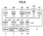
- main unit 1 a main unit of the laser printer 1 (hereinafter referred to as main unit 1) is connected with the host computer (the host device) 16 via an I/O interface 15 provided between the controller 2 and the host device 16 so as to form a communication system in which the main unit 1 and the host device 16 exchange requested data and control signals therebetween.
- the main unit 1 of the laser printer comprises the controller 2 performing an image processing, an image-formation engine 3, an engine control board 4 controlling the engine 3, and an operation panel 5 used for providing settings of various modes and an operation start instruction, etc.
- the controller 2, the image-formation engine 3 and the engine control board 4 exchange signals via an I/O interface (I/O) 6 of the engine control board 4.
- I/O I/O interface
- the engine 3 comprises a laser-writing unit 12 including an LD and a polygon motor, a sequencing unit group 13 conducting an engine sequence of a fixing system, a developing system and a driving system, and a sensor group 14 checking conditions on a paper path and conditions of the engine sequence.
- a laser-writing unit 12 including an LD and a polygon motor
- a sequencing unit group 13 conducting an engine sequence of a fixing system, a developing system and a driving system
- a sensor group 14 checking conditions on a paper path and conditions of the engine sequence.
- the engine control board 4 comprises a CPU 7, a RAM 8, a ROM 9, a nonvolatile memory (EEPROM) 10, and a dip switch (DIP-SW) 11.
- the CPU 7 controls the engine 3 as a whole according to programs stored in the program ROM 9, mode instructions from the operation panel 5, and commands from the controller 2 (and accompanying necessary information).
- the RAM 8 is used as a work memory of the CPU 7 or as an input buffer for input data.
- the ROM 9 stores the above-mentioned programs for controlling the engine 3.
- the nonvolatile memory (EEPROM) 10 stores information, such as error history of the engine 3 and contents of the mode instructions from the operation panel 5.
- the dip switch (DIP-SW) 11 is used for setting a mode of the engine control.
- the cooling-fan control of the present embodiment is performed in the CPU 7 controlling the engine 3.
- a CPU 201 controls the controller 2 as a whole according to programs stored in a programmable ROM (Prog.ROM) 204, the mode instructions from the operation panel 5, and commands from the host device 16.
- An IC card reader (IC Card) 202 is used for reading font data and programs from an IC card.
- a nonvolatile memory (NVRAM) 203 stores information, such as contents of the mode instructions from the operation panel 5.
- the programmable ROM 204 stores the above-mentioned programs for controlling the controller 2.
- a font ROM (Font.ROM) 205 stores data, such as font pattern data.
- a RAM 206 is used as a work memory of the CPU 201, as an input buffer for input data, as a page buffer for print data, or as a memory for download fonts. Additionally, a timer not shown in the figure measures a current time, and is utilized for measuring times, such as a conveying time of the transfer paper.
- An engine interface (Engine I/F) 207 communicates commands, statuses, and print data with the engine 3.
- the engine 3 has the above-described structure, and performs an actual printing.
- a panel interface (Panel I/F) 209 communicates commands and statuses with the operation panel 5.
- the operation panel 5 comprises a key group including a numeric keypad and a start key, and a display, such as an LCD, which are not shown in the figures.
- the operation panel 5 is used for informing a user of current conditions of the printer, and also is used by a user to provide the mode instructions.
- a host interface 211 enables a communication with the host device 16. Normally, the host interface 211 is formed by a Centronics interface or an RS232C, etc.
- the host device 16 hosts the laser printer 1, and includes a CPU, memories such as a RAM and a ROM, and an input-output device, which are not shown in the figures.
- a disk interface (DISK I/F) 213 enables a communication with a disk device (DISK) 214.
- the disk device 214 stores font data, programs, and various data, such as print data, and is formed by a floppy disk device or a hard disk device, etc.
- the controller 2 receives this print request, and informs the engine 3 of the print request.
- the engine 3 commences a paper-feeding operation, and further begins a printing operation.
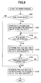
- the cooling fan 114 is started in operation (S101 in FIG.5).
- a resist sensor 103 shown in FIG.2
- a resist clutch (CL) is turned on for transmitting a driving force that revolves the resist roller 104 (YES in S102)
- the cooling fan is stopped revolving (S103).
- the cooling fan 114 is inhibited from generating an air current.
- the leading end of the transfer paper reaches the delivery sensor 112 such that the delivery sensor 112 turns on (YES in S104)
- the cooling fan 114 is restarted into operation (S105).
- the cooling fan 114 may be revolved at a lower velocity than a velocity at the start of feeding the transfer paper. Also, in place of restarting the cooling fan 114 after the leading end of the transfer paper reaches the delivery sensor 112, the revolving velocity of the cooling fan 114 may be returned to the velocity (a high velocity) at the start of feeding the transfer paper.
- FIG.6 shows a fan standby control performed after completion of the delivery of the transfer paper.
- a timer counting is started when the cooling fan 114 starts standing by (S201). Thereafter, when a predetermined time has elapsed (YES in S202), the cooling fan 114 is stopped (S203), and the timer counting is reset (S204).
- the image-forming device comprises the CPU 7 in the main unit 1 of the laser printer: upon feeding a transfer paper, the CPU 7 starts the cooling fan 114 or revolves the cooling fan 114 at a predetermined velocity; then, while the leading end of the transfer paper moves from the resist roller 104 to the delivery sensor 112 (in a period from the resist clutch (CL) being turned on to the delivery sensor 112 turning on), the CPU 7 stops the cooling fan 114 or revolves the cooling fan 114 at a lower velocity than a velocity at the start of feeding the transfer paper; and upon the delivery of the transfer paper, the CPU 7 restarts the cooling fan 114 or returns the revolving velocity of the cooling fan 114 to the velocity at the start of feeding the transfer paper.
- FIG.7 is a flowchart of a method for controlling the cooling fan according to a second embodiment of the present invention. It is noted that, since the present second embodiment has a similar structure to the structure of the above-described first embodiment, the following description will be given with reference also to FIG.2 to FIG.4, in which identical elements and steps are referred to by the same reference marks and numbers, and will not be described in detail.
- the difference of the present second embodiment from the first embodiment is as follows. Under the control of the CPU 7 in the main unit 1 of the laser printer, the cooling fan 114 is started upon feeding a transfer paper. Then, when the leading end of the transfer paper reaches the resist roller 104 (upon the resist clutch (CL) being turned on), the cooling fan 114 is stopped. Subsequently, a timing of the leading end of the transfer paper reaching the entrance of the fixing device 110 is calculated based on the distance (layout) from the resist roller 104 to the entrance of the fixing device 110 and a conveying velocity. According to this timing (after a predetermined time has elapsed), the cooling fan 114 is restarted.
- the timing of the leading end of the transfer paper reaching the entrance of the fixing device 110 can be calculated by using an existing conveyance control sensor (e.g., the resist sensor), and according to this timing, a position of the transfer paper being conveyed is estimated so as to control the start/stop or the revolving velocity of the cooling fan 114. This eliminates the above-mentioned inconveniences of blurred images or creases in the transfer paper without increasing sensors and costs involved.
- an existing conveyance control sensor e.g., the resist sensor
- a conveying time of the transfer paper is measured by the timer (mentioned in the first embodiment). Based on the result of this measurement, information detected by the sensor group 14, and a predetermined conveying velocity, a conveyed distance of the transfer paper is calculated so as to detect the timing of the leading end of the transfer paper reaching the entrance of the fixing device 110.
- the engine 3 commences a paper-feeding operation.
- the cooling fan 114 is started (S301 in FIG.7).
- the cooling fan is stopped revolving (S303).
- the cooling fan 114 is inhibited from generating an air current, and a timer counting is started (S304).
- a predetermined time has elapsed (YES in S305)
- the cooling fan 114 is restarted (S306).
- the above-mentioned time (used in S305) is preliminarily determined by calculating the timing of the leading end of the transfer paper reaching the entrance of the fixing device 110, based on the distance (layout) from the resist sensor 103 to the entrance of the fixing device 110 and the conveying velocity.
- the cooling fan 114 may be revolved at a lower velocity than a velocity at the start of feeding the transfer paper, and the revolving velocity of the cooling fan 114 may be returned to the velocity at the start of feeding the transfer paper when the predetermined time has elapsed.
- the transfer paper is conveyed through while the start/restart or the revolving velocity of the cooling fan 114 is controlled according to a distance of the transfer paper being conveyed from a predetermined position (e.g., a resist position).
- the fan standby control after completion of the delivery of the transfer paper is performed in the same manner as in the first embodiment shown in FIG.6, in which a timer counting is started after completion of the delivery of the transfer paper (S201), and thereafter, when a predetermined time has elapsed (YES in S202), the cooling fan 114 is stopped (S203), and the timer counting is reset (S204).
- FIG.8 is a flowchart of a method for controlling the cooling fan according to a third embodiment of the present invention. It is noted that, since the present third embodiment has a similar structure to the structure of the above-described first embodiment, the following description will be given with reference also to FIG.2 to FIG.4, in which identical elements and steps are referred to by the same reference marks and numbers, and will not be described in detail.
- the difference of the present third embodiment from the first embodiment is as follows. Under the control of the CPU 7 in the main unit 1 of the laser printer, the cooling fan 114 is started if another transfer paper (a second transfer paper) is not being conveyed between the resist sensor 103 and the delivery sensor 112 upon feeding a first transfer paper. If the second transfer paper is being conveyed therebetween, the cooling fan 114 is stopped revolving while the leading end of the second transfer paper moves from the resist roller 104 to the delivery sensor 112 (in a period from the resist clutch (CL) being turned on to the delivery sensor 112 turning on).
- a second transfer paper another transfer paper
- the cooling fan 114 is restarted.
- the cooling fan 114 is exclusively controlled in consideration to a transfer paper being conveyed between the transferring device and the fixing device when a plurality of transfer papers are being conveyed through the laser printer 1. This eliminates the above-mentioned inconveniences of blurred images or creases in the transfer paper, even when a continuous printing is performed.
- the CPU 7 in the laser printer 1 performs multitask/multithread operations, and executes from feeding to delivering of one transfer paper as one process. Therefore, when a plurality of transfer papers exist in the device, one process shown in FIG.8 is executed concurrently with other processes shown in FIG.8. For example, when a process regarding a preceding transfer paper A performs a thread of step S401 shown in FIG.8, a process regarding a following transfer paper B can perform a thread of the step S401.
- the engine 3 When a print request is transmitted from the host device 16 to the laser printer 1, the engine 3 starts feeding a transfer paper.
- the cooling fan 114 is started (S402). Then, when the leading end of the present transfer paper is detected by the resist sensor 103 such that the resist clutch (CL) is turned on (YES in S403), the cooling fan is stopped revolving (S404). Thus, the cooling fan 114 is inhibited from generating an air current.
- the cooling fan 114 may be revolved at a lower velocity than a velocity at the start of feeding the transfer paper. Also in place of restarting the cooling fan 114, the revolving velocity of the cooling fan 114 may be returned to the velocity (a high velocity) at the start of feeding the transfer paper.
- the transfer paper is conveyed through while the start/restart or the revolving velocity of the cooling fan 114 is controlled according to a position (a distance from the resist position) of the transfer paper being conveyed and whether or not the leading end of another transfer paper exists between the resist sensor 103 and the entrance of the fixing device 110.
- the fan standby control after completion of the delivery of the transfer paper is performed in the same manner as in the first embodiment shown in FIG.6, in which a timer counting is started after completion of the delivery of the transfer paper (S201), and thereafter, when a predetermined time has elapsed (YES in S202), the cooling fan 114 is stopped (S203), and the timer counting is reset (S204).
- FIG.9 is a flowchart of a method for controlling the cooling fan according to a fourth embodiment of the present invention. It is noted that, since the present fourth embodiment has a similar structure to the structure of the above-described first embodiment, the following description will be given with reference also to FIG.2 to FIG.4, in which identical elements and steps are referred to by the same reference marks and numbers, and will not be described in detail.
- a thin-paper mode is set via the operation panel 5 (or from the host device 16) so as to use a transfer paper thinner than a predetermined thickness, and the CPU 7 controls the cooling fan 114 in a similar manner to the above-described first embodiment in the thin-paper mode.
- This structure can eliminate the above-mentioned inconveniences of blurred images or creases in the transfer paper, while preventing the reduction of cooling effects of the cooling fan in a predetermined period from the transferring process to the fixing process, only when using a transfer paper thinner than a predetermined thickness.
- the above-mentioned thin-paper mode for using a transfer paper thinner than a predetermined thickness or a normal mode for using a transfer paper (a normal transfer paper) equal to or thicker than the predetermined thickness can be set by means of a key operation of the operation panel 5, etc.
- the setting is sent to the controller 2, and is stored updatably in the nonvolatile memory (NVRAM) 203.
- NVRAM nonvolatile memory
- the CPU 7 controls the cooling fan 114 in a predetermined period from the transferring of an image to a transfer paper to the fixing thereof such that the CPU 7 stops the cooling fan 114 or revolves the cooling fan 114 at a lower velocity than a velocity at the start of feeding the transfer paper, and upon the delivery of the transfer paper, the CPU 7 restarts the cooling fan 114 or returns the revolving velocity of the cooling fan 114 to the velocity at the start of feeding the transfer paper.
- the controller 2 receives this print request, and informs the engine 3 of the print request according to a mode set in the nonvolatile memory (NVRAM) 203. Thereby, the engine 3 commences a paper-feeding operation, and further begins a printing operation.
- the cooling fan 114 is started in operation (S101).
- the resist sensor 103 such that the resist clutch (CL) is turned on (YES in S102)
- the cooling fan is stopped revolving (S103).
- the cooling fan 114 is inhibited from generating an air current. Thereafter, when the leading end of the transfer paper reaches the delivery sensor 112 such that the delivery sensor 112 turns on (YES in S104), the cooling fan 114 is restarted into operation (S105). On the other hand, in the normal mode (NO in S501), the cooling fan 114 is continuously driven from the start of the feeding of the transfer paper to the completion of the delivery of the transfer paper (S105).
- the cooling fan 114 may be revolved at a lower velocity than a velocity at the start of feeding the transfer paper. Also, in place of restarting the cooling fan 114 after the transfer paper reaches the delivery sensor 112, the revolving velocity of the cooling fan 114 may be returned to the velocity at the start of feeding the transfer paper. Additionally, in the normal mode, the revolving velocity of the cooling fan 114 at the start of feeding the transfer paper may be maintained until the completion of the delivery of the transfer paper.
- the transfer paper is conveyed through the laser printer 1, while the start/restart or the revolving velocity of the cooling fan 114 is controlled according to a position of the transfer paper being conveyed, only in the thin-paper mode using a transfer paper thinner than in the normal mode.
- the fan standby control after completion of the delivery of the transfer paper is performed in the same manner as in the first embodiment shown in FIG.6, in which a timer counting is started after completion of the delivery of the transfer paper (S201), and thereafter, when a predetermined time has elapsed (YES in S202), the cooling fan 114 is stopped (S203), and the timer counting is reset (S204).
- the present embodiment is not limited to the above-described example.
- the setting of the thin-paper/normal mode may be performed on the host side, and the mode information may be included in the print request transmitted from the host device 16 to the laser printer 1.
- the host device 16 comprises at least an operation/display unit (e.g., an input device, such as a keyboard, and an output device, such as a CRT) used to set the thin-paper/normal mode, and a nonvolatile memory (e.g., an NVRAM) updatably storing the setting of the mode.
- an operation/display unit e.g., an input device, such as a keyboard, and an output device, such as a CRT
- NVRAM nonvolatile memory
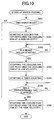
- FIG.10 is a flowchart of a method for controlling the cooling fan according to a fifth embodiment of the present invention. It is noted that, since the present fifth embodiment has a similar structure to the structure of the above-described first embodiment, the following description will be given with reference also to FIG.2 to FIG.4, in which identical elements and steps are referred to by the same reference marks and numbers, and will not be described in detail.
- the difference of the present fifth embodiment from the first embodiment is as follows.
- the thin-paper mode is set via the operation panel 5, etc., and the CPU 7 controls the cooling fan 114 in a similar manner to the above-described second embodiment, in the thin-paper mode.
- the timing of the leading end of the transfer paper reaching the entrance of the fixing device 110 is calculated by using the existing resist sensor, etc., and according to this timing, a position of the transfer paper being conveyed is estimated so as to control the start/stop or the revolving velocity of the cooling fan 114. This eliminates the above-mentioned inconveniences of blurred images or creases in the transfer paper without increasing sensors and costs involved, when using a transfer paper thinner than a predetermined thickness.
- a conveying time of the transfer paper is measured by the timer (mentioned in the first embodiment) of the laser printer 1. Based on the result of this measurement, information detected by the sensor group 14, and a predetermined conveying velocity, a conveyed distance of the transfer paper is calculated so as to detect the timing of the leading end of the transfer paper reaching the entrance of the fixing device 110.
- the above-mentioned thin-paper mode for using a transfer paper thinner than a predetermined thickness or the above-mentioned normal mode for using a normal transfer paper equal to or thicker than the predetermined thickness is set by means of a key operation via the operation panel 5, etc.
- This setting is sent to the controller 2, and is stored updatably in the nonvolatile memory (NVRAM) 203.
- the CPU 7 estimates a position of the transfer paper being conveyed according to the above-mentioned detected information and the result of the measurement by the above-mentioned timer, and controls the start/stop or the revolving velocity of the cooling fan 114 in a predetermined period from the transferring of an image to the transfer paper to the fixing thereof.
- the controller 2 receives this print request, and informs the engine 3 of the print request according to a mode set in the nonvolatile memory (NVRAM) 203. Thereby, the engine 3 commences a paper-feeding operation, and further begins a printing operation.
- the cooling fan 114 is started in operation (S301). Then, when the leading end of the transfer paper fed from the main feed device 101 is detected by the resist sensor 103 such that the resist clutch (CL) is turned on (YES in S302), the cooling fan is stopped revolving (S303).
- the cooling fan 114 is inhibited from generating an air current, and a timer counting is started (S304). Thereafter, when a predetermined time has elapsed (YES in S305), the cooling fan 114 is restarted (S306).
- the above-mentioned time (used in S305) is preliminarily determined by calculating the timing of the leading end of the transfer paper reaching the entrance of the fixing device 110, based on the distance (layout) from the resist sensor 103 to the entrance of the fixing device 110 and the conveying velocity.
- the cooling fan 114 is continuously driven from the start of the feeding of the transfer paper to the completion of the delivery of the transfer paper (S306).
- the cooling fan 114 may be revolved at a lower velocity than a velocity at the start of feeding the transfer paper, and the revolving velocity of the cooling fan 114 may be returned to the velocity at the start of feeding the transfer paper when the predetermined time has elapsed. Additionally, in the normal mode, the revolving velocity of the cooling fan 114 at the start of feeding the transfer paper may be maintained until the completion of the delivery of the transfer paper.
- the transfer paper is conveyed through the laser printer 1, while the start/restart or the revolving velocity of the cooling fan 114 is controlled according to a distance of the transfer paper being conveyed from a predetermined position (e.g., the resist position), only in the thin-paper mode using a transfer paper thinner than in the normal mode.
- the fan standby control after completion of the delivery of the transfer paper is performed in the same manner as in the first embodiment shown in FIG.6, in which a timer counting is started after completion of the delivery of the transfer paper (S201), and thereafter, when a predetermined time has elapsed (YES in S202), the cooling fan 114 is stopped (S203), and the timer counting is reset (S204).
- the present embodiment is not limited to the above-described example.
- the setting of the thin-paper/normal mode may be performed on the host side, and the mode information may be included in the print request transmitted from the host device 16 to the laser printer 1.
- the host device 16 comprises at least an operation/display unit (e.g., an input device, such as a keyboard, and an output device, such as a CRT) used to set the thin-paper/normal mode, and a nonvolatile memory (e.g., an NVRAM) updatably storing the setting of the mode.
- an operation/display unit e.g., an input device, such as a keyboard, and an output device, such as a CRT
- NVRAM nonvolatile memory
- FIG.11 is a flowchart of a method for controlling the cooling fan according to a sixth embodiment of the present invention. It is noted that, since the present sixth embodiment has a similar structure to the structure of the above-described first embodiment, the following description will be given with reference also to FIG.2 to FIG.4, in which identical elements and steps are referred to by the same reference marks and numbers, and will not be described in detail.
- the difference of the present sixth embodiment from the first embodiment is as follows.
- the thin-paper mode is set via the operation panel 5, etc., and the CPU 7 controls the cooling fan 114 in a similar manner to the above-described third embodiment, in the thin-paper mode.
- the cooling fan 114 is exclusively controlled in consideration to a transfer paper being conveyed between the transferring device and the fixing device when a plurality of transfer papers are being conveyed through the laser printer 1. This eliminates the above-mentioned inconveniences of blurred images or creases in the transfer paper, even when a continuous printing is performed.
- the above-mentioned thin-paper mode for using a transfer paper thinner than a predetermined thickness or the above-mentioned normal mode for using a normal transfer paper equal to or thicker than the predetermined thickness is set by means of a key operation via the operation panel 5 of the laser printer 1, etc. This setting is sent to the controller 2, and is stored updatably in the nonvolatile memory (NVRAM) 203.
- the CPU 7 estimates a position of the transfer paper being conveyed according to information detected by the sensors, and controls the start/restart or the revolving velocity of the cooling fan 114 in a predetermined period from the transferring of an image to the transfer paper to the fixing thereof. Additionally, when a plurality of transfer papers are being conveyed through the laser printer 1, the CPU 7 controls the cooling fan 114 exclusively in consideration to a transfer paper being conveyed between the transferring device and the fixing device.
- the CPU 7 in the laser printer 1 performs multitask/multithread operations, and executes from feeding to delivering of one transfer paper as one process. Therefore, when a plurality of transfer papers exist in the device, one process shown in FIG.11 is executed concurrently with other processes shown in FIG.11.
- the controller 2 receives this print request, and informs the engine 3 of the print request according to a mode set in the nonvolatile memory (NVRAM) 203. Thereby, the engine 3 commences a paper-feeding operation, and further begins a printing operation.
- the cooling fan 114 is started (S402). Then, when the leading end of the present transfer paper is detected by the resist sensor 103 such that the resist clutch (CL) is turned on (YES in S403), the cooling fan is stopped revolving (S404).
- the cooling fan 114 is inhibited from generating an air current. Thereafter, when the leading end of the transfer paper reaches the delivery sensor 112 such that the delivery sensor 112 turns on (YES in S405), and further when another transfer paper is not being conveyed between the resist sensor 103 and the entrance of the fixing device 110 (NO in S406), the cooling fan 114 is restarted into operation (S407).
- the cooling fan 114 is continuously driven from the start of the feeding of the transfer paper to the completion of the delivery of the transfer paper (S407).
- the cooling fan 114 may be revolved at a lower velocity than a velocity at the start of feeding the transfer paper. Also in place of restarting the cooling fan 114, the revolving velocity of the cooling fan 114 may be returned to the velocity at the start of feeding the transfer paper. Additionally, in the normal mode, the revolving velocity of the cooling fan 114 at the start of feeding the transfer paper may be maintained until the completion of the delivery of the transfer paper.
- the transfer paper is conveyed through the laser printer 1, while the start/restart or the revolving velocity of the cooling fan 114 is controlled according to a position (a distance from the resist position) of the transfer paper being conveyed and whether or not the leading end of another transfer paper exists between the resist sensor 103 and the entrance of the fixing device 110, only in the thin-paper mode using a transfer paper thinner than in the normal mode.
- the fan standby control after completion of the delivery of the transfer paper is performed in the same manner as in the first embodiment shown in FIG.6, in which a timer counting is started after completion of the delivery of the transfer paper (S201), and thereafter, when a predetermined time has elapsed (YES in S202), the cooling fan 114 is stopped (S203), and the timer counting is reset (S204).
- the present embodiment is not limited to the above-described example.
- the setting of the thin-paper/normal mode may be performed on the host side, and the mode information may be included in the print request transmitted from the host device 16 to the laser printer 1.
- the host device 16 comprises at least an operation/display unit (e.g., an input device, such as a keyboard, and an output device, such as a CRT) used to set the thin-paper/normal mode, and a nonvolatile memory (e.g., an NVRAM) updatably storing the setting of the mode.
- an operation/display unit e.g., an input device, such as a keyboard, and an output device, such as a CRT
- NVRAM nonvolatile memory
- FIG.12 is a flowchart of a method for controlling the cooling fan according to a seventh embodiment of the present invention.
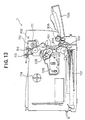
- FIG.13 is a cross-sectional view of an electrophotographic printer as an image-forming device according to the seventh embodiment of the present invention provided with a conveyance path. It is noted that, since the present seventh embodiment has a similar structure to the structure of the above-described first embodiment, the following description will be given with reference also to FIG.3 and FIG.4, in which identical elements and steps are referred to by the same reference marks and numbers, and will not be described in detail.
- the difference of the present seventh embodiment from the first embodiment is as follows.
- the laser printer 1 further comprises a temperature sensor 150, as shown in FIG.13.
- the thin-paper mode is set via the operation panel 5, etc.
- the temperature sensor 150 senses a temperature in the laser printer 1.
- the CPU 7 controls the cooling fan 114 in a similar manner to the above-described sixth embodiment. In this course, when the temperature in the laser printer 1 reaches a predetermined temperature, the CPU 7 starts the cooling fan 114, and halts the paper-feeding operation.
- the cooling fan 114 is started and the paper-feeding operation is inhibited. This not only eliminates the above-mentioned inconveniences of blurred images or creases in the transfer paper, but also maintains a proper temperature in the laser printer 1, when a plurality of transfer papers are being conveyed through the laser printer 1 in the thin-paper mode.
- the above-mentioned thin-paper mode for using a transfer paper thinner than a predetermined thickness or the above-mentioned normal mode for using a normal transfer paper equal to or thicker than the predetermined thickness is set by means of a key operation via the operation panel 5 of the laser printer 1, etc. This setting is sent to the controller 2, and is stored updatably in the nonvolatile memory (NVRAM) 203.
- the CPU 7 estimates a position of the transfer paper being conveyed according to information detected by the sensors, and controls the start/stop or the revolving velocity of the cooling fan 114 in a predetermined period from the transferring of an image to the transfer paper to the fixing thereof.
- the CPU 7 controls the cooling fan 114 exclusively in consideration to a transfer paper being conveyed between the transferring device and the fixing device.
- the CPU 7 restarts the cooling fan 114, and halts the paper-feeding operation.
- the temperature sensor 150 is included in the sensor group 14. The temperature sensor 150 senses an internal temperature of the laser printer 1, and informs the CPU 7 of the detected information (temperature information).
- the CPU 7 in the laser printer 1 according to the present seventh embodiment performs multitask/multithread operations, and executes from feeding to delivering of one transfer paper as one process. Therefore, when a plurality of transfer papers exist in the device, one process shown in FIG.12 is executed concurrently with other processes shown in FIG.12.
- the controller 2 receives this print request, and informs the engine 3 of the print request according to a mode set in the nonvolatile memory (NVRAM) 203. Thereby, the engine 3 commences a paper-feeding operation, and further begins a printing operation.
- the cooling fan 114 is started (S402). Then, when the leading end of the present transfer paper is detected by the resist sensor 103 such that the resist clutch (CL) is turned on (YES in S403), the cooling fan is stopped revolving (S404).
- the cooling fan 114 is inhibited from generating an air current. Thereafter, when the leading end of the transfer paper reaches the delivery sensor 112 such that the delivery sensor 112 turns on (YES in S405), and further when another transfer paper is not being conveyed between the resist sensor 103 and the entrance of the fixing device 110 (NO in S406), the cooling fan 114 is restarted into operation (S407).
- the cooling fan 114 is not started. Further, when the leading end of the transfer paper is detected by the delivery sensor 112 (YES in S405), and when another transfer paper is being conveyed between the resist sensor 103 and the entrance of the fixing device 110 (YES in S406), the controller 2 judges from the information detected by the temperature sensor 150 whether or not the temperature in the laser printer 1 is equal to or higher than a predetermined temperature (S801).
- the cooling fan 114 is started/restarted (S802), and the paper-feeding operation is inhibited (S803). Afterwards, when it is judged from the information detected by the temperature sensor 150 that the temperature in the laser printer 1 falls below the predetermined temperature (NO in S804), the inhibition of the paper-feeding operation is cancelled (S805).
- the cooling fan 114 is continuously driven from the start of the feeding of the transfer paper to the completion of the delivery of the transfer paper (S407).
- the cooling fan 114 may be revolved at a lower velocity than a velocity at the start of feeding the transfer paper. Also in place of restarting the cooling fan 114, the revolving velocity of the cooling fan 114 may be returned to the velocity at the start of feeding the transfer paper. Additionally, in the normal mode, the revolving velocity of the cooling fan 114 at the start of feeding the transfer paper may be maintained until the completion of the delivery of the transfer paper.
- the transfer paper is conveyed through the laser printer 1, while the start/restart or the revolving velocity of the cooling fan 114 is controlled according to a position (a distance from the resist position) of the transfer paper being conveyed, according to whether or not the leading end of another transfer paper exists between the resist sensor 103 and the entrance of the fixing device 110, and according to whether or not the temperature in the laser printer 1 is equal to or higher than a predetermined temperature, only in the thin-paper mode using a transfer paper thinner than in the normal mode.
- the fan standby control after completion of the delivery of the transfer paper is performed in the same manner as in the first embodiment shown in FIG.6, in which a timer counting is started after completion of the delivery of the transfer paper (S201), and thereafter, when a predetermined time has elapsed (YES in S202), the cooling fan 114 is stopped (S203), and the timer counting is reset (S204).
- halting the paper-feeding operation elongates paper-feeding intervals, and thus decreases the number of papers fed per unit time; however, revolving the cooling fan 114 while halting the paper-feeding operation can restore a proper temperature in the laser printer 1 before feeding the next transfer paper, achieving sufficient cooling effects.
- the present embodiment is not limited to the above-described example.
- the setting of the thin-paper/normal mode may be performed on the host side, and the mode information may be included in the print request transmitted from the host device 16 to the laser printer 1.
- the host device 16 comprises at least an operation/display unit (e.g., an input device, such as a keyboard, and an output device, such as a CRT) used to set the thin-paper/normal mode, and a nonvolatile memory (e.g., an NVRAM) updatably storing the setting of the mode.
- an operation/display unit e.g., an input device, such as a keyboard, and an output device, such as a CRT
- NVRAM nonvolatile memory
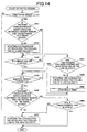
- FIG.14 is a flowchart of a method for controlling the cooling fan according to an eighth embodiment of the present invention. It is noted that, since the present eighth embodiment has a similar structure to the structure of the above-described first embodiment, the following description will be given with reference also to FIG.2 to FIG.4, in which identical elements and steps are referred to by the same reference marks and numbers, and will not be described in detail.
- the difference of the present eighth embodiment from the first embodiment is as follows.
- the thin-paper mode is set via the operation panel 5, etc.
- the CPU 7 controls the cooling fan 114 in a similar manner to the above-described sixth embodiment. In this course, when a predetermined time or more has elapsed since the cooling fan 114 has been stopped, the CPU 7 starts the cooling fan 114. This not only eliminates the above-mentioned inconveniences of blurred images or creases in the transfer paper, but also maintains a proper temperature in the laser printer 1 during a continuous printing in the thin-paper mode.
- the above-mentioned thin-paper mode for using a transfer paper thinner than a predetermined thickness or the above-mentioned normal mode for using a normal transfer paper equal to or thicker than the predetermined thickness is set by means of a key operation via the operation panel 5 of the laser printer 1, etc. This setting is sent to the controller 2, and is stored updatably in the nonvolatile memory (NVRAM) 203.
- the CPU 7 estimates a position of the transfer paper being conveyed according to information detected by the sensors, and controls the start/restart or the revolving velocity of the cooling fan 114 in a predetermined period from the transferring of an image to the transfer paper to the fixing thereof.
- the CPU 7 controls the cooling fan 114 exclusively in consideration to a transfer paper being conveyed between the transferring device and the fixing device. In this course, when a predetermined time or more has elapsed since the cooling fan 114 has been stopped, the CPU 7 forcibly restarts the cooling fan 114.
- the CPU 7 in the laser printer 1 according to the present eighth embodiment performs multitask/multithread operations, and executes from feeding to delivering of one transfer paper as one process. Therefore, when a plurality of transfer papers exist in the device, one process shown in FIG.14 is executed concurrently with other processes shown in FIG.14.
- the controller 2 receives this print request, and informs the engine 3 of the print request according to a mode set in the nonvolatile memory (NVRAM) 203. Thereby, the engine 3 commences a paper-feeding operation, and further begins a printing operation.
- the cooling fan 114 is started (S402). Then, when the leading end of the present transfer paper is detected by the resist sensor 103 such that the resist clutch (CL) is turned on (YES in S403), the cooling fan is stopped revolving (S404).
- the cooling fan 114 is inhibited from generating an air current. Thereafter, when the leading end of the transfer paper reaches the delivery sensor 112 such that the delivery sensor 112 turns on (YES in S405), and further when another transfer paper is not being conveyed between the resist sensor 103 and the entrance of the fixing device 110 (NO in S406), the cooling fan 114 is restarted into operation (S407).
- the cooling fan 114 is not started. Additionally, when the leading end of the present transfer paper is detected by the resist sensor 103 such that the resist clutch (CL) is turned on (YES in S403), it is judged whether or not the cooling fan 114 has been stopped (S901). When the cooling fan 114 has not been stopped (No in S901), the cooling fan 114 is stopped (S404), and then the timer (mentioned in the first embodiment) is started (S902).
- the cooling fan 114 is continuously driven from the start of the feeding of the transfer paper to the completion of the delivery of the transfer paper (S407).
- the cooling fan 114 may be revolved at a lower velocity than a velocity at the start of feeding the transfer paper. Also in place of restarting the cooling fan 114, the revolving velocity of the cooling fan 114 may be returned to the (high) velocity at the start of feeding the transfer paper. Additionally, in the normal mode, the revolving velocity of the cooling fan 114 at the start of feeding the transfer paper may be maintained until the completion of the delivery of the transfer paper.
- the transfer paper is conveyed through the laser printer 1, while the start/restart or the revolving velocity of the cooling fan 114 is controlled according to a position (a distance from the resist position) of the transfer paper being conveyed, according to whether or not the leading end of another transfer paper exists between the resist sensor 103 and the entrance of the fixing device 110, and according to whether or not the predetermined time has elapsed, only in the thin-paper mode using a transfer paper thinner than in the normal mode.
- the fan standby control after completion of the delivery of the transfer paper is performed in the same manner as in the first embodiment shown in FIG.6, in which a timer counting is started after completion of the delivery of the transfer paper (S201), and thereafter, when a predetermined time has elapsed (YES in S202), the cooling fan 114 is stopped (S203), and the timer counting is reset (S204).
- a timer counting is started after completion of the delivery of the transfer paper (S201), and thereafter, when a predetermined time has elapsed (YES in S202), the cooling fan 114 is stopped (S203), and the timer counting is reset (S204).
- the present embodiment is not limited to the above-described example.
- the setting of the thin-paper/normal mode may be performed on the host side, and the mode information may be included in the print request transmitted from the host device 16 to the laser printer 1.
- the host device 16 comprises at least an operation/display unit (e.g., an input device, such as a keyboard, and an output device, such as a CRT) used to set the thin-paper/normal mode, and a nonvolatile memory (e.g., an NVRAM) updatably storing the setting of the mode.
- an operation/display unit e.g., an input device, such as a keyboard, and an output device, such as a CRT
- NVRAM nonvolatile memory
- the cooling fan 114 when the predetermined time has elapsed (YES in S903), the cooling fan 114 is restarted into operation, or the revolving velocity of the cooling fan 114 is returned to the high velocity (S407), as described above, and thereafter, when another predetermined time has elapsed in the controller 2, the cooling fan 114 may be stopped again or revolved at the lower velocity.
- This method can eliminate the above-mentioned inconveniences of blurred images or creases in the transfer paper, while maintaining a proper temperature in the laser printer 1 during a continuous printing in the thin-paper mode.
- the control (the method for controlling the cooling fan) according to each of the above-mentioned embodiments is performed by the CPU 7 controlling the engine 3. Accordingly, programs downloaded form networks (such as a public network, a LAN, and the Internet) and programs read from a recording media such as a CD-ROM and an IC card are written to the above-mentioned ROM 9 storing programs for controlling the engine 3.
- the ROM 9 needs to be formed by an electrically erasable and rewritable element, such as a flash memory.
- an IC card storing programs is inserted into the IC card reader 202, and the programs read therefrom may be written to the ROM 9 for the engine 3 via the engine interface 207.
- the timing to control the start/stop or the revolving velocity of the cooling fan 114 is detected according to information detected by the resist sensor 103 and the delivery sensor 112 in a period including at least the interval from the exit of the transferring device comprising the transfer roller 107 and the photosensitive member 108 to the entrance of the fixing device 110.
- the present invention is not limited to the above-described embodiments, and other sensors can be substituted for the sensors 103 and 112.
- another sensor may be newly provided between the resist roller 104 and the transfer roller 107. In this structure, the newly provided sensor can detect a transfer paper at a position nearer to the transfer roller 107 than the resist sensor 103 does.
- the timing to control the start/stop or the revolving velocity of the cooling fan 114 may be detected according to an electromagnetic clutch (the resist clutch) provided on a driving axle of the resist roller 104 turning on or off. This method can stop the cooling fan 114 or revolve the cooling fan 114 at a lower velocity, immediately after the transferring, so as to keep the reduction of cooling effects as little as possible.
- At least the transfer roller 107 and the photosensitive member 108 form transferring means.
- At least the fixing device 110 forms fixing means.
- At least the main feed device 101 and the resist roller 104 form feeding means.
- At least the resist sensor 103 and the delivery sensor 112 form conveyance-position detecting means.
- At least the controller 2 and the CPU 7 form controlling means.
- At least the above-mentioned timer forms timing means.
- At least the operation panel 5 (or the operation/display unit of the host device 16) forms mode-setting means.
- At least the temperature sensor 150 forms temperature-sensing means.
- the revolving condition of the cooling fan is controlled in accordance with the conveyance position of the transfer sheet as detected by the conveyance-position detecting means.
Landscapes
- Physics & Mathematics (AREA)
- General Physics & Mathematics (AREA)
- Life Sciences & Earth Sciences (AREA)
- Engineering & Computer Science (AREA)
- Atmospheric Sciences (AREA)
- Biodiversity & Conservation Biology (AREA)
- Ecology (AREA)
- Environmental & Geological Engineering (AREA)
- Environmental Sciences (AREA)
- Control Or Security For Electrophotography (AREA)
- Fixing For Electrophotography (AREA)
- Accessory Devices And Overall Control Thereof (AREA)
Applications Claiming Priority (4)
| Application Number | Priority Date | Filing Date | Title |
|---|---|---|---|
| JP2000399947 | 2000-12-28 | ||
| JP2000399947 | 2000-12-28 | ||
| JP2001054726 | 2001-02-28 | ||
| JP2001054726A JP2002258722A (ja) | 2000-12-28 | 2001-02-28 | 画像形成装置、記録媒体、ならびにプログラム |
Publications (2)
| Publication Number | Publication Date |
|---|---|
| EP1220053A2 true EP1220053A2 (de) | 2002-07-03 |
| EP1220053A3 EP1220053A3 (de) | 2002-12-11 |
Family
ID=26606991
Family Applications (1)
| Application Number | Title | Priority Date | Filing Date |
|---|---|---|---|
| EP01130620A Withdrawn EP1220053A3 (de) | 2000-12-28 | 2001-12-27 | Bilderzeugungsgerät und Verfahren zur Steuerung eines Kühlgebläses |
Country Status (3)
| Country | Link |
|---|---|
| US (1) | US6580884B2 (de) |
| EP (1) | EP1220053A3 (de) |
| JP (1) | JP2002258722A (de) |
Cited By (3)
| Publication number | Priority date | Publication date | Assignee | Title |
|---|---|---|---|---|
| EP1467260A1 (de) * | 2003-04-07 | 2004-10-13 | Canon Kabushiki Kaisha | Fehlerbezogene Lüftersteuerung für einen Bildformungsapparat |
| EP1826630A1 (de) * | 2006-02-24 | 2007-08-29 | Samsung Electronics Co., Ltd. | Vorrichtung und Verfahren zur Steuerung einer Fixiereinheit |
| WO2009080060A1 (en) * | 2007-12-19 | 2009-07-02 | Nokia Corporation | Improved cooling arrangement, device and method |
Families Citing this family (17)
| Publication number | Priority date | Publication date | Assignee | Title |
|---|---|---|---|---|
| JP4031416B2 (ja) * | 2002-09-05 | 2008-01-09 | 株式会社リコー | ファイル転送システム、ファイル管理サーバ、ファイル転送方法、その方法をコンピュータが実行するためのプログラム、画像形成システム、蓄積文書管理サーバおよび画像形成装置 |
| DE10246394B4 (de) * | 2002-10-04 | 2007-03-08 | Eastman Kodak Co. | Fixiereinrichtung und Fixierverfahren für eine Druckmaschine |
| DE20302484U1 (de) * | 2003-01-23 | 2003-09-04 | Elitegroup Computer Systems Co., Ltd., Taipeh/T'ai-pei | Bedienungsfeld zum Einstellen der Betriebsfrequenz eines Computers und zum Anzeigen von Systeminformationen |
| JP4892871B2 (ja) * | 2005-05-27 | 2012-03-07 | コニカミノルタビジネステクノロジーズ株式会社 | 画像形成装置 |
| JP2007041025A (ja) * | 2005-07-29 | 2007-02-15 | Canon Inc | 定着装置および画像形成装置 |
| JP4794952B2 (ja) * | 2005-09-05 | 2011-10-19 | キヤノン株式会社 | 画像形成装置及びその制御方法 |
| JP2007219192A (ja) * | 2006-02-17 | 2007-08-30 | Seiko Epson Corp | 画像形成装置およびその冷却制御方法 |
| JP4717745B2 (ja) | 2006-08-03 | 2011-07-06 | キヤノン株式会社 | シート搬送装置及び画像形成装置 |
| JP5151520B2 (ja) * | 2008-02-08 | 2013-02-27 | コニカミノルタビジネステクノロジーズ株式会社 | 画像形成装置 |
| JP2009265154A (ja) | 2008-04-22 | 2009-11-12 | Sharp Corp | 画像形成装置、画像形成装置における印刷方法および画像形成装置における印刷処理を機能させるコンピュータプログラム |
| US8682202B2 (en) * | 2010-06-17 | 2014-03-25 | Kabushiki Kaisha Toshiba | Image forming apparatus that includes operation control unit controlling a plurality of fans for discharging ozone and a fixing device |
| JP5888905B2 (ja) * | 2011-09-01 | 2016-03-22 | キヤノン株式会社 | 画像形成装置 |
| JP5904746B2 (ja) * | 2011-10-13 | 2016-04-20 | キヤノン株式会社 | 画像形成装置 |
| JP2015125429A (ja) * | 2013-12-27 | 2015-07-06 | キヤノン株式会社 | 画像形成装置、画像形成装置の制御方法、及びプログラム |
| JP6063885B2 (ja) * | 2014-02-28 | 2017-01-18 | 京セラドキュメントソリューションズ株式会社 | 画像形成装置 |
| JP2020034863A (ja) * | 2018-08-31 | 2020-03-05 | キヤノン株式会社 | 画像形成装置 |
| JP7618394B2 (ja) * | 2020-05-28 | 2025-01-21 | キヤノン株式会社 | 画像形成装置 |
Family Cites Families (10)
| Publication number | Priority date | Publication date | Assignee | Title |
|---|---|---|---|---|
| JPS60122657A (ja) * | 1983-12-06 | 1985-07-01 | Canon Inc | 搬送装置 |
| JPH01316757A (ja) | 1988-06-17 | 1989-12-21 | Canon Inc | 画像形成装置 |
| JPH04134459A (ja) | 1990-09-27 | 1992-05-08 | Canon Inc | 画像形成装置の冷却装置 |
| JPH05216320A (ja) * | 1992-02-05 | 1993-08-27 | Ricoh Co Ltd | 電子写真装置 |
| JPH07319370A (ja) | 1994-05-30 | 1995-12-08 | Ricoh Co Ltd | 画像形成装置 |
| JPH0830183A (ja) | 1994-07-16 | 1996-02-02 | Ricoh Co Ltd | 画像形成装置 |
| JPH0962139A (ja) * | 1995-08-25 | 1997-03-07 | Ricoh Co Ltd | カラー画像形成装置 |
| JPH10207326A (ja) * | 1997-01-16 | 1998-08-07 | Canon Inc | 画像形成装置 |
| KR100306746B1 (ko) * | 1998-12-19 | 2002-03-21 | 윤종용 | 전자사진현상기의팬구동제어방법 |
| JP2002040873A (ja) * | 2000-05-19 | 2002-02-06 | Ricoh Co Ltd | 画像形成装置 |
-
2001
- 2001-02-28 JP JP2001054726A patent/JP2002258722A/ja active Pending
- 2001-12-27 EP EP01130620A patent/EP1220053A3/de not_active Withdrawn
- 2001-12-27 US US10/026,684 patent/US6580884B2/en not_active Expired - Lifetime
Non-Patent Citations (1)
| Title |
|---|
| None * |
Cited By (5)
| Publication number | Priority date | Publication date | Assignee | Title |
|---|---|---|---|---|
| EP1467260A1 (de) * | 2003-04-07 | 2004-10-13 | Canon Kabushiki Kaisha | Fehlerbezogene Lüftersteuerung für einen Bildformungsapparat |
| US6985677B2 (en) | 2003-04-07 | 2006-01-10 | Canon Kabushiki Kaisha | Image formation apparatus |
| EP1826630A1 (de) * | 2006-02-24 | 2007-08-29 | Samsung Electronics Co., Ltd. | Vorrichtung und Verfahren zur Steuerung einer Fixiereinheit |
| CN102226872A (zh) * | 2006-02-24 | 2011-10-26 | 三星电子株式会社 | 用于控制定影单元的设备和方法 |
| WO2009080060A1 (en) * | 2007-12-19 | 2009-07-02 | Nokia Corporation | Improved cooling arrangement, device and method |
Also Published As
| Publication number | Publication date |
|---|---|
| US6580884B2 (en) | 2003-06-17 |
| US20020085856A1 (en) | 2002-07-04 |
| EP1220053A3 (de) | 2002-12-11 |
| JP2002258722A (ja) | 2002-09-11 |
Similar Documents
| Publication | Publication Date | Title |
|---|---|---|
| US6580884B2 (en) | Image-forming device controlling a cooling fan according to a position of a transfer sheet being conveyed | |
| US9285767B2 (en) | Image forming apparatus | |
| CN101086636B (zh) | 图像形成设备和输送故障判断方法 | |
| KR100418045B1 (ko) | 화상형성장치 | |
| JP2003095482A (ja) | 画像形成装置 | |
| US9210286B2 (en) | Printing apparatus capable of reducing time required for continuous printing and printing control method | |
| JP2003271010A (ja) | 画像形成装置及び定着温度制御方法 | |
| JP2002154682A (ja) | 画像形成装置 | |
| US10520873B2 (en) | Image forming apparatus and image forming method | |
| JP2003122071A (ja) | 画像形成装置 | |
| JP4627191B2 (ja) | 画像形成装置 | |
| JP2007003992A (ja) | 画像形成装置 | |
| JP2002132087A (ja) | 画像形成装置 | |
| JP2006017988A (ja) | 画像形成装置 | |
| US7212754B2 (en) | Image forming apparatus forming an image by thermally fixing a developed image | |
| JP3858722B2 (ja) | 画像形成装置 | |
| JP2001348129A (ja) | 給紙装置及び画像形成装置 | |
| JPH11100135A (ja) | シート搬送装置及び画像形成装置 | |
| JP2005091556A (ja) | 画像形成装置および画像形成方法 | |
| JP2003005570A (ja) | 画像形成装置 | |
| US20070177002A1 (en) | Auto registration image forming apparatus | |
| US20070217853A1 (en) | Imaging apparatus and imaging method | |
| JP6922363B2 (ja) | 画像形成制御装置、画像形成制御方法及び画像形成装置 | |
| JP2007017691A (ja) | 画像形成装置 | |
| JPH1020734A (ja) | 画像形成装置 |
Legal Events
| Date | Code | Title | Description |
|---|---|---|---|
| PUAI | Public reference made under article 153(3) epc to a published international application that has entered the european phase |
Free format text: ORIGINAL CODE: 0009012 |
|
| 17P | Request for examination filed |
Effective date: 20011227 |
|
| AK | Designated contracting states |
Kind code of ref document: A2 Designated state(s): AT BE CH CY DE DK ES FI FR GB GR IE IT LI LU MC NL PT SE TR |
|
| AX | Request for extension of the european patent |
Free format text: AL;LT;LV;MK;RO;SI |
|
| PUAL | Search report despatched |
Free format text: ORIGINAL CODE: 0009013 |
|
| AK | Designated contracting states |
Kind code of ref document: A3 Designated state(s): AT BE CH CY DE DK ES FI FR GB GR IE IT LI LU MC NL PT SE TR |
|
| AX | Request for extension of the european patent |
Free format text: AL;LT;LV;MK;RO;SI |
|
| AKX | Designation fees paid |
Designated state(s): DE FR GB |
|
| 17Q | First examination report despatched |
Effective date: 20061018 |
|
| STAA | Information on the status of an ep patent application or granted ep patent |
Free format text: STATUS: THE APPLICATION HAS BEEN WITHDRAWN |
|
| 18W | Application withdrawn |
Effective date: 20090525 |