EP1221430A2 - Procede de fabrication de preformes dotees avec du fluor pour fibres optiques - Google Patents
Procede de fabrication de preformes dotees avec du fluor pour fibres optiques Download PDFInfo
- Publication number
- EP1221430A2 EP1221430A2 EP01306909A EP01306909A EP1221430A2 EP 1221430 A2 EP1221430 A2 EP 1221430A2 EP 01306909 A EP01306909 A EP 01306909A EP 01306909 A EP01306909 A EP 01306909A EP 1221430 A2 EP1221430 A2 EP 1221430A2
- Authority
- EP
- European Patent Office
- Prior art keywords
- fluorine
- doping
- porous
- sif
- silica
- Prior art date
- Legal status (The legal status is an assumption and is not a legal conclusion. Google has not performed a legal analysis and makes no representation as to the accuracy of the status listed.)
- Granted
Links
Images


Classifications
-
- C—CHEMISTRY; METALLURGY
- C03—GLASS; MINERAL OR SLAG WOOL
- C03B—MANUFACTURE, SHAPING, OR SUPPLEMENTARY PROCESSES
- C03B37/00—Manufacture or treatment of flakes, fibres, or filaments from softened glass, minerals, or slags
- C03B37/01—Manufacture of glass fibres or filaments
- C03B37/012—Manufacture of preforms for drawing fibres or filaments
- C03B37/014—Manufacture of preforms for drawing fibres or filaments made entirely or partially by chemical means, e.g. vapour phase deposition of bulk porous glass either by outside vapour deposition [OVD], or by outside vapour phase oxidation [OVPO] or by vapour axial deposition [VAD]
- C03B37/01446—Thermal after-treatment of preforms, e.g. dehydrating, consolidating, sintering
-
- C—CHEMISTRY; METALLURGY
- C03—GLASS; MINERAL OR SLAG WOOL
- C03B—MANUFACTURE, SHAPING, OR SUPPLEMENTARY PROCESSES
- C03B2201/00—Type of glass produced
- C03B2201/06—Doped silica-based glasses
- C03B2201/08—Doped silica-based glasses doped with boron or fluorine or other refractive index decreasing dopant
- C03B2201/12—Doped silica-based glasses doped with boron or fluorine or other refractive index decreasing dopant doped with fluorine
Definitions
- This invention relates to methods for making depressed index optical fibers and is directed more specifically to techniques for preparing preforms prior to fiber draw.
- Depressed clad optical fibers were developed in the early 1980's as an alternative to fibers with doped cores and less heavily doped, or undoped cladding. See, e.g., U.S. Patent No. 4,439,007. Depressed cladding allows the use of fiber cores with relatively low doping, or no doping at all. These cores produce low optical loss.
- a fiber structure that meets this requirement is one with multiple claddings including one or more of down-doped silica.
- One technique for making depressed clad fibers is to dope the cladding of a silica core fiber with fluorine or boron, which produces cladding with a refractive index less than the silica core.
- fibers with negative refractive index variations, ⁇ n, in the range 0.05 - 0.7 % can be obtained using fluorine doping.
- fibers with down doped core regions which have a core shell doped with fluorine and a center region doped with a conventional dopant such as germania.
- Manufacture of these fibers typically involves a standard VAD process, but the process is complicated by the step of selectively doping the shell region with fluorine. Fluorine diffuses readily into the porous structure and it is difficult to prevent fluorine migration into the germania doped core region.
- Fibers with depressed index cores or cladding can be produced using any of the conventional optical fiber production techniques, which include rod in tube processes, MCVD and PCVD (inside tube deposition processes), and VAD or OVD (outside tube deposition processes).
- the rod-in-tube approach may be preferred due to the large amount of cladding material required.
- Preforms for these fibers require a high quality, low loss cladding tube.
- fluorine doped cladding a desirable option for preparing the fluorine doped cladding tube is by a sol-gel process. This process is described in detail in U.S. Patent No. 5,240,488, which is incorporated herein by reference for those process details.
- a porous silica tube is produced, and then heated to consolidate it into a solid (vitreous) cladding tube.
- the rod is then inserted and the tube collapsed around the rod.
- Depressed clad optical fiber preforms can also be made using vapor axial deposition (VAD), or outside vapor deposition (OVD).
- VAD vapor axial deposition
- OLED outside vapor deposition
- Each of these processes produces an intermediate product which is a shaped porous particulate material that is then consolidated into a preform.
- the common ingredient in all of these techniques is that, at one stage in the preform fabrication process, the preform is a highly porous silica body. Porosity of these bodies is typically in the range of 50-90%, measured as volume of the voids to total volume of the body.
- the porous silica body In the manufacture of fluorine doped preforms, it is convenient to dope the porous silica body with fluorine by "soaking" the cladding tube in a fluorine containing gas atmosphere with the cladding tube still in the porous state, i.e. prior to consolidation.
- the porosity of the cladding tube at this stage in the process allows the fluorine gas to easily permeate through the entire thickness of the wall of a cladding tube, and through the thickness of a core rod.
- the conventional practice is to diffuse fluorine into the silica body using an equilibrium doping process. In this process, the silica body is heated to a temperature of rapid diffusion, in the presence of a low partial pressure of fluorine, i.e.
- preform will refer to the final structure after consolidation or after assembly of the rod and tube, and collapse of the tube around the rod.
- the preform stage is the final fabrication stage of the glass prior to drawing the optical fiber.
- cladding tube refers to the glass tube into which the core glass rod is inserted to make a preform.
- the cladding tube may be referred to as porous, i.e. prior to consolidation, or simply a cladding tube which suggests that consolidation is complete and the tube is solid glass and ready for rod-in-tube assembly.
- the example used in this description is a cladding tube made by a sol-gel process. It will be understood that the invention applies equally to the manufacture of optical fibers using preforms made by any suitable technique that results in a porous body that is to be fluorine doped. As indicated earlier, these techniques include VAD, OVD, MCVD, etc. and the porous body may include both cladding tubes and core rods.
- a silica sol is prepared by dispersing a silica powder in water.
- the particulate comprising the powder typically has a surface area in the range of 10 to 200 m 2 /g.
- Examples of silica are various kinds of fumed silica sold under trade names Aerosil TM or Cab-O-Sil TM.
- Aerosil TM or Cab-O-Sil TM Alternatively, a commercially available silica sol may be used. Typical concentration levels in the sol are 30-70% by weight. A higher amount is beneficial, because it reduces shrinkage of the gel body.
- Other additives may be included in the silica sol, and to preserve the fluidity some additional water may be added to preserve approximately the same solid-to-water ratio as in the pure silica sol.
- the pH of the mixture is adjusted, using a water soluble base such as tetramethylammonium hydroxide (TMAH), to a pH level in the range 10-13, typically approximately 12.
- TMAH tetramethylam
- the above prepared sol was gelled by lowering the pH over several minutes by adding 0.5-2%, typically 1%, of methyl formate (MF) or another acid producing media.
- the pH target is approximately 9.
- the sol is cast into the space between two concentric steel tubes to form the porous cladding tube.
- the inside diameter of the outer silica tube fixes the approximate outside diameter of the porous cladding tube and the outside diameter of the inside steel rod or tube determines the inside diameter of the porous cladding tube.
- the final dimensions of the consolidated cladding tube will be determined by the shrinkage of the gel upon drying and further shrinkage of the porous cladding tube during consolidation. These dimensional changes are well known, very reproducable, and are taken into account when designing the sol gel mold.
- the dried porous cladding tube is heated slowly to a temperature above 600 °C and preferably approximately 1100 °C to burn out organic additives and to strengthen the material for further handling. At this point the tube has sufficient integrity to be handled but is still porous.
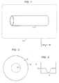
- the porous tube is then treated in a furnace 12, indicated schematically in Figure 1, and a fluorine gas atmosphere is introduced into the furnace to provide the fluorine dopant for the porous cladding tube.
- the usual fluorine source is SiF 4 with a carrier gas such as argon or helium.
- the furnace atmosphere is heated to a temperature in the range 500-1200 °C for this step.
- Molecular SiF 4 permeates into the body through both the inside bore and outside surface of the porous cladding tube, thus penetrating the entire thickness of the tube.
- diffusion of atomic fluorine begins at the particle surface. This effect is termed diffusion to define doping of the individual silica particles with elemental fluorine.
- the particle diffusion step is represented by Figure 2, which shows an individual silica particle 13 doped with fluorine 14.
- the diffusion front 15 proceeds from the surface of the particle, which is exposed to the fluorine atmosphere, to the center of the particle. As shown in Figure 2, the diffusion is incomplete.
- the concentration of fluorine as a function of distance toward the center of the particle is represented by Figure 3.
- the abscissa is the distance through the thickness of the particle and the ordinate is the concentration of fluorine C.
- the target concentration, for the desired index depression, is C T .
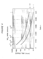
- ⁇ n is proportional to the SiF 4 partial pressure to the quarter power: (1) ⁇ n ⁇ P 1/4
- the doping time scale, t D can be defined by the ratio of the desired ⁇ n times the body mass divided by the SiF 4 partial pressure, SiF 4 mass, and the total flow, corrected by a doping efficiency, ⁇ , which is the fraction of SiF 4 incorporated in the sample to the total amount supplied.
- the doping time scale, t D is given by: (2) t D ⁇ ( ⁇ nW)/PFM)(1/ ⁇ ) ⁇ K ⁇ n/ ⁇ n 4 (1/ ⁇ ) ⁇ K ⁇ n -3 (1/ ⁇ ) ; K ⁇ W/(FM) where M and P are the molecular weight of SiF 4 and the partial pressure, respectively.
- Equation 2 shows that for a given sample size and SiF 4 flow rate, the doping time scale t D is proportional to ⁇ n -3 .
- the doping process in this regime is expected to be limited by diffusion in the porous body, further decreasing doping efficiencies.
- ⁇ n 0.001 - 0.003
- the doping process clearly becomes very time consuming due to the low rate of SiF 4 introduction into the reaction vessel.
- a fundamentally different doping approach is used.
- a high SiF 4 partial pressure, well above the equilibrium partial pressure, is used to predeposit excess fluorine as a surface layer on the particles of the porous body.
- this predeposition step may be carried out at a temperature below the effective diffusion temperature for practical distribution of fluorine throughout the silica particles, i.e. 1000 °C or below.
- a range of 800-1000 °C is recommended.
- the fluorine deposits on the particle surface mainly by molecular absorption, which is essentially instantaneous compared with the time required for fluorine to penetrate substantially into the particle by atomic diffusion.
- the total amount of fluorine required for the index modification of the preform is deposited as a concentrated surface layer in a relatively short doping step.
- This deposition of excess fluorine on the surface of the particles of the porous body is the first stage of the incremental doping process.
- the porous body is removed from the fluorine doping atmosphere (or decreased to equilibrium for ⁇ n ⁇ 0.004) and is exposed to a high temperature drive-in step to distribute the excess fluorine, as deposited, uniformly throughout the porous silica body.
- This drive-in step, the second stage of the incremental doping process may be combined with the consolidation step of the process for further savings in process time.
- FIGS 5-8 show an individual silica particle 21 of a porous silica body being treated in a fluorine atmosphere.
- the predeposited region 24 on the outside of the particle 21 is a region containing a high concentration of fluorine adsorbed on the surface of the particle.
- the concentration of fluorine in this surface layer is approximately in equilibrium with the atmosphere in furnace 12.
- the partial pressure of fluorine can be adjusted as desired but is preferably at least 5 times the equilibrium partial pressure corresponding to the final doping level for the entire preform. This high partial pressure will depend on the ⁇ n desired but will typically be greater than 1 %.
- the predeposition atmosphere in general will contain SiF 4 in the range of 1-100%.
- the temperature of the predeposition may vary widely, and in an ideal process depends in part on the porosity of the silica body.
- the SiF 4 permeation of the porous body may proceed rapidly, and temperatures up to 1200 °C may be used.
- VAD soots characteristically have porosity levels of 80% or greater.
- VAD core rods 15 cm. in diameter can be uniformly doped to an incremental amount, ⁇ n ⁇ 0.002, in approximately 10 minutes at 1000 °C.
- the permeation process is typically longer, and premature consolidation should be avoided during this step.
- the predeposition process is slower.
- the final doping level of the preform can be controlled by adjusting the predeposition temperature. In the equilibrium doping process, the doping level is controlled mainly by partial pressure of fluorine.
- the predeposition step proceeds to completion in a period typically in the range of 10-240 minutes.
- the preferred temperature range for the predeposition step is less than 1050 °C.
- predeposition temperatures of 1000 °C or less allow for a desired level of control.
- the concentration of fluorine in the particle 21 of Figure 5 is shown schematically in Figure 6 with axis x representing the diameter of the particle.
- the exterior region of the particle has a very high concentration of fluorine, i.e. well above the target concentration C T .
- the concentration of fluorine at the particle surface C I will be at least ten times C T .
- the drive-in or diffusion step is illustrated by Figures 7 and 8.
- the silica particle 21 in Figure 7 is shown after drive-in with a uniform distribution of fluorine throughout the particle.
- the fluorine concentration profile for particle 21 is shown in Figure 8, with uniform concentration C T .
- the drive-in step is preferably combined with the sintering step and is conducted at temperatures in the range 1300- 1800 °C.
- the porous silica body may be treated at a temperature of 1200- 1400 °C for drive-in, then sintered for consolidation.
- the process time required for the drive-in/sintering step will vary depending on the size and geometry of the preform and the temperature used, but will typically be in the range 30-500 minutes.
- the overall process time, for both predeposit and drive-in/consolidation, may be less than an hour. This represents a dramatic reduction in process time as compared with prior methods of preparing fluorine doped preforms.
- FIG 9 shows an optical fiber drawing apparatus with preform 31, and susceptor 32 representing the furnace (not shown) used to soften the glass preform and initiate fiber draw.
- the drawn fiber is shown at 33.
- the nascent fiber surface is then passed through a coating cup, indicated generally at 34, which has chamber 35 containing a coating prepolymer 36.
- the liquid coated fiber from the coating chamber exits through die 41.
- the combination of die 41 and the fluid dynamics of the prepolymer controls the coating thickness.
- the prepolymer coated fiber 44 is then exposed to UV lamps 45 to cure the prepolymer and complete the coating process. Other curing radiation may be used where appropriate.
- the fiber, with the coating cured is then taken up by take-up reel 47.
- the take-up reel controls the draw speed of the fiber. Draw speeds in the range typically of 1-20 m/sec. can be used. It is important that the fiber be centered within the coating cup, and particularly within the exit die 41, to maintain concentricity of the fiber and coating.
- a commercial apparatus typically has pulleys that control the alignment of the fiber. Hydrodynamic pressure in the die itself aids in centering the fiber.
- a stepper motor controlled by a micro-step indexer (not shown), controls the take-up reel.
- Coating materials for optical fibers are typically urethanes, acrylates, or urethane-acrylates, with a UV photoinitiator added.
- the apparatus is Figure 9 is shown with a single coating cup, but dual coating apparatus with dual coating cups are commonly used.
- typical primary or inner coating materials are soft, low modulus materials such as silicone, hot melt wax, or any of a number of polymer materials having a relatively low modulus.
- the usual materials for the second or outer coating are high modulus polymers, typically urethanes or acrylics. In commercial practice both materials may be low and high modulus acrylates.
- the coating thickness typically ranges from 150-300 ⁇ m in diameter, with approximately 240 ⁇ m standard.
- a porous silica cladding tube produced by a sol-gel process of the kind described above is heated to 1100 °C, dehydrated with chlorine, cooled to 1000 °C, and purged with He. At 1000 °C, the porous tube is exposed to 10% SiF 4 in He, and soaked for 4 hours to predeposit SiF 4 on the particles of the porous body. The porous tube is then heated in helium to 1500 °C and sintered for 1 hour to consolidate the porous body. The finished tube has a ⁇ n - of approximately 0.004. The tube is then used as overcladding for an MCVD or VAD core rod to produce a depressed index clad preform. Alternatively it may be used with a core rod to produce a trench within normal index cladding. The completed preform is inserted into the apparatus of Figure 9 and optical fiber drawn.
- a porous VAD boule normally used for a standard single mode preform, is heated in stages in He to 1100 °C in 7 hours, then dehydrated at that temperature with He/10% chlorine. After cooling to 1000 °C, it is treated in He/10% SiF 4 for 30 minutes to predeposit fluorine on the surface of the particles. The predeposited porous body is then heated to 1200 - 1550 °C for drive-in/consolidation.
- this ⁇ n - was obtained using a SiF 4 treatment of 30 minutes, which compares favorably with the conventional equilibrium doping process in which treatment at the equilibrium partial pressure of SiF 4 of 2 x 10 -3 atmospheres requires 20 hours (assuming 100% efficiency, not typical in a production process).
- the source of fluorine is SiF 4 .
- other sources of fluorine may be used.
- SiHF 3 , SiH 2 F 2 , SF 6 , CF 4 may also be suitable. These will result in index depression equivalent to that produced by SiF 4 .
- low temperature F - doping can be regulated to provide the desired index depression at SiF 4 partial pressures above 1% and typically 10% or more.
- the fluorine predeposits on the individual particles as primarily a molecular species.
- the drive-in mechanism primarily involves diffusion of atomic fluorine. To amplify this important distinction, which is a main characteristic of the invention, the predeposition step is described as involving predeposition of fluorine, and the drive-in as diffusion of fluorine.
Landscapes
- Chemical & Material Sciences (AREA)
- Engineering & Computer Science (AREA)
- Chemical Kinetics & Catalysis (AREA)
- Physics & Mathematics (AREA)
- General Chemical & Material Sciences (AREA)
- Life Sciences & Earth Sciences (AREA)
- Thermal Sciences (AREA)
- General Life Sciences & Earth Sciences (AREA)
- Geochemistry & Mineralogy (AREA)
- Manufacturing & Machinery (AREA)
- Materials Engineering (AREA)
- Organic Chemistry (AREA)
- Manufacture, Treatment Of Glass Fibers (AREA)
- Glass Compositions (AREA)
Applications Claiming Priority (2)
| Application Number | Priority Date | Filing Date | Title |
|---|---|---|---|
| US09/755,914 US6715322B2 (en) | 2001-01-05 | 2001-01-05 | Manufacture of depressed index optical fibers |
| US755914 | 2001-01-05 |
Publications (3)
| Publication Number | Publication Date |
|---|---|
| EP1221430A2 true EP1221430A2 (fr) | 2002-07-10 |
| EP1221430A3 EP1221430A3 (fr) | 2003-01-08 |
| EP1221430B1 EP1221430B1 (fr) | 2004-11-24 |
Family
ID=25041207
Family Applications (1)
| Application Number | Title | Priority Date | Filing Date |
|---|---|---|---|
| EP01306909A Expired - Lifetime EP1221430B1 (fr) | 2001-01-05 | 2001-08-14 | Procede de fabrication des preformes dotees avec du fluor pour fibres optiques |
Country Status (6)
| Country | Link |
|---|---|
| US (1) | US6715322B2 (fr) |
| EP (1) | EP1221430B1 (fr) |
| JP (1) | JP2002226226A (fr) |
| CN (1) | CN1363529A (fr) |
| CA (1) | CA2366345A1 (fr) |
| DE (1) | DE60107375T2 (fr) |
Cited By (1)
| Publication number | Priority date | Publication date | Assignee | Title |
|---|---|---|---|---|
| EP1431254A3 (fr) * | 2002-12-16 | 2004-09-15 | FITEL USA CORPORATION (a Delaware Corporation) | Procédé de fabrication de préformes pour fibres optiques par dopage à haute pression |
Families Citing this family (7)
| Publication number | Priority date | Publication date | Assignee | Title |
|---|---|---|---|---|
| JP2006143519A (ja) * | 2004-11-19 | 2006-06-08 | Sumitomo Electric Ind Ltd | ガラスの製造方法 |
| JP2007197228A (ja) * | 2006-01-24 | 2007-08-09 | Sumitomo Electric Ind Ltd | ガラスの製造方法 |
| US20110138861A1 (en) * | 2009-12-15 | 2011-06-16 | Baker Hughes Incorporated | Optical fiber manufacturing method and apparatus |
| WO2016153508A1 (fr) * | 2015-03-25 | 2016-09-29 | Shasta Crystals, Inc. | Gaine de fibre optique réalisée par la technique sol-gel |
| CN117157250A (zh) * | 2021-03-31 | 2023-12-01 | 三菱化学株式会社 | 含氟二氧化硅玻璃粉以及含氟二氧化硅玻璃粉的制造方法 |
| JPWO2022209515A1 (fr) * | 2021-03-31 | 2022-10-06 | ||
| CN113946012B (zh) * | 2021-11-02 | 2023-04-07 | 长飞光纤光缆股份有限公司 | 一种抗弯曲光纤及其制备方法 |
Family Cites Families (22)
| Publication number | Priority date | Publication date | Assignee | Title |
|---|---|---|---|---|
| JPS6038345B2 (ja) * | 1978-11-07 | 1985-08-31 | 日本電信電話株式会社 | 光伝送用ガラス素材の製造方法 |
| US4586943A (en) * | 1983-10-20 | 1986-05-06 | Sumitomo Electric Industries, Ltd. | Method for the production of glass preform for optical fibers |
| JPS60257408A (ja) * | 1984-06-04 | 1985-12-19 | Shin Etsu Chem Co Ltd | 光フアイバおよびその製造方法 |
| JPS60260434A (ja) * | 1984-06-04 | 1985-12-23 | Shin Etsu Chem Co Ltd | 光伝送用無水ガラス素材の製造方法 |
| JPS60260436A (ja) * | 1984-06-08 | 1985-12-23 | Sumitomo Electric Ind Ltd | 光フアイバ用ガラス母材の製造方法 |
| JPS6186436A (ja) * | 1984-10-05 | 1986-05-01 | Sumitomo Electric Ind Ltd | 光フアイバ用母材の製造方法 |
| JPS61117128A (ja) * | 1984-11-12 | 1986-06-04 | Sumitomo Electric Ind Ltd | 光フアイバ母材の製造方法 |
| CA1290942C (fr) * | 1985-03-18 | 1991-10-22 | Michihisa Kyoto | Methode de fabrication d'elements preformes, en verre, pour la production de fibres optiques |
| US5364428A (en) * | 1985-03-18 | 1994-11-15 | Sumitomo Electric Industries, Ltd. | Method for producing glass preform for optical fiber |
| JPS61247633A (ja) * | 1985-04-25 | 1986-11-04 | Sumitomo Electric Ind Ltd | 光フアイバ−用ガラス母材の製造方法 |
| JPH0653590B2 (ja) * | 1985-10-18 | 1994-07-20 | 住友電気工業株式会社 | 弗素添加透明石英ガラス体の製造方法 |
| US4620861A (en) * | 1985-11-04 | 1986-11-04 | Corning Glass Works | Method for making index-profiled optical device |
| JPS62153133A (ja) * | 1985-12-26 | 1987-07-08 | Furukawa Electric Co Ltd:The | 光伝送用ガラス素材の製造方法 |
| JP2620275B2 (ja) * | 1988-01-11 | 1997-06-11 | 住友電気工業株式会社 | ガラスの製造方法 |
| JPH02145448A (ja) * | 1988-11-25 | 1990-06-04 | Furukawa Electric Co Ltd:The | 光フアイバ母材の製造方法 |
| JPH02164742A (ja) * | 1988-12-20 | 1990-06-25 | Fujikura Ltd | 光ファイバおよびその母材の製造方法 |
| JPH0340931A (ja) * | 1989-07-07 | 1991-02-21 | Sumitomo Electric Ind Ltd | 光ファイバ用ガラス母材の製造方法 |
| JPH03183632A (ja) * | 1989-12-14 | 1991-08-09 | Sumitomo Electric Ind Ltd | 光ファイバ用ガラス母材の製造方法 |
| JP2959877B2 (ja) * | 1991-06-24 | 1999-10-06 | 古河電気工業株式会社 | 光ファイバの製造方法 |
| US5679125A (en) * | 1994-07-07 | 1997-10-21 | Nikon Corporation | Method for producing silica glass for use with light in a vacuum ultraviolet wavelength range |
| US6134366A (en) * | 1997-09-19 | 2000-10-17 | Internationl Business Machines Corporation | Reduced dispersion optical waveguide and methods for fabricating the same |
| US6263706B1 (en) * | 1999-03-30 | 2001-07-24 | Deliso Evelyn M. | Method of controlling fluorine doping in soot preforms |
-
2001
- 2001-01-05 US US09/755,914 patent/US6715322B2/en not_active Expired - Fee Related
- 2001-08-14 EP EP01306909A patent/EP1221430B1/fr not_active Expired - Lifetime
- 2001-08-14 DE DE60107375T patent/DE60107375T2/de not_active Expired - Fee Related
- 2001-12-27 CA CA002366345A patent/CA2366345A1/fr not_active Abandoned
- 2001-12-30 CN CN01145096A patent/CN1363529A/zh active Pending
-
2002
- 2002-01-04 JP JP2002000109A patent/JP2002226226A/ja not_active Withdrawn
Cited By (1)
| Publication number | Priority date | Publication date | Assignee | Title |
|---|---|---|---|---|
| EP1431254A3 (fr) * | 2002-12-16 | 2004-09-15 | FITEL USA CORPORATION (a Delaware Corporation) | Procédé de fabrication de préformes pour fibres optiques par dopage à haute pression |
Also Published As
| Publication number | Publication date |
|---|---|
| US6715322B2 (en) | 2004-04-06 |
| DE60107375D1 (de) | 2004-12-30 |
| US20040000171A1 (en) | 2004-01-01 |
| EP1221430A3 (fr) | 2003-01-08 |
| DE60107375T2 (de) | 2005-11-24 |
| CA2366345A1 (fr) | 2002-07-05 |
| EP1221430B1 (fr) | 2004-11-24 |
| JP2002226226A (ja) | 2002-08-14 |
| CN1363529A (zh) | 2002-08-14 |
Similar Documents
| Publication | Publication Date | Title |
|---|---|---|
| AU632240B2 (en) | Method for manufacturing a silica glass base material | |
| CN1891649B (zh) | 低损耗光纤的设计及其制造方法 | |
| US7946134B2 (en) | MCVD optical fiber method with partial removal of substrate tube | |
| US5254508A (en) | Sol-gel process for forming a germania-doped silica glass rod | |
| WO2001047822A1 (fr) | Guide d'ondes a faible pic d'absorption d'eau et procede de fabrication associe | |
| CN111646689A (zh) | 一种纯二氧化硅芯光纤预制棒的制备方法 | |
| US6715322B2 (en) | Manufacture of depressed index optical fibers | |
| JPH0948629A (ja) | 光ファイバおよびその製造方法 | |
| EP1612192B1 (fr) | Procédé de fabrication de fibres optiques | |
| CN113716861A (zh) | 一种采用外气相沉积法制备弯曲不敏感光纤的方法 | |
| US6802191B2 (en) | Controlled collapse of depressed index optical fiber preforms | |
| US20070204657A1 (en) | Manufacture of depressed index optical fibers | |
| CN100379694C (zh) | 用增强掺杂制作光纤 | |
| JP2021500292A (ja) | ハロゲンをドープしたシリカの製造方法 | |
| US20040118164A1 (en) | Method for heat treating a glass article | |
| US20070137256A1 (en) | Methods for optical fiber manufacture | |
| US20030209516A1 (en) | Optical fiber preform manufacture using improved VAD | |
| JPH0660030B2 (ja) | 光フアイバ用ガラス母材の製造方法 | |
| WO2002014231A2 (fr) | Procede de fabrication de corps en verre ayant des gradients d'indice de refraction |
Legal Events
| Date | Code | Title | Description |
|---|---|---|---|
| PUAI | Public reference made under article 153(3) epc to a published international application that has entered the european phase |
Free format text: ORIGINAL CODE: 0009012 |
|
| 17P | Request for examination filed |
Effective date: 20010828 |
|
| AK | Designated contracting states |
Kind code of ref document: A2 Designated state(s): AT BE CH CY DE DK ES FI FR GB GR IE IT LI LU MC NL PT SE TR |
|
| AX | Request for extension of the european patent |
Free format text: AL;LT;LV;MK;RO;SI |
|
| PUAL | Search report despatched |
Free format text: ORIGINAL CODE: 0009013 |
|
| AK | Designated contracting states |
Kind code of ref document: A3 Designated state(s): AT BE CH CY DE DK ES FI FR GB GR IE IT LI LU MC NL PT SE TR |
|
| AX | Request for extension of the european patent |
Free format text: AL;LT;LV;MK;RO;SI |
|
| 17Q | First examination report despatched |
Effective date: 20030205 |
|
| AKX | Designation fees paid |
Designated state(s): DE FR GB IT |
|
| GRAP | Despatch of communication of intention to grant a patent |
Free format text: ORIGINAL CODE: EPIDOSNIGR1 |
|
| GRAS | Grant fee paid |
Free format text: ORIGINAL CODE: EPIDOSNIGR3 |
|
| GRAA | (expected) grant |
Free format text: ORIGINAL CODE: 0009210 |
|
| AK | Designated contracting states |
Kind code of ref document: B1 Designated state(s): DE FR GB IT |
|
| REG | Reference to a national code |
Ref country code: GB Ref legal event code: FG4D |
|
| REF | Corresponds to: |
Ref document number: 60107375 Country of ref document: DE Date of ref document: 20041230 Kind code of ref document: P |
|
| REG | Reference to a national code |
Ref country code: IE Ref legal event code: FG4D |
|
| PLBE | No opposition filed within time limit |
Free format text: ORIGINAL CODE: 0009261 |
|
| STAA | Information on the status of an ep patent application or granted ep patent |
Free format text: STATUS: NO OPPOSITION FILED WITHIN TIME LIMIT |
|
| ET | Fr: translation filed | ||
| 26N | No opposition filed |
Effective date: 20050825 |
|
| PGFP | Annual fee paid to national office [announced via postgrant information from national office to epo] |
Ref country code: DE Payment date: 20080822 Year of fee payment: 8 |
|
| PGFP | Annual fee paid to national office [announced via postgrant information from national office to epo] |
Ref country code: FR Payment date: 20080813 Year of fee payment: 8 Ref country code: IT Payment date: 20080823 Year of fee payment: 8 |
|
| PGFP | Annual fee paid to national office [announced via postgrant information from national office to epo] |
Ref country code: GB Payment date: 20080821 Year of fee payment: 8 |
|
| GBPC | Gb: european patent ceased through non-payment of renewal fee |
Effective date: 20090814 |
|
| REG | Reference to a national code |
Ref country code: FR Ref legal event code: ST Effective date: 20100430 |
|
| PG25 | Lapsed in a contracting state [announced via postgrant information from national office to epo] |
Ref country code: DE Free format text: LAPSE BECAUSE OF NON-PAYMENT OF DUE FEES Effective date: 20100302 Ref country code: FR Free format text: LAPSE BECAUSE OF NON-PAYMENT OF DUE FEES Effective date: 20090831 |
|
| PG25 | Lapsed in a contracting state [announced via postgrant information from national office to epo] |
Ref country code: GB Free format text: LAPSE BECAUSE OF NON-PAYMENT OF DUE FEES Effective date: 20090814 |
|
| PG25 | Lapsed in a contracting state [announced via postgrant information from national office to epo] |
Ref country code: IT Free format text: LAPSE BECAUSE OF NON-PAYMENT OF DUE FEES Effective date: 20090814 |