EP1233624A1 - Un schéma d'utilisation de mémoire pour un traitement en ondelettes - Google Patents
Un schéma d'utilisation de mémoire pour un traitement en ondelettes Download PDFInfo
- Publication number
- EP1233624A1 EP1233624A1 EP01129242A EP01129242A EP1233624A1 EP 1233624 A1 EP1233624 A1 EP 1233624A1 EP 01129242 A EP01129242 A EP 01129242A EP 01129242 A EP01129242 A EP 01129242A EP 1233624 A1 EP1233624 A1 EP 1233624A1
- Authority
- EP
- European Patent Office
- Prior art keywords
- lines
- memory
- coefficients
- pair
- data
- Prior art date
- Legal status (The legal status is an assumption and is not a legal conclusion. Google has not performed a legal analysis and makes no representation as to the accuracy of the status listed.)
- Ceased
Links
Images








Classifications
-
- H—ELECTRICITY
- H04—ELECTRIC COMMUNICATION TECHNIQUE
- H04N—PICTORIAL COMMUNICATION, e.g. TELEVISION
- H04N19/00—Methods or arrangements for coding, decoding, compressing or decompressing digital video signals
- H04N19/10—Methods or arrangements for coding, decoding, compressing or decompressing digital video signals using adaptive coding
- H04N19/102—Methods or arrangements for coding, decoding, compressing or decompressing digital video signals using adaptive coding characterised by the element, parameter or selection affected or controlled by the adaptive coding
- H04N19/117—Filters, e.g. for pre-processing or post-processing
-
- G—PHYSICS
- G11—INFORMATION STORAGE
- G11B—INFORMATION STORAGE BASED ON RELATIVE MOVEMENT BETWEEN RECORD CARRIER AND TRANSDUCER
- G11B27/00—Editing; Indexing; Addressing; Timing or synchronising; Monitoring; Measuring tape travel
- G11B27/02—Editing, e.g. varying the order of information signals recorded on, or reproduced from, record carriers
- G11B27/031—Electronic editing of digitised analogue information signals, e.g. audio or video signals
- G11B27/036—Insert-editing
-
- H—ELECTRICITY
- H04—ELECTRIC COMMUNICATION TECHNIQUE
- H04N—PICTORIAL COMMUNICATION, e.g. TELEVISION
- H04N19/00—Methods or arrangements for coding, decoding, compressing or decompressing digital video signals
- H04N19/10—Methods or arrangements for coding, decoding, compressing or decompressing digital video signals using adaptive coding
- H04N19/102—Methods or arrangements for coding, decoding, compressing or decompressing digital video signals using adaptive coding characterised by the element, parameter or selection affected or controlled by the adaptive coding
- H04N19/124—Quantisation
- H04N19/126—Details of normalisation or weighting functions, e.g. normalisation matrices or variable uniform quantisers
-
- H—ELECTRICITY
- H04—ELECTRIC COMMUNICATION TECHNIQUE
- H04N—PICTORIAL COMMUNICATION, e.g. TELEVISION
- H04N19/00—Methods or arrangements for coding, decoding, compressing or decompressing digital video signals
- H04N19/10—Methods or arrangements for coding, decoding, compressing or decompressing digital video signals using adaptive coding
- H04N19/102—Methods or arrangements for coding, decoding, compressing or decompressing digital video signals using adaptive coding characterised by the element, parameter or selection affected or controlled by the adaptive coding
- H04N19/129—Scanning of coding units, e.g. zig-zag scan of transform coefficients or flexible macroblock ordering [FMO]
-
- H—ELECTRICITY
- H04—ELECTRIC COMMUNICATION TECHNIQUE
- H04N—PICTORIAL COMMUNICATION, e.g. TELEVISION
- H04N19/00—Methods or arrangements for coding, decoding, compressing or decompressing digital video signals
- H04N19/10—Methods or arrangements for coding, decoding, compressing or decompressing digital video signals using adaptive coding
- H04N19/134—Methods or arrangements for coding, decoding, compressing or decompressing digital video signals using adaptive coding characterised by the element, parameter or criterion affecting or controlling the adaptive coding
- H04N19/146—Data rate or code amount at the encoder output
- H04N19/147—Data rate or code amount at the encoder output according to rate distortion criteria
-
- H—ELECTRICITY
- H04—ELECTRIC COMMUNICATION TECHNIQUE
- H04N—PICTORIAL COMMUNICATION, e.g. TELEVISION
- H04N19/00—Methods or arrangements for coding, decoding, compressing or decompressing digital video signals
- H04N19/10—Methods or arrangements for coding, decoding, compressing or decompressing digital video signals using adaptive coding
- H04N19/134—Methods or arrangements for coding, decoding, compressing or decompressing digital video signals using adaptive coding characterised by the element, parameter or criterion affecting or controlling the adaptive coding
- H04N19/146—Data rate or code amount at the encoder output
- H04N19/152—Data rate or code amount at the encoder output by measuring the fullness of the transmission buffer
-
- H—ELECTRICITY
- H04—ELECTRIC COMMUNICATION TECHNIQUE
- H04N—PICTORIAL COMMUNICATION, e.g. TELEVISION
- H04N19/00—Methods or arrangements for coding, decoding, compressing or decompressing digital video signals
- H04N19/10—Methods or arrangements for coding, decoding, compressing or decompressing digital video signals using adaptive coding
- H04N19/134—Methods or arrangements for coding, decoding, compressing or decompressing digital video signals using adaptive coding characterised by the element, parameter or criterion affecting or controlling the adaptive coding
- H04N19/154—Measured or subjectively estimated visual quality after decoding, e.g. measurement of distortion
-
- H—ELECTRICITY
- H04—ELECTRIC COMMUNICATION TECHNIQUE
- H04N—PICTORIAL COMMUNICATION, e.g. TELEVISION
- H04N19/00—Methods or arrangements for coding, decoding, compressing or decompressing digital video signals
- H04N19/10—Methods or arrangements for coding, decoding, compressing or decompressing digital video signals using adaptive coding
- H04N19/134—Methods or arrangements for coding, decoding, compressing or decompressing digital video signals using adaptive coding characterised by the element, parameter or criterion affecting or controlling the adaptive coding
- H04N19/162—User input
-
- H—ELECTRICITY
- H04—ELECTRIC COMMUNICATION TECHNIQUE
- H04N—PICTORIAL COMMUNICATION, e.g. TELEVISION
- H04N19/00—Methods or arrangements for coding, decoding, compressing or decompressing digital video signals
- H04N19/10—Methods or arrangements for coding, decoding, compressing or decompressing digital video signals using adaptive coding
- H04N19/169—Methods or arrangements for coding, decoding, compressing or decompressing digital video signals using adaptive coding characterised by the coding unit, i.e. the structural portion or semantic portion of the video signal being the object or the subject of the adaptive coding
- H04N19/17—Methods or arrangements for coding, decoding, compressing or decompressing digital video signals using adaptive coding characterised by the coding unit, i.e. the structural portion or semantic portion of the video signal being the object or the subject of the adaptive coding the unit being an image region, e.g. an object
-
- H—ELECTRICITY
- H04—ELECTRIC COMMUNICATION TECHNIQUE
- H04N—PICTORIAL COMMUNICATION, e.g. TELEVISION
- H04N19/00—Methods or arrangements for coding, decoding, compressing or decompressing digital video signals
- H04N19/10—Methods or arrangements for coding, decoding, compressing or decompressing digital video signals using adaptive coding
- H04N19/169—Methods or arrangements for coding, decoding, compressing or decompressing digital video signals using adaptive coding characterised by the coding unit, i.e. the structural portion or semantic portion of the video signal being the object or the subject of the adaptive coding
- H04N19/17—Methods or arrangements for coding, decoding, compressing or decompressing digital video signals using adaptive coding characterised by the coding unit, i.e. the structural portion or semantic portion of the video signal being the object or the subject of the adaptive coding the unit being an image region, e.g. an object
- H04N19/172—Methods or arrangements for coding, decoding, compressing or decompressing digital video signals using adaptive coding characterised by the coding unit, i.e. the structural portion or semantic portion of the video signal being the object or the subject of the adaptive coding the unit being an image region, e.g. an object the region being a picture, frame or field
-
- H—ELECTRICITY
- H04—ELECTRIC COMMUNICATION TECHNIQUE
- H04N—PICTORIAL COMMUNICATION, e.g. TELEVISION
- H04N19/00—Methods or arrangements for coding, decoding, compressing or decompressing digital video signals
- H04N19/10—Methods or arrangements for coding, decoding, compressing or decompressing digital video signals using adaptive coding
- H04N19/169—Methods or arrangements for coding, decoding, compressing or decompressing digital video signals using adaptive coding characterised by the coding unit, i.e. the structural portion or semantic portion of the video signal being the object or the subject of the adaptive coding
- H04N19/17—Methods or arrangements for coding, decoding, compressing or decompressing digital video signals using adaptive coding characterised by the coding unit, i.e. the structural portion or semantic portion of the video signal being the object or the subject of the adaptive coding the unit being an image region, e.g. an object
- H04N19/176—Methods or arrangements for coding, decoding, compressing or decompressing digital video signals using adaptive coding characterised by the coding unit, i.e. the structural portion or semantic portion of the video signal being the object or the subject of the adaptive coding the unit being an image region, e.g. an object the region being a block, e.g. a macroblock
-
- H—ELECTRICITY
- H04—ELECTRIC COMMUNICATION TECHNIQUE
- H04N—PICTORIAL COMMUNICATION, e.g. TELEVISION
- H04N19/00—Methods or arrangements for coding, decoding, compressing or decompressing digital video signals
- H04N19/30—Methods or arrangements for coding, decoding, compressing or decompressing digital video signals using hierarchical techniques, e.g. scalability
- H04N19/34—Scalability techniques involving progressive bit-plane based encoding of the enhancement layer, e.g. fine granular scalability [FGS]
-
- H—ELECTRICITY
- H04—ELECTRIC COMMUNICATION TECHNIQUE
- H04N—PICTORIAL COMMUNICATION, e.g. TELEVISION
- H04N19/00—Methods or arrangements for coding, decoding, compressing or decompressing digital video signals
- H04N19/30—Methods or arrangements for coding, decoding, compressing or decompressing digital video signals using hierarchical techniques, e.g. scalability
- H04N19/36—Scalability techniques involving formatting the layers as a function of picture distortion after decoding, e.g. signal-to-noise [SNR] scalability
-
- H—ELECTRICITY
- H04—ELECTRIC COMMUNICATION TECHNIQUE
- H04N—PICTORIAL COMMUNICATION, e.g. TELEVISION
- H04N19/00—Methods or arrangements for coding, decoding, compressing or decompressing digital video signals
- H04N19/40—Methods or arrangements for coding, decoding, compressing or decompressing digital video signals using video transcoding, i.e. partial or full decoding of a coded input stream followed by re-encoding of the decoded output stream
-
- H—ELECTRICITY
- H04—ELECTRIC COMMUNICATION TECHNIQUE
- H04N—PICTORIAL COMMUNICATION, e.g. TELEVISION
- H04N19/00—Methods or arrangements for coding, decoding, compressing or decompressing digital video signals
- H04N19/42—Methods or arrangements for coding, decoding, compressing or decompressing digital video signals characterised by implementation details or hardware specially adapted for video compression or decompression, e.g. dedicated software implementation
- H04N19/423—Methods or arrangements for coding, decoding, compressing or decompressing digital video signals characterised by implementation details or hardware specially adapted for video compression or decompression, e.g. dedicated software implementation characterised by memory arrangements
-
- H—ELECTRICITY
- H04—ELECTRIC COMMUNICATION TECHNIQUE
- H04N—PICTORIAL COMMUNICATION, e.g. TELEVISION
- H04N19/00—Methods or arrangements for coding, decoding, compressing or decompressing digital video signals
- H04N19/42—Methods or arrangements for coding, decoding, compressing or decompressing digital video signals characterised by implementation details or hardware specially adapted for video compression or decompression, e.g. dedicated software implementation
- H04N19/423—Methods or arrangements for coding, decoding, compressing or decompressing digital video signals characterised by implementation details or hardware specially adapted for video compression or decompression, e.g. dedicated software implementation characterised by memory arrangements
- H04N19/426—Methods or arrangements for coding, decoding, compressing or decompressing digital video signals characterised by implementation details or hardware specially adapted for video compression or decompression, e.g. dedicated software implementation characterised by memory arrangements using memory downsizing methods
-
- H—ELECTRICITY
- H04—ELECTRIC COMMUNICATION TECHNIQUE
- H04N—PICTORIAL COMMUNICATION, e.g. TELEVISION
- H04N19/00—Methods or arrangements for coding, decoding, compressing or decompressing digital video signals
- H04N19/44—Decoders specially adapted therefor, e.g. video decoders which are asymmetric with respect to the encoder
- H04N19/45—Decoders specially adapted therefor, e.g. video decoders which are asymmetric with respect to the encoder performing compensation of the inverse transform mismatch, e.g. Inverse Discrete Cosine Transform [IDCT] mismatch
-
- H—ELECTRICITY
- H04—ELECTRIC COMMUNICATION TECHNIQUE
- H04N—PICTORIAL COMMUNICATION, e.g. TELEVISION
- H04N19/00—Methods or arrangements for coding, decoding, compressing or decompressing digital video signals
- H04N19/46—Embedding additional information in the video signal during the compression process
-
- H—ELECTRICITY
- H04—ELECTRIC COMMUNICATION TECHNIQUE
- H04N—PICTORIAL COMMUNICATION, e.g. TELEVISION
- H04N19/00—Methods or arrangements for coding, decoding, compressing or decompressing digital video signals
- H04N19/50—Methods or arrangements for coding, decoding, compressing or decompressing digital video signals using predictive coding
- H04N19/593—Methods or arrangements for coding, decoding, compressing or decompressing digital video signals using predictive coding involving spatial prediction techniques
-
- H—ELECTRICITY
- H04—ELECTRIC COMMUNICATION TECHNIQUE
- H04N—PICTORIAL COMMUNICATION, e.g. TELEVISION
- H04N19/00—Methods or arrangements for coding, decoding, compressing or decompressing digital video signals
- H04N19/60—Methods or arrangements for coding, decoding, compressing or decompressing digital video signals using transform coding
- H04N19/61—Methods or arrangements for coding, decoding, compressing or decompressing digital video signals using transform coding in combination with predictive coding
-
- H—ELECTRICITY
- H04—ELECTRIC COMMUNICATION TECHNIQUE
- H04N—PICTORIAL COMMUNICATION, e.g. TELEVISION
- H04N19/00—Methods or arrangements for coding, decoding, compressing or decompressing digital video signals
- H04N19/60—Methods or arrangements for coding, decoding, compressing or decompressing digital video signals using transform coding
- H04N19/61—Methods or arrangements for coding, decoding, compressing or decompressing digital video signals using transform coding in combination with predictive coding
- H04N19/619—Methods or arrangements for coding, decoding, compressing or decompressing digital video signals using transform coding in combination with predictive coding the transform being operated outside the prediction loop
-
- H—ELECTRICITY
- H04—ELECTRIC COMMUNICATION TECHNIQUE
- H04N—PICTORIAL COMMUNICATION, e.g. TELEVISION
- H04N19/00—Methods or arrangements for coding, decoding, compressing or decompressing digital video signals
- H04N19/60—Methods or arrangements for coding, decoding, compressing or decompressing digital video signals using transform coding
- H04N19/63—Methods or arrangements for coding, decoding, compressing or decompressing digital video signals using transform coding using sub-band based transform, e.g. wavelets
-
- H—ELECTRICITY
- H04—ELECTRIC COMMUNICATION TECHNIQUE
- H04N—PICTORIAL COMMUNICATION, e.g. TELEVISION
- H04N19/00—Methods or arrangements for coding, decoding, compressing or decompressing digital video signals
- H04N19/60—Methods or arrangements for coding, decoding, compressing or decompressing digital video signals using transform coding
- H04N19/63—Methods or arrangements for coding, decoding, compressing or decompressing digital video signals using transform coding using sub-band based transform, e.g. wavelets
- H04N19/635—Methods or arrangements for coding, decoding, compressing or decompressing digital video signals using transform coding using sub-band based transform, e.g. wavelets characterised by filter definition or implementation details
-
- H—ELECTRICITY
- H04—ELECTRIC COMMUNICATION TECHNIQUE
- H04N—PICTORIAL COMMUNICATION, e.g. TELEVISION
- H04N19/00—Methods or arrangements for coding, decoding, compressing or decompressing digital video signals
- H04N19/60—Methods or arrangements for coding, decoding, compressing or decompressing digital video signals using transform coding
- H04N19/63—Methods or arrangements for coding, decoding, compressing or decompressing digital video signals using transform coding using sub-band based transform, e.g. wavelets
- H04N19/64—Methods or arrangements for coding, decoding, compressing or decompressing digital video signals using transform coding using sub-band based transform, e.g. wavelets characterised by ordering of coefficients or of bits for transmission
-
- H—ELECTRICITY
- H04—ELECTRIC COMMUNICATION TECHNIQUE
- H04N—PICTORIAL COMMUNICATION, e.g. TELEVISION
- H04N19/00—Methods or arrangements for coding, decoding, compressing or decompressing digital video signals
- H04N19/60—Methods or arrangements for coding, decoding, compressing or decompressing digital video signals using transform coding
- H04N19/63—Methods or arrangements for coding, decoding, compressing or decompressing digital video signals using transform coding using sub-band based transform, e.g. wavelets
- H04N19/64—Methods or arrangements for coding, decoding, compressing or decompressing digital video signals using transform coding using sub-band based transform, e.g. wavelets characterised by ordering of coefficients or of bits for transmission
- H04N19/645—Methods or arrangements for coding, decoding, compressing or decompressing digital video signals using transform coding using sub-band based transform, e.g. wavelets characterised by ordering of coefficients or of bits for transmission by grouping of coefficients into blocks after the transform
-
- H—ELECTRICITY
- H04—ELECTRIC COMMUNICATION TECHNIQUE
- H04N—PICTORIAL COMMUNICATION, e.g. TELEVISION
- H04N19/00—Methods or arrangements for coding, decoding, compressing or decompressing digital video signals
- H04N19/60—Methods or arrangements for coding, decoding, compressing or decompressing digital video signals using transform coding
- H04N19/63—Methods or arrangements for coding, decoding, compressing or decompressing digital video signals using transform coding using sub-band based transform, e.g. wavelets
- H04N19/64—Methods or arrangements for coding, decoding, compressing or decompressing digital video signals using transform coding using sub-band based transform, e.g. wavelets characterised by ordering of coefficients or of bits for transmission
- H04N19/647—Methods or arrangements for coding, decoding, compressing or decompressing digital video signals using transform coding using sub-band based transform, e.g. wavelets characterised by ordering of coefficients or of bits for transmission using significance based coding, e.g. Embedded Zerotrees of Wavelets [EZW] or Set Partitioning in Hierarchical Trees [SPIHT]
-
- H—ELECTRICITY
- H04—ELECTRIC COMMUNICATION TECHNIQUE
- H04N—PICTORIAL COMMUNICATION, e.g. TELEVISION
- H04N19/00—Methods or arrangements for coding, decoding, compressing or decompressing digital video signals
- H04N19/70—Methods or arrangements for coding, decoding, compressing or decompressing digital video signals characterised by syntax aspects related to video coding, e.g. related to compression standards
-
- H—ELECTRICITY
- H04—ELECTRIC COMMUNICATION TECHNIQUE
- H04N—PICTORIAL COMMUNICATION, e.g. TELEVISION
- H04N19/00—Methods or arrangements for coding, decoding, compressing or decompressing digital video signals
- H04N19/85—Methods or arrangements for coding, decoding, compressing or decompressing digital video signals using pre-processing or post-processing specially adapted for video compression
-
- H—ELECTRICITY
- H04—ELECTRIC COMMUNICATION TECHNIQUE
- H04N—PICTORIAL COMMUNICATION, e.g. TELEVISION
- H04N19/00—Methods or arrangements for coding, decoding, compressing or decompressing digital video signals
- H04N19/85—Methods or arrangements for coding, decoding, compressing or decompressing digital video signals using pre-processing or post-processing specially adapted for video compression
- H04N19/86—Methods or arrangements for coding, decoding, compressing or decompressing digital video signals using pre-processing or post-processing specially adapted for video compression involving reduction of coding artifacts, e.g. of blockiness
-
- H—ELECTRICITY
- H04—ELECTRIC COMMUNICATION TECHNIQUE
- H04N—PICTORIAL COMMUNICATION, e.g. TELEVISION
- H04N19/00—Methods or arrangements for coding, decoding, compressing or decompressing digital video signals
- H04N19/10—Methods or arrangements for coding, decoding, compressing or decompressing digital video signals using adaptive coding
-
- H—ELECTRICITY
- H04—ELECTRIC COMMUNICATION TECHNIQUE
- H04N—PICTORIAL COMMUNICATION, e.g. TELEVISION
- H04N19/00—Methods or arrangements for coding, decoding, compressing or decompressing digital video signals
- H04N19/10—Methods or arrangements for coding, decoding, compressing or decompressing digital video signals using adaptive coding
- H04N19/102—Methods or arrangements for coding, decoding, compressing or decompressing digital video signals using adaptive coding characterised by the element, parameter or selection affected or controlled by the adaptive coding
- H04N19/115—Selection of the code volume for a coding unit prior to coding
-
- H—ELECTRICITY
- H04—ELECTRIC COMMUNICATION TECHNIQUE
- H04N—PICTORIAL COMMUNICATION, e.g. TELEVISION
- H04N19/00—Methods or arrangements for coding, decoding, compressing or decompressing digital video signals
- H04N19/10—Methods or arrangements for coding, decoding, compressing or decompressing digital video signals using adaptive coding
- H04N19/102—Methods or arrangements for coding, decoding, compressing or decompressing digital video signals using adaptive coding characterised by the element, parameter or selection affected or controlled by the adaptive coding
- H04N19/124—Quantisation
-
- H—ELECTRICITY
- H04—ELECTRIC COMMUNICATION TECHNIQUE
- H04N—PICTORIAL COMMUNICATION, e.g. TELEVISION
- H04N19/00—Methods or arrangements for coding, decoding, compressing or decompressing digital video signals
- H04N19/10—Methods or arrangements for coding, decoding, compressing or decompressing digital video signals using adaptive coding
- H04N19/134—Methods or arrangements for coding, decoding, compressing or decompressing digital video signals using adaptive coding characterised by the element, parameter or criterion affecting or controlling the adaptive coding
- H04N19/146—Data rate or code amount at the encoder output
-
- H—ELECTRICITY
- H04—ELECTRIC COMMUNICATION TECHNIQUE
- H04N—PICTORIAL COMMUNICATION, e.g. TELEVISION
- H04N19/00—Methods or arrangements for coding, decoding, compressing or decompressing digital video signals
- H04N19/42—Methods or arrangements for coding, decoding, compressing or decompressing digital video signals characterised by implementation details or hardware specially adapted for video compression or decompression, e.g. dedicated software implementation
Definitions
- the present invention relates to the field of compression and decompression; more particularly, the present invention relates to memory usage for performing wavelet processing.
- the new JPEG 2000 decoding standard (ITU-T Rec.T.800/ISO/IEC 154441:2000 JPEG 2000 Image Coding System) provides a new coding scheme and codestream definition for images.
- the JPEG 2000 standard is a decoding standard
- the JPEG 2000 specifies encoding and decoding by defining what a decoder must do.
- each image is divided into one or more rectangular tiles. If there is more than one tile, the tiling of the image creates tile-components that can be extracted or decoded independently of each other.
- Tile-components comprise all of the samples of a given component in a tile.
- An image may have multiple components. Each of such components comprises a two-dimensional array of samples. For example, a color image might have red, green and blue components.
- the tile-components may be decomposed into different decomposition levels using a wavelet transformation.
- These decomposition levels contain a number of subbands populated with coefficients that describe the horizontal and vertical spatial frequency characteristics of the original tile-components.
- the coefficients provide frequency information about a local area, rather than across the entire image. That is, a small number of coefficients completely describe a single sample.
- a decomposition level is related to the next decomposition level by a spatial factor of two, such that each successive decomposition level of the subbands has approximately half the horizontal resolution and half the vertical resolution of the previous decomposition level.
- the individual subbands of a tile-component are further divided into code-blocks. These code blocks can be grouped into partitions. These rectangular arrays of coefficients can be extracted independently.
- the individual bit-planes of the coefficients in a code-block are entropy coded with three coding passes. Each of these coding passes collects contextual information about the bit-plane compressed image data.
- the bit stream compressed image data created from these coding passes is grouped in layers.
- Layers are arbitrary groupings of successive coding passes from code-blocks. Although there is great flexibility in layering, the premise is that each successive layer contributes to a higher quality image.
- Subband coefficients at each resolution level are partitioned into rectangular areas called precincts.
- Packets are a fundamental unit of the compressed codestream.
- a packet contains compressed image data from one layer of a precinct of one resolution level of one tile-component. These packets are placed in a defined order in the codestream.
- the codestream relating to a tile, organized in packets, are arranged in one, or more, tile-parts.
- a tile-part header comprised of a series of markers and marker segments, or tags, contains information about the various mechanisms and coding styles that are needed to locate, extract, decode, and reconstruct every tile-component.
- a main header comprised of markers and marker segments, that offers similar information as well as information about the original image.
- the codestream is optionally wrapped in a file format that allows applications to interpret the meaning of, and other information about, the image.
- the file format may contain data besides the codestream.
- FIG. 1 is a block diagram of the JPEG 2000 standard decoding scheme that operates on a compressed image data codestream.
- a bitstream initially is received by data ordering block 101 that regroups layers and subband coefficients.
- Arithmetic coder 102 uses contextual information collected during encoding about the bit-plane compressed image data, and its internal state, to decode a compressed bit stream.
- the coefficients undergo bit modeling in coefficient bit modeling block 103.
- the codestream is quantized by quantization block 104, which may be quantizing based on a region of interest (ROI) as indicated by ROI block 105.
- ROI block 105 region of interest
- an inverse transform is applied to the remaining coefficients via transform block 106, followed by DC and optional component transform block 107. This results in generation of a reconstructed image.
- the JPEG2000 standard leaves many choices to implementers.
- a system comprising a memory and wavelet processing logic is described.
- the memory is sized to include lines to store a band of an image and additional lines.
- the wavelet processing logic comprises a wavelet transform and access logic.
- the wavelet transform generates coefficients when applied to data in the memory.
- the access logic reads data from the memory into the line buffers to supply data stored in the memory to the wavelet transform and to store coefficients in the memory, such that after data stored at a first pair of lines is read from memory into the buffers of the access logic.
- the access logic reuses the first pair of lines to store coefficients generated by the wavelet transform that are associated with a second pair of lines different from the first pair of lines.
- Figure 1 is a block diagram of the JPEG 2000 standard decoding scheme.
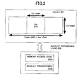
- Figure 2 illustrates one embodiment of an organization for an image in memory.
- Figures 3A-F illustrate a transform memory organization for various levels depicting conceptually how coefficients may be stored for the forward ( Figures A-C) and inverse ( Figures 3D-F) transforms.
- Figures 4A and B illustrate embodiments of a single memory where the input image data and the various decomposition levels of the image data can be stored during forward and inverse transforms, respectively.
- Figure 5 illustrates one embodiment of the process of handling the input data.
- Figure 6A illustrates a system having a progression order conversion parser.
- Figure 6B illustrates a progression converter converting from a resolution progressive codestream to a quality progressive codestream.
- Figure 7A shows multiple ways to convert a codestream from one progression order to another.
- Figure 7B shows one embodiment of simplified conversion paths to convert a codestream from one progression order to another.
- Figure 8 illustrates one embodiment of a process for performing progression order conversion.
- Figure 9 illustrates a decoder that selects portions of a codestream based on sideband information.
- Figure 10 is a flow diagram of a process for using layers when decoding.
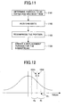
- Figure 11 is a flow diagram of one embodiment of an editing process.
- Figure 12 illustrates a bell-shaped curve of a range of values that are quantized to a particular value.
- Figure 13 is a flow diagram of one embodiment of a process to reduce flicker.
- Figure 14 illustrates one embodiment of an encoder (or portion thereof) that performs the quantization to reduce flicker.
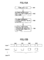
- Figure 15A illustrates a process for performing rate control.
- Figure 15B illustrates an exemplary number of layers that may be subjected to first and second passes.
- Figure 16 illustrates one embodiment of the process for accessing the groupings of tile parts.
- Figure 17 and 18 illustrate quantizers for one component for a three level 5,3 transform.
- Figure 19 illustrates an example of HVS weighted quantization.
- Figure 20 is a block diagram of one embodiment of a computer system.
- Figure 21 illustrates an example progression with tile parts for a single server.
- Figure 22 illustrates an example of layering for a 5,3 irreversible transform.
- Figure 23 illustrates an example in which transform has 5 levels and the data is divided up into layers 0-3.
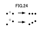
- Figure 24 illustrates one example of a situation in which flicker may be avoided in which values in first and third frames are used to set the value in the second frame.
- Figure 25 is a block diagram of a prior art decoding process that includes color management.
- Figure 26 illustrates one embodiment of a non-preferred camera encoder.
- Figure 27 illustrates one embodiment of a simpler camera encoder.
- Figure 28 is a flow diagram of one embodiment of a process for applying an inverse transform with clipping on partially transformed coefficients.
- the present invention also relates to apparatus for performing the operations herein.
- This apparatus may be specially constructed for the required purposes, or it may comprise a general purpose computer selectively activated or reconfigured by a computer program stored in the computer.
- a computer program may be stored in a computer readable storage medium, such as, but is not limited to, any type of disk including floppy disks, optical disks, CD-ROMs, and magnetic-optical disks, read-only memories (ROMs), random access memories (RAMs), EPROMs, EEPROMs, magnetic or optical cards, or any type of media suitable for storing electronic instructions, and each coupled to a computer system bus.
- a machine-readable medium includes any mechanism for storing or transmitting information in a form readable by a machine (e.g., a computer).
- a machine-readable medium includes read only memory ("ROM”); random access memory (“RAM”); magnetic disk storage media; optical storage media; flash memory devices; electrical, optical, acoustical or other form of propagated signals (e.g., carrier waves, infrared signals, digital signals, etc.); etc.
- Figure 2 shows one embodiment of an organization for an image in memory 201.
- the amount of an image in memory 201 is equal to the image width multiplied by the tile height.
- Inside the band of the image is at least one tile, such as tile 210.
- the wavelet transform processing logic 202 includes memory access logic 202A to read data from and store data to memory 201 to enable wavelet transform 202B to be applied to the data (image data or coefficients depending on the level of coefficient).
- Wavelet processing logic 202 may comprise hardware, software or a combination of both.
- access logic 202A accesses the tile with four parameters: a pointer or index to the start of the tile in memory, the width of the tile, the height of the tile, and the line offset to get from the start of one line to another (the image width).
- access logic 202A accesses memory 201 using a pointer or index to the end of the tile instead of the width of the tile.
- the following process may be used.
- One of the functions F may include applying a wavelet transform on pairs of lines.
- another function F may be a DC level shift, multiple component transform.
- processing logic may comprise hardware (e.g., dedicated logic, circuitry, etc.), software (such as is run on a general purpose computer system or a dedicated machine), or a combination of both.
- coefficients from a subband are accessed using a similar scheme with a starting point, width, height and line offset. Because rows of coefficients are stored together in memory, rows may be accessed efficiently when stored in cache, burst accessible memories or memories that are wider than one coefficient.
- Figures 3A-C show a transform memory organization for various levels depicting conceptually how coefficients may be stored. All LH, HL and HH coefficients (using the nominclature of ITU-T Rec.T.800/IS0/IEC 154441:2000 JPEG 2000 Image Coding System) are coded. These coefficients are represented by dotted lines in Figures 3B and C. Input lines of input tile 301 and LL coefficients (shown as solid lines in Figures 3B and 3C in successive levels) only need to be stored temporarily while computing the transform with the exception of the final transform level's LL coefficients which are coded. When a transform is used that does the horizontal and vertical transforms in one pass and uses line buffers, once a pair of input rows has been completely read (input lines or LL coefficients), the space used by lines can be reused.
- Figures 3A-C show input tile 301, level 1 (L1)(302) and level 2 (L2)(303) memory areas aligned with an offset to indicate how reuse might be accomplished in one embodiment.
- the addition of four rows, rows 341-342, to the memory space used to hold the L1 coefficients is needed to generate the L2 coefficients when reusing the memory storing the L1 coefficients for L2 coefficients. (Note that there are two rows between rows 341 and 342 that are wasted space.)
- the additional lines are preferably behind the direction the wavelet transform is being applied to the information in the memory.
- a pair of input rows input tile 301 corresponds to one row of each of LL, LH, HL and HH coefficients at level 1, resulting from the application of a transform to two different lines and the results of applying the wavelet transform being written into lines of the memory.
- the results of applying a wavelet transform to input rows,310 and 311 are the coefficients in portions of rows 312 and 313 of L1 coefficients (302).
- LL coefficients 321 of row 312 corresponds to the LL coefficients (solid line) of level 1
- HL coefficients 322 of row 312 corresponds to the HL coefficients of level 1
- LH portion 323 of row 313 corresponds to the LH coefficients of level 1
- HH portion 324 corresponds to the HH coefficients of level 1.
- the level 1 coefficients from the first two input lines are stored in two extra rows at the top of the memory with the remaining level 1 coefficients being written into the locations storing the data of input tile 301 to reuse the memory.
- the width and height for each type of coefficient (e.g., LH, HL, HH) for each subband of level 1 coefficients is half that of input tile 301.
- the line offset from the LL row to the next LL row for level 1 is twice the tile width (since each coefficient row is from an area corresponding to two lines).
- the results of applying the wavelet transform to two rows of LL coefficients at level 1 are the coefficients in two rows namely LL coefficients (331), LH coefficients (332), HL coefficients (333) and HH coefficients (334) at level 2.
- the width and height for level 2 coefficients is a quarter that of input tile 301.
- the line offset for level 2 is four times the tile width (since each coefficient row is from an area corresponding to two level 1 LL rows or four input lines).
- four extra lines of memory are needed to use the same memory that is storing the input tile to store the L2 coefficients. Note that if a third decomposition level was being performed, an additional 8 lines would be needed.
- a total of 14 extra lines are needed to enable reuse of the memory that stores an input time and has two levels of decomposition applied thereto.
- a general formula may be used to determine the number of extra lines is as follows: 2 (maxlevel+1) -2.
- this extra space may be reused.
- Figures 3D-3F illustrate the corresponding inverse transform memory usage in which additional lines store the results of applying an inverse transform and those additional lines are in the memory behind the direction the inverse transform is being performed.
- Figure 4A shows one embodiment of a single memory where the input and the various levels can be stored during application of a forward transform. Referring to Figure 4A, locations for the input tile, level 1 coefficients, level 2 coefficients, and level 3 coefficients is shown with the added 2, 4 and 8 lines respectively.
- Figure 4B shows a similar single memory embodiment where the input coefficients of various levels of the transform can be stored along with the output during application of an inverse transform.
- Table 1 shows the amount of memory required for various transform levels for a 256x256 tile for separate memories and reused memory.
- Level 4 For reused memory, the amount listed is the additional new memory used for that level. For this example, reusing memory for levels 1, 2 and 3 saves memory. Level 4 may use a separate memory.
- the memory for levels 4, 5 and 6 could be placed in a single memory after level 3 has been generated or in a completely different and separate memory.
- the amount of memory necessary is 38x32, which is less than 5x256. Because there are two unused lines after generating the level 1 coefficients (i.e., the memory that stored the last two lines of input data), a small memory savings can be achieved by letting the levels 4, 5 and 6 reuse these two lines. This is particularly important because the number of additional lines for levels 4, 5, and 6 is 16, 32 and 64, and the extra space between the lines will be twice as far and half as wide as the level before.
- coefficients from levels 4, 5, and 6 are packed in a smaller memory structure, such as storage area 450 in Figure 4.
- the level 4 coefficients are stored in an area having a height equal to the tile height divided by 8 (2 3 where 3 corresponds to the number of levels) and a width equal to the tile width w divided by 8 (2 3 where 3 corresponds to the number of levels previously stored elsewhere).
- An additional two lines 451 are all that is needed to store level 5 coefficients in the same necessary storage area.
- an additional four lines is all that is necessary to accommodate using this memory storage area for the level 6 coefficients. Note that no lines are skipped when storing the coefficients.
- the extra 5 lines at the bottom of storage area 430, two lines 421 and approximately 4.75 lines 422 are used to accommodate storage area 450. As shown, the approximate by three lines 422 represent allocated memory or in addition to that necessary to store the input tile. In this manner, the storage area for the input tile is almost completely reused.
- level 6 is stored separately from levels 4 and 5. However, this only saves 64 bytes of memory.
- a memory a little smaller than 273x256 can hold all the transform coefficients for a 256x256 tile. This is less than 7% more than a true in-place memory organization. Unlike an in-place memory organization, extra copies are avoided while simultaneously keeping the rows packed together for fast access.
- Table 2 shows another example of using separate versus reused memory for 128x128 tiles.
- the first three transform levels can reuse memory in a 142x128 buffer.
- a decision to use in-place memory or new memory is a function of tile height and transform level. Such a decision may be based on the following:
- tile height is inconvenient.
- a single fixed memory organization can be used.
- Tile sizes smaller than 128x128 typically result in bad compression performance, so would typically not be used.
- tile sizes bigger than 1Kx1K can be used for very large images, this does not significantly improve compression and the large amount of memory required would typically be burdensome. Therefore, assuming a tile height between 128 and 1024 inclusive and using in-place memory for 3 levels of the transform is a good heuristic.
- Decoding is similar in that the results of applying an inverse transform are written ahead of where the decoding processing logic is reading, with the only notable difference being that the start is from the highest level to the lowest level, such as level 6 to level 1 in the example above.
- the input tile ends up at the top of the memory structure.
- the extra lines to accommodate the memory reuse are in decreasing order. For example, using the structure of Figure 4B, 8 lines would be necessary to create the L2 coefficients from the L3 coefficients, 4 extra lines would be necessary to create the L1 coefficients from the L2 coefficients and 2 extra lines would be necessary to create the input tile from the L1 coefficients.
- a color conversion may be performed on the data prior to encoding.
- Figure 5 illustrates one embodiment of the process of handling the input data.
- color input pixels are received in raster order. These color pixels may be in RGB, YCrCb, CMY, CMYK, grayscale, etc.
- the color input pixels may be stored as tiles in a memory, such as memory 501, by band (or other forms).
- Pixels from storage 501 or received directly form the input undergo color conversion and/or level shifting, with the resulting outputs being stored in one coefficient buffers 502 1 -502 N . That is, once the color conversion has been completed on each tile, it is stored in one of the coefficient buffers 502 1 -502 N , and then the next tile can be processed. In one embodiment, there is one coefficient buffer for each component.
- Coefficient buffers 502 1 -502 N are used by the transform in the manner described above to perform the wavelet transform while reusing memory. Thus, coefficient buffers 502 1 -502 N are both input and output to wavelet transform.
- the context model 503 and entropy coder 505 can perform further compression processing on the already transformed data.
- the coded data is buffered in coded data memory 505.
- the transform may be applied to another tile. Similarly, any or all the operations may be performed on multiple tiles at the same time.
- data in a compressed codestream can be stored in one of the five progression orders.
- the progression order can change at different points in the codestream.
- the order is defined by embedded "for layers" on layers, precincts, resolution, and components.
- progression orders are described in the standard in Table A-16 of the JPEG 2000 standard. They arelayer-resolution-component-position progression (LRCP), resolution-layer-component-position progression (RLCP), resolution-position-component-layer progression (RPCL), position-component-resolution-layer progression (PCRL), component-position-resolution-layer progression (CPRL).
- LRCP layer-resolution-component-position progression
- RLCP resolution-layer-component-position progression
- RPCL resolution-position-component-layer progression
- PCL position-component-resolution-layer progression
- CPRL component-position-resolution-layer progression
- the order may be defined in the COD or POC markers of the JPEG 2000 standard.
- the Coding style default (COD) marker is defined by the JPEG 2000 standard and describes the coding style, number of decomposition levels, and layering that is the default used for compressing all components of an image (if in the main header) or a tile (if in a tile-part header).
- the Progression order change (POC) marker describes the bounds and progression order for any progression order other than that specified in the COD marker segments in the codestream.
- the Packet Length Main Header indicates a list of packet lengths in tile-parts for every tile part in order and the Packet Length, Tile-part header (PLT) indicates tile packet lengths in a tile-part and indicates where the data is in the codestream.
- the JPEG 2000 standard in section B.12 only specifies how packets of compress data are formed for a given progression order. It does not describe how data should be converted from one progression order to another progression order.
- a progression order converting parser converts a codestream to a desired progression order based on the user input without decoding the data and then encoding it again.
- Figure 6A illustrates a system having such a parser.
- parser 601 receives requests from a client for a particular progression order. The client may be viewing a web page and selects a particular link.
- parser 601 accesses server 602 to obtain the codestream associated with full image 603 from memory 604 and converts the codestream into a different progression order based on the request.
- the request indicates the progression order by using an optional command (e.g., RL2L (Resolution-layer progression to Layer Progression)).
- the progression order that is described may be based on layer, resolution, component, precinct, or tile.
- Figure 6B illustrates the progression converter converting from a layer progressive codestream (LRCP) to a resolution progressive (RLCP) codestream.
- LRCP layer progressive codestream
- RLCP resolution progressive
- Figure 7A shows multiple ways to convert a codestream from one progression order to another.
- each of the five progressions (LRCP, RLCP, RPCL, CPRL, and PCRL) are shown with paths to each of the others, such that all progressions are shown.
- the parser causes all conversions to go through the layer progression first and then to a selected conversion.
- Figure 7B shows one embodiment of such simplified conversion paths in which the number of required mappings is reduced from 10 (as in Figure 7A) to 4.
- any one of the five progression orders could be used as the one to which all are converted before arriving at the selected order.
- the conversion technique described herein simplifies source codes in that the number of lines of source code is much less than the multiple ways of conversion. This results in less debug time and fewer memory and run-time variables.
- the order of the packets in the codestream must be reordered.
- the packets are labeled by their sequential order in the codestream.
- Markers may indicate the starting point of the data, the length of the data (or alternatively the endpoint of the data) and how the data should be handled.
- the indication of how the data is to be handled may indicate whether the data is to be deleted, whether the data is to be truncated, or some other operation to be performed on the data.
- Such handling information may also come from rate distortion information, such as may be provided in a PLT/PLM and/or the PPT/PPM marker sets of the JPEG 2000 standard. In this manner, the codestream may be truncated without changing the packet header.
- a list, array, or other structure (such as reordering structure 601A) is built by indicating the portion of data in each packet. Using this structure, the packets may be reordered.
- Figure 8 illustrates one embodiment of a process for performing progression order conversion.
- the process is performed by processing logic that may comprise hardware (e.g., dedicated logic, circuitry, etc.), software (such as is run by, for example, a general purpose computer or dedicated machine), or a combination of both.
- processing logic may comprise hardware (e.g., dedicated logic, circuitry, etc.), software (such as is run by, for example, a general purpose computer or dedicated machine), or a combination of both.
- processing logic begins by processing logic building a list from headers in the packets (processing block 801) and optionally marking list items "delete" for quantization (processing block 802).
- processing logic reorders the list to map the original progression to a desired progression (including handling input and output with progressions specified with POC markers (bounds on the progression order) (processing block 803).
- processing logic outputs coded data based on reordered list (processing block 804).
- the following is an example showing how packets are arranged in a codestream.
- the codestream was formed based on 2 components, 2 layers, 3 decomposition levels, and layer progression.
- Table 4 shows the packet order, length and association index of packets in the example.
- the packet order column shows the sequential order of packets placed in a codestream.
- the length indicates the length of the packets.
- the association index shows the resolution, layer, component, and precinct of the packet.
- packet[0] is the first packet in the codestream after the first tile header. It has a length of 589 bytes.
- Association index RwLxCyPz indicates the packet belongs to resolution w, layer x, component y and precinct z.
- packets are grouped based on the layer in which they reside.
- the first 8 packets belong to Layer 0.
- the following 8 packets belong to Layer 1.
- the above codestream is converted to resolution layer progression.
- the following shows how the above packets are re-ordered.
- Bit hiding allows sideband information to be transmitted without increasing the file size. Sideband information that does increase file size but does not break naive decoders might also be valuable (although the COM marker defined by the JPEG 2000 standard might be used instead).
- Some marker segments, packet headers and packets are padded out to the nearest byte.
- Examples of the JPEG 2000 marker segments include PPM, PPT, PLM, and PLT.
- some marker segments can be longer than they need to be including QCD, QCC, and POC. In all of these cases, the padded data values are not defined.
- a hint might include an index to a particular enhancement scheme. For example, if it is known that an image is mostly text, a value may be sent that indicates that a first post-processing filter is to be used. On the other hand, if the area is mostly a graphic image, then a value may be sent that indicates that a second post-processing filter is to be used.
- bits may be hidden or sideband information may be stored in the codestream.
- each packet header With respect to each packet header, the end of a packet header is rounded to a byte boundary. Therefore, there may be 1 to 7 bits that may be available for sending extra information at times when rounding would have been necessary. Similarly, each packet is rounded to a byte boundary, thereby providing 1 to 7 bits (assuming that rounding would have been necessary). Also the last packet in a tile-part can be extended a few bytes. These extra bytes may be used to send additional information.
- the length of the compressed data for a code-block can be given in the packet header with a non-minimum representation.
- the choice of representation e.g., a non-minimum representation
- tag trees are like a quadtree of minimum values.
- An example tag tree, which is minimal for the 4x4 arrangement above is as follows: 3 0 2 7 4 7 10 5 2 0 17 16 0 73 37 0 4 10 0 7 19 in which "3" is added to every codeblock's value, and "0", "2", "5" and “2" are each added to the 4 corresponding codeblocks.
- the minimal tag tree is created by taking the first 2x2 group in the 4x4 arrangement above and look at minimum value is out of the four values.
- the minimum value is 3. This is then performed on the other 2x2 blocks. Then these identified minimum values are evaluated again to determine their minimum, which would be "3" in the example. Then the minimum value is subtracted from the four minimum values to create the following 0 2 5 2 Then, for the remaining numbers in the 4x4, the number 3 is subtracted from each value along with the value in the 2x2 that corresponds to the particular value in the 4x4 arrangement, thereby resulting in the tag tree above.
- variable length code may be used that efficiently represents small numbers.
- the 1 bit block represents the 1 in the 2x2 block above indicates it is not part of a minimal tag tree, but can be used to convey some particular information to a decoder. Likewise if a 2 was the minimal value in the 2x2 block, such a fact may convey different information to a decoder.
- the JPEG 2000 POC, QCD, and QCC markers can have redundant entries. It is as if the codestream were quantized and the markers were not rewritten. For example, the QCD and QCC markers have values for a number of subbands specified by the syntax of the marker. If there are fewer subbands actually coded in the bitstream, data may be hidden in the values used for the missing subbands. The redundant entries may be replaced and used for hidden or sideband information.
- the hidden or sideband information may include post-processing hints (such as, for example, sharpen this tile with a specified filter or strength, or smooth, or perform optical character recognition (OCR) on this region, etc.), decoding hints, security (such as, for example, an encryption key for decoding the remainder of the image or another image, etc.) codestream identification (such as, for example, labeling POTUS as the originator of the file, etc.) and/or other information.
- post-processing hints such as, for example, sharpen this tile with a specified filter or strength, or smooth, or perform optical character recognition (OCR) on this region, etc.
- decoding hints such as, for example, an encryption key for decoding the remainder of the image or another image, etc.
- security such as, for example, an encryption key for decoding the remainder of the image or another image, etc.
- codestream identification such as, for example, labeling POTUS as the originator of the file, etc.
- Layers are part of the JPEG standard.
- sideband information possibly in a COM marker, is used by the decoder to allow selecting of layers during decoding.
- the sideband information may be used to select layers for postcompression quantization to meet rate/distortion targets for different viewing distances, different resolutions, different regions of interest, different frequency content for analysis (e.g., finding edges of text).
- the layers are predefined based on rate. For example, the first layer represents a 1-bit per pixel image, while the second layer represents a 2-bit per pixel image, etc. Therefore, the layers run from the lowest quality to the highest quality. Likewise, target rates can be met for lower resolutions as well.
- the sideband information may be stored in a marker segment of the codestream.
- the JPEG 2000 comment (COM) marker is used to provide information about the layers.
- the COM marker may be used to indicate the number of bytes for each resolution and/or rate across the entire image or a relative number of bytes for each additional layer.
- Table 6 indicates each layer and its resolution in the number of bytes across the tile in an image. Such a table may have distortion values instead.
- the ordering could be by layer.
- the information above is consolidated for each level (not segregated by level or component), as shown below:
- Distortion by layers can be based on PSNR.
- PSNR Physical Broadband Noise Ratio
- such information may be hidden in the codestream as described above.
- the information may be used to control rate distortion.
- the layers may be predefined for a particular viewing distance.
- the data is divided into layers from the highest frequency, lowest resolution to the lowest frequency, highest resolution.
- the layer information indicates the summation of bits across the entire image for that layer and all previous layers (for example the 16,011 bits listed next to layer 1 indicates the total number of bits for layer 0 and layer 1).
- bytes, words, kilobytes, or other units of memory or rate could be used instead of bits.
- Table 7 shows this type of absolute rate information.
- Table 8 shows relative rate information.
- Layer 0 has 4096 bits, layer 1 has 11,915 bits, etc.
- layer Rate (bytes) 0 4,096 1 16,011 2 40,000 3 100,000 4 250,000 5 500,000 6 1,000,000 7 2,500,000 8 5,500,000 layer Rate (bytes) 0 4,096 1 11,915 2 23,989 3 60,000 4 150,000 5 250,000 6 500,000 7 1,500,000 8 3,000,000
- the decoded image For example, if only 750,000 bytes may be allowed in the decoded image, then all that can be decoded (as the 1,000,000 bytes tabulated with layer 6 includes the 500,000 bytes of layers 0-5) is through layer 5 and half of importance layer 6. In some embodiments, no packets from layer 6 would be included. In other embodiments, some packets from layer 6 would be included and others would be replaced by zero packets so that the total amount of layer 6 data was approximately 250,000 bytes.
- Figure 22 illustrates an example of layering for a 5,3 irreversible transform with three levels, MSE or similar. Referring to Figure 22, there are 45 layers shown. Each additional layer improves MSE in an order that gives good rate-distortion for MSE.
- Figure 23 illustrates another example in which transform has 5 levels and the data is divided up into layers 0-3.
- Layer 0 corresponds to the thumbnail version
- layers 0-1 correspond to the monitor (or screen) resolution
- layers 0-2 correspond to the print resolution
- layers 0-3 correspond to lossless.
- the layers may be predefined for some other distortion metric (e.g., MSE, weighted MSE, sharpness of text, etc.)
- decoder 901 receives a codestream and includes quantization logic 902 that examines the COM marker and uses information about the viewing distance it is at stored in storage 903 to generate quantized codestream 904 via, for example, selecting the proper layers.
- Quantized codestream 904 is decoded by decoding logic 905 (e.g., a JPEG 2000 decoder) after selecting layers to generate an image data 906. A naive decoder would simply ignore the data in the comment marker.
- Figure 10 is a flow diagram of a process for using layers when decoding.
- the process is performed by processing logic that may comprise hardware (e.g., dedicated logic, circuitry, etc.), software (such as is run by, for example, a general purpose computer or a dedicated machine), or a combination of both.
- processing logic may comprise hardware (e.g., dedicated logic, circuitry, etc.), software (such as is run by, for example, a general purpose computer or a dedicated machine), or a combination of both.
- the process begins by processing logic receiving a codestream of compressed logic data (processing block 1001).
- the image data is organized into multiple layers, each of which comprises coded data that adds visual value to the image (e.g., look sharper, better defined, better contrast, etc.).
- Next processing logic selects one or more layers for quantization based on sideband information (processing block 1002). After selection, processing logic decompresses the non-quantized layers of the codestream (processing block 1003).
- a codestream it may be desirable to edit parts of the image. That is, for example, after performing encoding to create the codestream, a set of tiles may be decoded. After decoding the set of times, editing may be performed, followed by encoding the set of tiles with the edits to the same size as the encoded tiles were prior to their decoding. Examples of typical editing include sharpening of text and removing "red-eye.”
- the JPEG 2000 codestream can be edited in memory or in a disk file system without rewriting the entire codestream.
- Figure 11 is a flow diagram of one embodiment of an editing process.
- the process is performed by process logic that may comprise hardware (e.g., dedicated logic, circuitry, etc.), software (such as is run by, for example, a general purpose computer or a dedicated machine), or a combination of both.
- process logic may comprise hardware (e.g., dedicated logic, circuitry, etc.), software (such as is run by, for example, a general purpose computer or a dedicated machine), or a combination of both.
- processing logic initially determines the tiles, tile-parts, or packets that cover the area, resolution, components, and/or precincts to be edited and decodes them (processing block 1101). This determination may be made in response to a user selecting an area and/or working resolution. The determination may use editing information for a higher resolution to determine which parts or tiles cover the portion to be edited. Once decoding has been completed, processing logic performs the desired edits (processing block 1102).
- processing logic After performing the desired edits, processing logic recompresses the data into coded data (processing block 1103) and creates a replacement tile, tile-part, or packet for the codestream (processing block 1104).
- processing logic pads out the data with bytes at the end of the codestream if the new data is smaller than the unedited version of the data to make the replacement tile, tile-part or packet the same size as the unedited version.
- processing logic may use a marker, or tag, such as a COM marker segment of the appropriate length instead of the padding.
- a marker or tag, such as a COM marker segment of the appropriate length instead of the padding.
- the COM marker could be used to fill space or could contain information that the encoder wanted to include. It could contain information such as, for example, sideband information described herein or a copyright license for an image or text or other file format information.
- processing logic in creating the replacement tile, tile-part, or packet, truncates the last packets for any or all components until the data fits in the codestream if the new data is larger than the unedited version of the data.
- Editing of an image may be performed by changing coded data for tiles, tile-parts, or codeblocks. In one embodiment, editing is performed without changing file size by quantizing instead of expanding. In another embodiment, a predetermined amount of extra space is allocated per tile or per codeblock to allow for a predetermined amount of expansion. In still another embodiment, coded data may be put at end of files by manipulating tile headers and putting invalid tile data in COM markers.
- tile-parts that depend on the data in the portion of the codestream that is being edited, these tile-parts may become useless in the codestream.
- An indication of this useless data may be noted to the decoder by one of several methods. These methods involve inserting or modifying information in the codestream to indicate the presence and/or location of the useless data.
- the application uses a status buffer to indicate that the data in tile-parts subsequent to an edited tile-part may be useless.
- the status buffer may be in workspace memory and describes dependencies between packets. If an earlier packet is altered, the subsequent packets cannot be decoded as is. These subsequent packets must be edited accordingly or eliminated.
- such an indication may be made by zeroing out the data section of those tile-parts and/or creating a PPT marker segment that denotes no data.
- unquantized coefficients from some or all subbands may be divided by a value of Q to create the quantized coefficient values.
- This value Q may have a wide range of values.
- Typical encoders quantize a number of the values in a single particular range of values is made equal to one single coefficient value. In essence, all the coefficients in the particular range are quantized to the same value.
- Figure 12 shows that the range of values is often in a bell shaped curve and that all of the values in the particular range, such as range R 1 are sent to the decoder as one quantized value, such as R ' / 1, and the decoder will reconstruct these values to a particular value.
- a decoder reconstructs these values to a predetermined value (e.g., floor (1 ⁇ 2 min + 1 ⁇ 2 max), or min + 1 ⁇ 2 Q, where Q is the quantization step size). For example, if the range of values is between 16 and 31, then the decoder may assume the value is 24. In one embodiment, instead of using 1/2 as the value, another value is selected, such as floor (3/8 min + 5/8 max), or min + 3/8Q, where Q is the quantization step size. Therefore, if the range is from 16 to 31, then it is assumed that the decoder will reconstruct the value to 22, instead of 24.
- a predetermined value e.g., floor (1 ⁇ 2 min + 1 ⁇ 2 max), or min + 1 ⁇ 2 Q, where Q is the quantization step size.
- two spatially adjacent coefficients may be close to each other numerically yet in separate quantization bins, such as coefficient values 1201 of range R 2 and 1202 of range R 1 in Figure 12.
- the results of the quantization may cause an artifact to occur.
- the encoder selects a bin such as Range R 1 into which a coefficient, such as coefficient 1201, will be quantized so that it is consistent with neighbors, such as coefficient 1202. This helps avoid artifacts. That is, this technique reduces distortion yet may increase rate, particularly when a coefficient is moved from a smaller bin to a higher bin.
- flicker occurs when applying wavelet compression to motion sequences.
- An example of such flicker may include the image getting brighter or darker in areas or the appearance of edges changing in successive frames as the motion sequence is played (mosquito noise around the edges).
- the flicker may be due to the application of different local quantization to successive frames of a motion sequence or to noise exacerbated by quantization that is viewed temporarily.
- FIG. 13 is a flow diagram of one embodiment of a process to reduce flicker.
- a test of whether to apply such quantization to a coefficient value in a subsequent frame is based on the quantization that was performed on the coefficient in the previous frame.
- the encoder is utilizing frame dependency to eliminate flicker while the decoder decodes data frame by frame independently.
- coefficient values are modified (quantized) based on their relationship with each other with respect to a threshold. For example, if Dn and Dn+1 are the corresponding coefficient (same spatial location and same subband) in two frames before quantization, if D'n and D'n+1 represent these coefficients after quantization, if Q(•) are scalar quantization, and if the value T is a threshold, then the following may be applied: if (
- the value T may be twice the quantization step size. Other values of T include, but are not limited to, 2 Q , 1.5 Q , 2 2 Q .
- One of the coefficient values may be modified to be either a predetermined closeness to another coefficient value.
- the closeness may be determined by some threshold.
- the threshold may be user set or adaptive based on some criteria. The threshold could be different based on the subband and, perhaps, on the persistance of the particular value (number of frames that this coefficient is close).
- the coefficient value is set equal to the other coefficient value. In alternative embodiments, the coefficient is set to be within the quantization bin size of the other coefficient value or twice the quantization bin size.
- Figure 14 illustrates one embodiment of an encoder (or portion thereof) that performs the quantization described above.
- a quantizer 1400 receives coefficients 1410 for frames of a motion sequence from a wavelet transform (not shown). The coefficients are received by quantization logic 1401 which compares a threshold value stored in memory 1401 to coefficient values for the previous frame that are stored in memory 1403 to coefficients 1410 with a scalar quantizer Q applied from memory 1404.
- Quantization logic 1401 may comprise comparison hardware (e.g., logic with gates, circuitry, etc.) or software to perform the comparison. This comparison hardware and software may implement a subtractor or subtraction operation. The results are a quantized codesteam (assuming some values have been changed.)
- Figure 24 illustrates one example in which values in a first and third frame are used to set the value in the second frame.
- quantization can also be codestream quantization with a code block-based rule.
- selective quantization of coefficients can be performed during encoding by setting a subset of the refinement bits to be the more probable symbol (MPS). This may be performed at a user selected bitplane. For examples, if there is text on a background image, with a goal of having sharp text images while minimizing coded data required for the background, the refinement bits that are set to MPS are those that do not effect text for the last bitplane, while using the actual value for bits that effect text.
- MPS more probable symbol
- Such a quantization scheme may be used to implement non-uniform quantization step sizes. For example, if one wanted to have a background with fewer bits, setting the refinement bits to the MPS could operate as a form of quantization. This quantization scheme causes some level of distortion but lowers the bit rate necessary to transfer the codestream.
- the same technique may be applied to other changes between frames. That is, in one embodiment, a change due to a rate distortion in one frame may be performed in a subsequent frame to avoid distortion effects.
- user specified quantization is provided.
- 7 quantization values are sufficient: level 1 HH, level 1 HL and LH, level 2 HH, level 2 HL and LH, level 3 HH, level 3 HL and LH, and level 3 LH.
- quantization values are bitplanes to truncate (which is equivalent to scalar quantization by powers of 2), 3-bit values (0...7) are sufficient for most applications. (For image components with depth 12-bits or more and 5 or more transform levels, perhaps higher quantizations might be useful.) Values 0...6 could be used to specify the number of bitplanes to truncate and 7 could be used to mean discard all bitplanes.
- the three bit values may be written to a controller that controls compression (or decompression) hardware (e.g., JPEG2000 compatible hardware) to perform the quantization.
- Quantizers can also be used to assign bitplanes to layers.
- Q 0 , Q 1 , and Q 2 may be quantizers that specify bitplanes of coding pass to quantize.
- Quantizer Q 0 causes the most loss, while quantizer Q 2 causes the least loss.
- Layer 1 is all the data quantized by Q 0 but not quantized by Q 1 .
- Layer 2 is all the data quantized by Q 1 but not quantized by Q 2 .
- Layer 3 is all the data quantized by Q 2 .
- Figures 17 and 18 show example quantizers (label A...Q) for the 3-level 5/3 transform as the number of coefficient LSBs to truncate or not code. Truncating N bitplanes is equivalent to a scalar quantizer of 2 N . The subband where the quantization changes with respect to the previous quantizer is highlighted with a dashed box. The quantizers D, K and Q all have the same relationship between the subbands. Other quantizers might be used that are better for MSE or for other distortion metrics.
- the exemplary Verilog below converts a single quantization value "q" into seven quantizers (number of LSBs to truncate).
- the variable q_1_HH is used for level 1 HH coefficients
- the variable q_1_H is used for level 1 HL and LH coefficients, etc.
- Some consecutive values of q result in the same quantizer: 0 and 1; 2 and 3; 4 and 5; 8i+6 and 8i+7 for all integers i with i ⁇ 0.
- Table 9 shows additional bitplanes to quantize (e.g., truncate) for luminance to take advantage of the frequency response of the Human Visual System (from Table J-2 of the JPEG 2000 standard).
- a viewing distance of 1000 pixels might be appropriate for viewing images on a computer monitor. Larger viewing distances might be appropriate for print images or television.
- Figure 19 shows a quantization that starts with Figure 17(D) and then adds frequency weighting for a 1000 pixel viewing distance (to both luminance and chrominance), keeps 3LL chrominance unchanged, discards 1HL and 1HH chrominance for 4:2:2 and additional 2 bitplanes are discarded for the remaining chrominance.
- the LL (DC) coefficients are quantized more heavily for text than for non-text images at low bitrate. For example, for an 8-bit image component, a quantiation step size of 8, 16 or 32 might be used for text only regions and a quantization step size of 1, 2 or 4 might be used for regions containing non-text. This allows more fidelity for the high frequency coefficients, thereby resulting in text with sharp edges.
- Table 10 shows 16 example quantizers. Quantizer 15 is lossless. Quantizer 8 is the same as Figure 19. These can be used divide the subband bitplanes into layers. subband 0 1 2 3 4 5 6 7. 8 9 10 11 12 13 14 15 Y 1HH all all 6 6 5 5 4 4 3 3 2 2 1 1 0 0 Y 1HL,LH 6 5 5 4 4 3 3 2 2 1 1 0 0 0 0 0 Y 2HH 5 4 3 3 2 2 1 1 0 0 0 0 0 0 0 Y 2HL,LH 4 4 3 3 2 2 1 1 0 0 0 0 0 0 0 0 0 Y 3HH 4 3 3 3 2 2 1 1 0 0 0 0 0 0 0 0 0 Y 3HH 4 3 3 3 2 2 1 1 0 0 0 0 0 0 0 0 0 0 Y 3HH 4 3 3 3 2 2 1 1 0 0 0 0 0 0
- Layer 0 contains all data not quantized away by quantizer 0. This would be luminance data only: all of 3LL; all but 4 bitplanes of 2HL, 2LH, 3HL, 3LH and 3HH; all but 5 bitplanes of 2HH and all but 6 bitplanes of 1HL and 1LH.
- Layer 1 contains all data not in layer 0 and not quantized away by quantizer 1. This would be luminance bitplanes 5 for 1HL and 1LH, bitplane 4 for 2 HH, bitplane 3 for 3HL and 3LH; all 3LL chrominance; all but 5 bitplanes for chrominance 3HL and 31H; and all but 6 bitplanes for chrominance 2HL, 2LH and 3HH.
- layer 15 would contain the LSB of 1LH chrominance.
- the simplist method is to pick a distortion for every "unit" compressed (a unit may be an 8x8 block in JPEG, a frame in a motion sequence, a tile of a single image, a subband of a tile in a wavelet coded image, etc.). If the distortion selected leads to a bitrate higher than the desired average bitrate, the distortion allowed is increased for new units as they are compressed. If the distortion selected leads to a bit rate lower than the desired average bitrate, the distortion allowed is decreased for new units as they are compressed.
- a more complex method buffers the compressed data from some number of "units.”
- the bitrate and/or distortion for each unit at each distortion level is stored. Then the distortion to allow across all the units in the buffer is determined when the buffer is full. If the buffer is sufficient to contain the entire image, extremely high quality results can be obtained.
- layers are designed to contain increments to quality. Thus, selecting a distortion can mean selecting the number of layers to use for each code block or tile.
- a complete description of this type of rate control is in, David Taubman, "High Performance Scalable Image Compression with EBCOT," IEEE Transactions on Image Processing.
- One disadvantage is that a buffer memory for the entire codestream is required.
- a second disadvantage is that the latency (time until any of the codestream is output) is high.
- a third disadvantage is that the second pass could take large amount of time.
- each tile of a JPEG 2000 codestream is encoded as described above with at least two layers.
- a number of packets e.g., layer, resolution, precinct, tile-component
- the remaining layers are stored in the buffer.
- a second pass through the remaining coded data in the buffer is optional.
- extra packets from each tile are appended to the codestream as complete tile-parts as space or time allows. If in a fixed-rate application, then only packets within the given rate are appended. If in a fixed time application, then only number of cycles allowed.
- Figure 15A One embodiment of this process is shown in Figure 15A. Thus, these can be the 2 complete tile-parts output for each tile.
- Figure 15B illustrates a number of layers, layers 1-n.
- Layer 1 is output on the first pass, and the remaining layers are most likely below fixed-time or fixed-rate time limits.
- Layer 2 may be output on a second pass within fixed-time or fixed-rate requirements while achieving similar distortion over all the components.
- the above process is advantageous in that it allows the buffer to store a fraction of the coded data, the first data can be output (transmitted or stored) sooner, and the second pass through the data can be faster because there is less data to process. Also less memory is required for buffering.
- the criterion for selecting which packets go into the first set of tile-parts can be similar to any other rate control algorithm.
- the rate of packets can be less than the desired average bitrate for the whole image. For example, if a final compressed bitstream at 2.0 bpp is desired, the first pass could place 1.5 bpp for every tile in the codestream, and buffer 1 bpp for every tile.
- the second pass can select from the remaining data the packets to place in the second tile part of each tile.
- some tiles that had high distortion after the first pass could receive all the remaining data saved for the tile, while other tile parts which had low distortion after the first pass might not have any additional data transmitted.
- Some rate control techniques described herein include rate control performed on a compressed codestream based on a request implemented by selecting some number of layers to keep in the codestream.
- a parser may be used to produce a new codestream which shows the bitrate based on layers. This bitrate is equal to or less than the bitrate specified by the request.
- the parser may use a data structure referred to herein as a "packet structure.”
- this data structure may be used for other purposes such as, for example, the versatile pocket data structure described below.
- the packet structure includes a packet start pointer and packet length. It also contains a tile number, a resolution, a component, layer, and a precinct the packet belongs to. Finally, it also consists of a selection flag. This flag, when set to a predetermined value (e.g., 1), indicates if the packet is selected in the array for writing out to a new codestream.
- packets are read in sequential order from a codestream based on the progression order information indicated by the COD marker.
- the number of bytes is computed based on the bitrate desired by the request. The number of bytes belonging to layer 0 is added up to a total. Then this total of bytes is compared with the number of bytes desired. If the total is less than the number of bytes desired, one additional layer is added to the total. The process continues until the total is equal to or greater than the number of bytes desired or all packets have been added.
- those packets which have been added to the total are marked as selected by the selection flag in the structure.
- the addition process is stopped. If the total exceeds the number of bytes desired, the packets in the last layer added are subtracted from the total. This is done to guarantee that the bitrate is below the bitrate desired. Consequently, during the subtraction step, packets which have been subtracted from the total are marked unselected.
- the related markers such as SOT, COD, PLT are updated according to the request. Packets are written to the new codestream.
- the packet structure may be created using the following:
- the same packet data structure described above can be used to facilitate other parsing options, once packets are read into the structure.
- the packets which are to be excluded are marked unselected. For example, given a 4 resolution codestream, and a request is to produce a 3-resolution codestream, a parser marks all packets which belong to resolution 4 unselected. Then the newly produced codestream contains only packets from resolution 1 up to resolution 3.
- quality parsing can be performed step by step processing the packets in the structure.
- the packet data structure can handle complex requests. For example, a request which requires the parser to produce a codestream which has a 3-resolution, 2-layer, and 1-component codestream.
- the final decoded pixels are often outside of the original range of allowed pixels from the specified bit depth. Typically, these pixels are clipped to the original range so that further image processing or display devices can use the original bit depth.
- an eight bit image has pixel values between 0 and 255, inclusive.
- the decoded image may contain values like -5 and 256. To provide an eight bit output, these values are clipped to 0 and 255 respectively. This clipping procedure always reduces pixel wise distortion because the original image did not contain pixels outside of the clipping bounds. This procedure is well known and recommend by the JPEG 2000 standard.
- the maximum value of the low pass coefficient is +191, and the minimum possible value is - 191.
- the high pass coefficient must be between -255 and 255 inclusive.
- the Low-Low coefficients are bounded by -286 and 287.
- the coefficients can be clipped to -286 and +287, and distortion will decrease.
- the low pass coefficients can be clipped to - 191, +191, and the high pass coefficients can be clipped to -255, 255.
- each filter For each subband, each filter, each transform level, and each image depth, there is a different maximum and minimum value for the coefficients. These maximum and minimum values can be computed by finding the signal that leads to the maximum and minimum and running the forward compression system and recording the maxima. The signals that lead to extreme values come from inputs where each pixel is either a maximum or minimum. Which pixels should be maximum and which pixels should be minimum can be determined by convolving sequences which are -1 when the wavelet coefficient is negative and +1 when the wavelet coefficient is negative. For the 5-3 filter used in JPEG 2000 Part I, the low pass signal of interest is [-1+1+1+1-1] and the high pass signal is [-1+1-1].
- the signal (image) which will generate the largest LL value is: +1 -1 -1 -1 +1 -1 +1 +1 +1 +1 -1 -1 +1 +1 +1 -1 +1 +1 -1 +1 -1 -1 -1 +1 (where +1 must be replaced by the input maximum (e.g., 255) and -1 must be replaced by the input minimum (e.g., 0).
- Figure 28 is a flow diagram of one embodiment of a process for applying an inverse transform with clipping on partially transformed coefficients.
- the process is performed by processing logic, which may comprise hardware (e.g., circuitry, dedicated logic, etc.), software (such as that which runs on a general purpose computer system or a dedicated machine), or a combination of both.
- processing logic may comprise hardware (e.g., circuitry, dedicated logic, etc.), software (such as that which runs on a general purpose computer system or a dedicated machine), or a combination of both.
- processing logic applies a first level inverse transform to coefficients (processing block 2801). Thereafter, processing logic clips the partially transformed coefficients to a predetermined range (processing block 2802). Next, processing logic applies a first level inverse transform to the clipped coefficients (processing block 2803) and clips the partially transformed coefficients to a predetermined range (processing block 2804), which is different than the range in processing block 2802. Again, processing logic applies a first level inverse transform to clipped coefficients (processing block 2805) and clips the partially transformed coefficients to still another predetermined range (processing block 2806).
- FIG. 25 A typical decoding process including color management is shown in Figure 25.
- a file with a file format e.g., a file format described in the JPEG 2000 standard
- Decompression block 2501 decompresses the file by taking the codestream portion of the file and performing context modeling, entropy decoding, and applying an inverse wavelet transform, but does not perform color space operations. If the codestream indicates the RCT or ICT component transform should be used to decode the codestream, these will be performed by block 2502.
- inverse RCT/ICT block 2502 takes the components and the "RCT Y/N" indication (RCT if yes, ICT is no) and performs the specified inverse transform and provides (non-display) RGB pixels. (If specified by the syntax, inverse level shifting is also performed.)
- Inverse ICC block 2503 receives the (non-display) RGB pixels and the ICC profile and applies an inverse color space transform to provide display RGB pixels.
- Figure 26 illustrates one embodiment of a non-preferred camera encoder.
- a camera generates YCrCb pixels.
- a converter 2602 converts the YCrCb pixels to RGB pixels and provides those two a typical JPEG 2000 encoder.
- the encoder comprises a RCT to ICT converter 2603 followed by a compressor 2604.
- the compressor generates an ICC A for codestream.
- Figure 27 illustrates one embodiment of a simpler camera encoder. That is, instead of including RCT/ICT converter 2603 and compressor 2604, a simple camera encoder includes only compressor block 2702.
- a camera 2701 generates YCrCb pixels and provides them to compressor 2702.
- Compressor comprises a JPEG 2000 encoder without an RCT conversion and generates an ICC B codestream with RCT equaling 1 (with syntax signaling that the inverse RCT should be used on decoding).
- ICC profiles are "syntaxes" for functions on pixels.
- a camera will typically write the same profile for all images, so ICC B is computed offline, and copied into each output file.
- ICC B is computed offline, and copied into each output file.
- the JPEG 2000 standard is typically used to handling data in a 4:4:4 format. It is not capable of describing how to reconstruct data in 4:1:1 or 4:2:2 formats in a 4:4:4 format for output.
- the encoder treats 1 HL, 1 LH and 1 HH coefficients as zero.
- the encoder treats 1 HL and 1 HH coefficients as zero.
- a decoder is able to receive the codestream in a way it expects. In other words, the encoded data resembles 4:4:4 data that has been heavily quantized.
- thumbnail images may be used as an index into a large number of images.
- a screen resolution image may be the image used to send to a monitor for display thereon.
- a print resolution image may be of lower quality for printer applications.
- a codestream of an image is organized into sections so that different versions of the image, such as, for example, a thumbnail version, a screen version, a print version and a lossless version, is progressive by quality.
- the packets are arranged such that certain packets correspond to particular resolutions such as a thumbnail.
- the combination of these packets with other packets represents the monitor resolution image, which when combined with other packets may represent the printer version, etc.
- portions of a codestream may be grouped together. For example, all the tiles of the thumbnail size may be grouped together followed by tiles for another resolution followed by tiles of another resolution, etc.
- Figure 21 illustrates an example progression with tile parts for a single server. Each tile's thumbnail is grouped in tile-parts at the beginning of a file.
- Figure 21A illustrates that tile-part 2101 is the only portion that is used for a thumbnail image.
- Figure 21B illustrates that for a monitor resolution, tile-parts 2102-2104 have been included with tile-part 2101.
- Figure 21C illustrates that for a printer resolution, tile-parts 2105 and 2106 have been included with tile-parts 2101-2104.
- Figure 21D illustrates that for a lossless version of the data, the remaining three tile-parts 2107-2108 are included with the rest of the tile-parts. These sets of tile parts may be placed on a server in this progressive order.
- FIG. 16 One embodiment of the process for accessing the groupings of tile parts is shown in Figure 16.
- the process may be performed by processing logic that may comprise hardware (e.g., dedicated logic, circuitry, etc.), software (such as is run on a general purpose computer system or a dedicated machine), or a combination of both.
- processing logic may comprise hardware (e.g., dedicated logic, circuitry, etc.), software (such as is run on a general purpose computer system or a dedicated machine), or a combination of both.
- the following steps assume that the image has been transformed with sufficient resolution levels and layers to divide the image into the four sizes.
- processing logic initially determines the correct resolution and layering for the thumbnail (processing block 1601).
- processing logic creates a POC constrained to that resolution and layer for each tile and then creates a set of tile-parts and places this POC for each tile in the codestream.
- processing logic repeats processing block 1601 for the monitor resolution given that the thumbnail packets are already in the codestream (processing block 1602). Then, processing logic repeats processing block 1601 for the printer resolution given that the monitor packets are already in the codestream (processing block 1603).
- processing logic creates a POC marker with the extremes of the resolutions and layers for each tile (processing block 1604).
- creating the POC with the extremes of the resolutions and layers is performed by creating a fourth set of tile-parts with the remaining tile-parts for a lossless version.
- Figure 20 is a block diagram of an exemplary computer system.
- computer system 2000 may comprise an exemplary client 150 or server 100 computer system.
- Computer system 2000 comprises a communication mechanism or bus 2011 for communicating information, and a processor 2012 coupled with bus 2011 for processing information.
- Processor 2012 includes a microprocessor, but is not limited to a microprocessor, such as, for example, PentiumTM, PowerPCTM, AlphaTM, etc.
- System 2000 further comprises a random access memory (RAM), or other dynamic storage device 2004 (referred to as main memory) coupled to bus 2011 for storing information and instructions to be executed by processor 2012.
- main memory 2004 also may be used for storing temporary variables or other intermediate information during execution of instructions by processor 2012.
- Computer system 2000 also comprises a read only memory (ROM) and/or other static storage device 2006 coupled to bus 2011 for storing static information and instructions for processor 2012, and a data storage device 2007, such as a magnetic disk or optical disk and its corresponding disk drive.
- ROM read only memory
- Data storage device 2007 is coupled to bus 2011 for storing information and instructions.
- Computer system 2000 may further be coupled to a display device 2021, such as a cathode ray tube (CRT) or liquid crystal display (LCD), coupled to bus 2011 for displaying information to a computer user.
- a display device 2021 such as a cathode ray tube (CRT) or liquid crystal display (LCD)
- An alphanumeric input device 2022 may also be coupled to bus 2011 for communicating information and command selections to processor 2012.
- cursor control 2023 such as a mouse, trackball, trackpad, stylus, or cursor direction keys, coupled to bus 2011 for communicating direction information and command selections to processor 2012, and for controlling cursor movement on display 2021.
- bus 2011 Another device that may be coupled to bus 2011 is hard copy device 2024, which may be used for printing instructions, data, or other information on a medium such as paper, film, or similar types of media. Furthermore, a sound recording and playback device, such as a speaker and/or microphone may optionally be coupled to bus 2011 for audio interfacing with computer system 2000. Another device that may be coupled to bus 2011 is a wired/wireless communication capability 2025 to communication to a phone or handheld palm device.
Landscapes
- Engineering & Computer Science (AREA)
- Multimedia (AREA)
- Signal Processing (AREA)
- Physics & Mathematics (AREA)
- Discrete Mathematics (AREA)
- General Physics & Mathematics (AREA)
- Compression Or Coding Systems Of Tv Signals (AREA)
- Compression Of Band Width Or Redundancy In Fax (AREA)
- Compression, Expansion, Code Conversion, And Decoders (AREA)
- Complex Calculations (AREA)
Applications Claiming Priority (2)
| Application Number | Priority Date | Filing Date | Title |
|---|---|---|---|
| US784928 | 2001-02-15 | ||
| US09/784,928 US6898323B2 (en) | 2001-02-15 | 2001-02-15 | Memory usage scheme for performing wavelet processing |
Publications (1)
| Publication Number | Publication Date |
|---|---|
| EP1233624A1 true EP1233624A1 (fr) | 2002-08-21 |
Family
ID=25133963
Family Applications (1)
| Application Number | Title | Priority Date | Filing Date |
|---|---|---|---|
| EP01129242A Ceased EP1233624A1 (fr) | 2001-02-15 | 2001-12-11 | Un schéma d'utilisation de mémoire pour un traitement en ondelettes |
Country Status (3)
| Country | Link |
|---|---|
| US (13) | US6898323B2 (fr) |
| EP (1) | EP1233624A1 (fr) |
| JP (1) | JP4177583B2 (fr) |
Cited By (10)
| Publication number | Priority date | Publication date | Assignee | Title |
|---|---|---|---|---|
| JP2004192140A (ja) * | 2002-12-09 | 2004-07-08 | Sony Corp | データ通信システム、データ送信装置、データ受信装置、および方法、並びにコンピュータ・プログラム |
| EP1439710A1 (fr) * | 2003-01-14 | 2004-07-21 | Ricoh Company, Ltd. | Appareil et procédé de traitement d'image |
| WO2004088972A1 (fr) * | 2003-03-28 | 2004-10-14 | Ricoh Company, Ltd. | Procede et dispositif de traitement d'images |
| WO2005008595A1 (fr) * | 2003-07-21 | 2005-01-27 | Tubitak-Bilten (Turkiye Bilimsel Ve Teknik Arastirma Kurumu-Bilgi Teknolojileri Ve Elektronik Arastirma Enstitusu) | Implementation de l'algorithme de compression jpeg2000 dans un materiel |
| EP1635576A1 (fr) | 2004-09-14 | 2006-03-15 | Ricoh Company, Ltd. | Appareil de traitement d'images et programme de traitement d'images |
| EP1521474A3 (fr) * | 2003-10-03 | 2006-03-22 | SANYO ELECTRIC Co., Ltd. | Dispositif de traitement de données |
| EP1400929A3 (fr) * | 2002-09-19 | 2010-06-09 | Ricoh Company, Ltd. | Dispositif de traitement d'image |
| US8532287B2 (en) | 2004-05-27 | 2013-09-10 | Sony Corporation | Information processing system and information processing method for use therewith, information processing apparatus and information processing method for use therewith, and program |
| EP2482540A4 (fr) * | 2009-09-24 | 2014-07-02 | Sony Corp | Processeur d'image et procédé de traitement d'image |
| FR3119959A1 (fr) * | 2021-02-17 | 2022-08-19 | Qwoo | Procédé de fourniture d’un contenu comportant au moins une image, format de fichier |
Families Citing this family (116)
| Publication number | Priority date | Publication date | Assignee | Title |
|---|---|---|---|---|
| JP2000341689A (ja) * | 1999-05-27 | 2000-12-08 | Sony Corp | ウェーブレット逆変換装置及び方法、並びにウェーブレット復号装置及び方法 |
| US7503016B2 (en) * | 1999-08-12 | 2009-03-10 | Palm, Inc. | Configuration mechanism for organization of addressing elements |
| US20060121938A1 (en) | 1999-08-12 | 2006-06-08 | Hawkins Jeffrey C | Integrated handheld computing and telephony device |
| US8064886B2 (en) | 1999-08-12 | 2011-11-22 | Hewlett-Packard Development Company, L.P. | Control mechanisms for mobile devices |
| US6781575B1 (en) | 2000-09-21 | 2004-08-24 | Handspring, Inc. | Method and apparatus for organizing addressing elements |
| US7007239B1 (en) | 2000-09-21 | 2006-02-28 | Palm, Inc. | Method and apparatus for accessing a contacts database and telephone services |
| US6980204B1 (en) * | 2000-09-21 | 2005-12-27 | Jeffrey Charles Hawkins | Charging and communication cable system for a mobile computer apparatus |
| US8332553B2 (en) | 2000-09-21 | 2012-12-11 | Hewlett-Packard Development Company, L.P. | Method and apparatus for accessing a contacts database and telephone services |
| US6898323B2 (en) * | 2001-02-15 | 2005-05-24 | Ricoh Company, Ltd. | Memory usage scheme for performing wavelet processing |
| US7035459B2 (en) * | 2001-05-14 | 2006-04-25 | Nikon Corporation | Image compression apparatus and image compression program |
| US7581027B2 (en) * | 2001-06-27 | 2009-08-25 | Ricoh Co., Ltd. | JPEG 2000 for efficent imaging in a client/server environment |
| JP2003032496A (ja) * | 2001-07-12 | 2003-01-31 | Sanyo Electric Co Ltd | 画像符号化装置および方法 |
| JP3609357B2 (ja) * | 2001-07-27 | 2005-01-12 | 株式会社東芝 | データ復元方法、データ復元装置、データ圧縮方法およびデータ圧縮装置 |
| US7692667B2 (en) | 2001-08-17 | 2010-04-06 | Palm, Inc. | Handheld computer having moveable segments that are interactive with an integrated display |
| JP4111259B2 (ja) * | 2001-09-25 | 2008-07-02 | 株式会社リコー | 符号化装置、符号化方法、ソフトウェアプログラム、テーブルデータ並びに記録媒体 |
| US7376846B2 (en) * | 2001-10-14 | 2008-05-20 | Palm, Inc. | Charging and communication cable system for a mobile computer apparatus |
| US7231208B2 (en) | 2001-10-17 | 2007-06-12 | Palm, Inc. | User interface-technique for managing an active call |
| TW569159B (en) * | 2001-11-30 | 2004-01-01 | Inst Information Industry | Video wavelet transform processing method |
| US7110027B2 (en) * | 2001-12-13 | 2006-09-19 | International Business Machines Corporation | Method and apparatus for producing still video images using electronic motion video apparatus |
| US7200272B2 (en) * | 2002-01-31 | 2007-04-03 | Canon Kabushiki Kaisha | Image processing method storing input encoded data into a memory |
| JP3743384B2 (ja) * | 2002-04-19 | 2006-02-08 | ソニー株式会社 | 画像符号化装置及び方法、並びに画像復号装置及び方法 |
| US7474298B2 (en) | 2002-05-31 | 2009-01-06 | Palm, Inc. | Mobile device having an adjustable length to selectively expose a surface component |
| US7278117B2 (en) * | 2002-07-02 | 2007-10-02 | Hewlett-Packard Development Company, L.P. | Image segmentation and warping for specialized display viewing |
| US7142721B2 (en) * | 2002-07-26 | 2006-11-28 | Aten International Co., Ltd. | Method of image compression |
| US7003170B1 (en) * | 2002-09-20 | 2006-02-21 | Pegasus Imaging Corporation | Methods and apparatus for improving quality of block-transform coded images |
| US7447384B2 (en) * | 2002-09-27 | 2008-11-04 | Canon Kabushiki Kaisha | Image processing method and apparatus |
| JP3956360B2 (ja) * | 2002-09-30 | 2007-08-08 | 株式会社リコー | 撮像装置及び画像処理方法 |
| US7308146B2 (en) * | 2002-09-30 | 2007-12-11 | Canon Kabushiki Kaisha | Digital video compression |
| AU2003248470B2 (en) * | 2002-09-30 | 2008-02-28 | Canon Kabushiki Kaisha | Digital Video Compression |
| JP4093405B2 (ja) * | 2002-10-25 | 2008-06-04 | 株式会社リコー | 画像処理装置、プログラム及び記憶媒体 |
| JP2004153751A (ja) * | 2002-11-01 | 2004-05-27 | Ricoh Co Ltd | 画像処理装置及び画像処理方法 |
| US7116716B2 (en) | 2002-11-01 | 2006-10-03 | Microsoft Corporation | Systems and methods for generating a motion attention model |
| US7212676B2 (en) * | 2002-12-30 | 2007-05-01 | Intel Corporation | Match MSB digital image compression |
| JP2004221633A (ja) * | 2003-01-09 | 2004-08-05 | Ricoh Co Ltd | 画像処理装置、画像処理用プログラム及び記憶媒体 |
| JP2004326447A (ja) * | 2003-04-24 | 2004-11-18 | Sony Corp | 画像合成装置及び方法 |
| US7295852B1 (en) | 2003-05-01 | 2007-11-13 | Palm, Inc. | Automated telephone conferencing method and system |
| JP4081758B2 (ja) | 2003-05-08 | 2008-04-30 | ソニー株式会社 | 処理ビットモデルブロック、処理ビットモデル化方法、符号化装置、シンボルモデルブロック、シンボルモデル化方法、復号化装置、及び画像処理装置 |
| JP2005012685A (ja) * | 2003-06-20 | 2005-01-13 | Canon Inc | 画像処理方法、画像処理装置 |
| US7865180B2 (en) | 2003-06-23 | 2011-01-04 | Palm, Inc. | Automated telephone conferencing method and system |
| US20050058358A1 (en) * | 2003-07-02 | 2005-03-17 | Zbiciak Joseph R. | Method for planar processing of wavelet zero-tree data |
| US7391913B2 (en) * | 2003-09-18 | 2008-06-24 | Arcsoft, Inc. | JPEG processing engine for low profile systems |
| US7822281B2 (en) | 2003-10-31 | 2010-10-26 | Canon Kabushiki Kaisha | Digital video compression |
| US7483583B2 (en) * | 2003-12-16 | 2009-01-27 | Infocus Corporation | System and method for processing image data |
| US7649539B2 (en) * | 2004-03-10 | 2010-01-19 | Microsoft Corporation | Image formats for video capture, processing and display |
| KR101050261B1 (ko) * | 2004-07-14 | 2011-07-19 | 에이전시 포 사이언스, 테크놀로지 앤드 리서치 | 콘텍스트 기반의 신호 엔코딩 및 디코딩 |
| US9053754B2 (en) | 2004-07-28 | 2015-06-09 | Microsoft Technology Licensing, Llc | Thumbnail generation and presentation for recorded TV programs |
| US7986372B2 (en) | 2004-08-02 | 2011-07-26 | Microsoft Corporation | Systems and methods for smart media content thumbnail extraction |
| US7440626B2 (en) * | 2004-12-02 | 2008-10-21 | Mitsubishi Electric Research Laboratories, Inc. | Image transcoding |
| US8325799B2 (en) * | 2004-12-28 | 2012-12-04 | Nec Corporation | Moving picture encoding method, device using the same, and computer program |
| US7643694B2 (en) * | 2004-12-31 | 2010-01-05 | Zoran Corporation | Method and apparatus for processing a compressed image in an order other than the order in which it was compressed |
| US7110605B2 (en) * | 2005-02-04 | 2006-09-19 | Dts Az Research, Llc | Digital intermediate (DI) processing and distribution with scalable compression in the post-production of motion pictures |
| US7724964B2 (en) * | 2005-02-04 | 2010-05-25 | Dts Az Research, Llc | Digital intermediate (DI) processing and distribution with scalable compression in the post-production of motion pictures |
| CA2605360C (fr) * | 2005-04-21 | 2017-03-28 | Asthmatx, Inc. | Procedes et dispositifs de commande d'apport d'energie |
| JP4618676B2 (ja) * | 2005-04-28 | 2011-01-26 | 株式会社リコー | 構造化文書符号の転送方法、画像処理システム、サーバ装置、プログラム及び情報記録媒体 |
| KR100716791B1 (ko) * | 2005-08-08 | 2007-05-14 | 삼성전기주식회사 | 이미지 압축디바이스 및 그 방법 |
| US20080013586A1 (en) * | 2005-09-06 | 2008-01-17 | Spence David E | Narrow band diode pumping of laser gain materials |
| KR100668344B1 (ko) * | 2005-09-20 | 2007-01-12 | 삼성전자주식회사 | 영상 부호화장치 및 방법, 영상 복호화장치 및 방법과 이를채용한 디스플레이 구동회로 및 방법 |
| US20070076265A1 (en) * | 2005-10-03 | 2007-04-05 | Lexmark International, Inc. | Method of bit depth reduction for an apparatus |
| US7620263B2 (en) * | 2005-10-06 | 2009-11-17 | Samsung Electronics Co., Ltd. | Anti-clipping method for image sharpness enhancement |
| US8180826B2 (en) * | 2005-10-31 | 2012-05-15 | Microsoft Corporation | Media sharing and authoring on the web |
| US8196032B2 (en) | 2005-11-01 | 2012-06-05 | Microsoft Corporation | Template-based multimedia authoring and sharing |
| US8665284B2 (en) * | 2005-11-17 | 2014-03-04 | Xerox Corporation | Fragmenting image files systems and methods |
| FR2896371B1 (fr) * | 2006-01-19 | 2008-11-07 | Canon Kk | Procede et dispositif de traitement d'une sequence d'images numeriques au format extensible |
| JP4718419B2 (ja) * | 2006-01-27 | 2011-07-06 | 株式会社リコー | 画像形成装置及びファイル管理方法 |
| US7554557B2 (en) * | 2006-03-28 | 2009-06-30 | Silicon Integrated Systems Corp. | Device and method for image compression and decompression |
| JP4789192B2 (ja) * | 2006-04-12 | 2011-10-12 | 株式会社リコー | 符号処理装置、プログラム及び情報記録媒体 |
| US8880571B2 (en) * | 2006-05-05 | 2014-11-04 | Microsoft Corporation | High dynamic range data format conversions for digital media |
| JP4371120B2 (ja) * | 2006-05-16 | 2009-11-25 | ソニー株式会社 | 画像処理装置及び画像処理方法、プログラム及び記録媒体 |
| US7949054B2 (en) | 2006-06-01 | 2011-05-24 | Microsoft Corporation | Flexible data organization for images |
| US7792137B2 (en) * | 2006-07-05 | 2010-09-07 | Abidanet, Llc | Self-organized and self-managed ad hoc communications network |
| EP2051499B1 (fr) * | 2006-07-13 | 2015-09-09 | NEC Corporation | Dispositif de codage et de décodage, procédé de codage et procédé de décodage d'images par ondelettes |
| US8036270B2 (en) * | 2006-07-27 | 2011-10-11 | Sharp Laboratories Of America, Inc. | Intra-frame flicker reduction in video coding |
| JP4415978B2 (ja) * | 2006-08-02 | 2010-02-17 | ソニー株式会社 | 画像信号処理装置、画像信号処理方法 |
| US7760960B2 (en) * | 2006-09-15 | 2010-07-20 | Freescale Semiconductor, Inc. | Localized content adaptive filter for low power scalable image processing |
| JP2008072624A (ja) * | 2006-09-15 | 2008-03-27 | Canon Inc | 画像符号化装置及びその制御方法 |
| US8054886B2 (en) * | 2007-02-21 | 2011-11-08 | Microsoft Corporation | Signaling and use of chroma sample positioning information |
| JP4498375B2 (ja) * | 2007-03-22 | 2010-07-07 | キヤノン株式会社 | 出力装置、出力方法、出力システム、およびプログラム |
| US20080285868A1 (en) * | 2007-05-17 | 2008-11-20 | Barinder Singh Rai | Simple Adaptive Wavelet Thresholding |
| JP5326234B2 (ja) * | 2007-07-13 | 2013-10-30 | ソニー株式会社 | 画像送信装置、画像送信方法および画像送信システム |
| US8126519B2 (en) | 2007-08-31 | 2012-02-28 | Hewlett-Packard Development Company, L.P. | Housing for mobile computing device having construction to slide and pivot into multiple positions |
| KR101509070B1 (ko) * | 2007-10-16 | 2015-04-06 | 톰슨 라이센싱 | 비트 깊이 크기 조정 능력에 관한 아티팩트 제거 방법 및 장치 |
| US8150482B2 (en) | 2008-01-08 | 2012-04-03 | Hewlett-Packard Development Company, L.P. | Mobile computing device with moveable housing segments |
| US8233948B2 (en) | 2007-12-11 | 2012-07-31 | Hewlett-Packard Development Company, L.P. | Slider assembly for a housing of a mobile computing device |
| EP2071851B1 (fr) * | 2007-12-11 | 2011-09-28 | Alcatel Lucent | Processus de fourniture d'un flux vidéo sur un canal sans fil |
| EP2071852A1 (fr) * | 2007-12-11 | 2009-06-17 | Alcatel Lucent | Procédé pour fournir un flux vidéo sur un canal bidirectionnel sans fil entre un encodeur vidéo et un décodeur vidéo |
| DE102007060004B4 (de) * | 2007-12-13 | 2009-09-03 | Siemens Ag | Verfahren und Vorrichtung zum Bestimmen einer Bildqualität |
| US8200298B2 (en) | 2008-01-08 | 2012-06-12 | Hewlett-Packard Development Company, L.P. | Keypad housing configuration for a mobile computing device |
| US8731062B2 (en) * | 2008-02-05 | 2014-05-20 | Ntt Docomo, Inc. | Noise and/or flicker reduction in video sequences using spatial and temporal processing |
| US8238688B2 (en) * | 2008-03-11 | 2012-08-07 | National Taiwan University | Method for enhancing perceptibility of an image using luminance characteristics |
| JP4992117B2 (ja) * | 2008-03-24 | 2012-08-08 | 株式会社メガチップス | 画像処理装置 |
| US8098931B2 (en) * | 2008-12-09 | 2012-01-17 | Himax Technologies Limited | Method for adaptively selecting filters to interpolate video data |
| KR101319780B1 (ko) * | 2009-01-23 | 2013-10-17 | 닛본 덴끼 가부시끼가이샤 | 이미지 시그니처 추출 장치 |
| US8352190B2 (en) * | 2009-02-20 | 2013-01-08 | Exxonmobil Upstream Research Company | Method for analyzing multiple geophysical data sets |
| ES2439790T3 (es) * | 2009-03-17 | 2014-01-24 | Unwired Planet, Llc | Reducción de potencia para transmisiones de enlace ascendente de multiportadora |
| US9076239B2 (en) * | 2009-04-30 | 2015-07-07 | Stmicroelectronics S.R.L. | Method and systems for thumbnail generation, and corresponding computer program product |
| US8810562B2 (en) * | 2009-05-19 | 2014-08-19 | Advanced Micro Devices, Inc. | Hierarchical lossless compression |
| US8964851B2 (en) * | 2009-06-09 | 2015-02-24 | Sony Corporation | Dual-mode compression of images and videos for reliable real-time transmission |
| US8457425B2 (en) * | 2009-06-09 | 2013-06-04 | Sony Corporation | Embedded graphics coding for images with sparse histograms |
| US8285062B2 (en) * | 2009-08-05 | 2012-10-09 | Sony Corporation | Method for improving the performance of embedded graphics coding |
| JP5413080B2 (ja) * | 2009-09-15 | 2014-02-12 | 株式会社リコー | 画像処理装置及び画像処理方法 |
| US8526745B2 (en) * | 2009-12-03 | 2013-09-03 | Sony Corporation | Embedded graphics coding: reordered bitstream for parallel decoding |
| US20110292247A1 (en) * | 2010-05-27 | 2011-12-01 | Sony Corporation | Image compression method with random access capability |
| US8760453B2 (en) * | 2010-09-01 | 2014-06-24 | Microsoft Corporation | Adaptive grid generation for improved caching and image classification |
| US9167261B2 (en) * | 2011-11-07 | 2015-10-20 | Sharp Laboratories Of America, Inc. | Video decoder with constrained dynamic range |
| WO2013086724A1 (fr) | 2011-12-15 | 2013-06-20 | Mediatek Singapore Pte. Ltd. | Procédé d'écrêtage de coefficients transformés avant déquantification |
| US20130265305A1 (en) * | 2012-04-04 | 2013-10-10 | Jon N. Hasselgren | Compressed Depth Cache |
| US9002122B2 (en) * | 2012-07-19 | 2015-04-07 | Omnivision Technologies, Inc. | System and method for improving decoder performance using quantization control |
| TWI456620B (zh) * | 2012-12-28 | 2014-10-11 | Delta Electronics Inc | X光管電源裝置、具該裝置之電源系統及其操作方法 |
| US8786776B1 (en) * | 2013-05-10 | 2014-07-22 | Silicon Image, Inc. | Method, apparatus and system for communicating sideband data with non-compressed video |
| US9712845B2 (en) | 2015-07-31 | 2017-07-18 | Ecole Polytechnique Federale De Lausanne (Epfl) | Media content processing method |
| EP3560204A4 (fr) * | 2016-12-23 | 2019-12-04 | Telefonaktiebolaget LM Ericsson (publ) | Filtre d'élimination d'artefacts de bord ("deringing") pour codage vidéo |
| GB2569610C (en) * | 2017-12-21 | 2025-04-02 | Displaylink Uk Ltd | Image compression |
| US10826690B2 (en) * | 2017-12-28 | 2020-11-03 | Intel Corporation | Technologies for establishing device locality |
| US10750182B2 (en) | 2018-11-20 | 2020-08-18 | Sony Corporation | Embedded codec circuitry for visual quality based allocation of refinement bits |
| CN110881128B (zh) * | 2019-11-27 | 2021-01-19 | 华南理工大学 | 一种jpeg图像可逆数据隐藏方法 |
| WO2026017880A1 (fr) * | 2024-07-19 | 2026-01-22 | Intopix S.A. | Procédé et appareil de codage d'une image numérique |
Citations (4)
| Publication number | Priority date | Publication date | Assignee | Title |
|---|---|---|---|---|
| US5414780A (en) * | 1993-01-27 | 1995-05-09 | Immix | Method and apparatus for image data transformation |
| GB2303030A (en) * | 1995-07-03 | 1997-02-05 | Ricoh Kk | Data compression using reversible wavelet transforms and an embedded codestream |
| US5966465A (en) * | 1994-09-21 | 1999-10-12 | Ricoh Corporation | Compression/decompression using reversible embedded wavelets |
| EP1035511A2 (fr) * | 1999-03-12 | 2000-09-13 | Canon Kabushiki Kaisha | Dispositif et méthode de codage |
Family Cites Families (195)
| Publication number | Priority date | Publication date | Assignee | Title |
|---|---|---|---|---|
| DE1114806B (de) * | 1960-07-28 | 1961-10-12 | Knapsack Ag | Verfahren zur Isolierung und Reinigung von 2-Chlorbutadien-(1, 3) |
| US3506327A (en) | 1964-04-23 | 1970-04-14 | Battelle Development Corp | Wavefront reconstruction using a coherent reference beam |
| US3950103A (en) | 1972-10-27 | 1976-04-13 | Canadian Patents And Development Limited | Method and apparatus to determine spatial distribution of magnitude and phase of electro-magnetic fields especially optical fields |
| DE2640157C2 (de) | 1976-09-07 | 1982-10-07 | Philips Patentverwaltung Gmbh, 2000 Hamburg | Verfahren und Anordnung zum redundanzvermindernden Codieren von Bildern |
| DE2640140C2 (de) | 1976-09-07 | 1982-10-07 | Philips Patentverwaltung Gmbh, 2000 Hamburg | Verfahren und Anordnung zur redundanzvermindernden Bildcodierung |
| US4136954A (en) | 1976-12-29 | 1979-01-30 | Jamieson John A | Imaging apparatus including spatial-spectral interferometer |
| US4223354A (en) | 1978-08-30 | 1980-09-16 | General Electric Company | Phase corrected raster scanned light modulator and a variable frequency oscillator for effecting phase correction |
| US4393456A (en) | 1981-03-19 | 1983-07-12 | Bell Telephone Laboratories, Incorporated | Digital filter bank |
| EP0070948B1 (fr) | 1981-07-28 | 1985-07-10 | International Business Machines Corporation | Procédé de codage de la voix et dispositif de mise en oeuvre dudit procédé |
| US4437087A (en) | 1982-01-27 | 1984-03-13 | Bell Telephone Laboratories, Incorporated | Adaptive differential PCM coding |
| NO151655C (no) * | 1983-02-18 | 1985-05-15 | Holger B Nygaard | Redningsdrakt. |
| US4674125A (en) | 1983-06-27 | 1987-06-16 | Rca Corporation | Real-time hierarchal pyramid signal processing apparatus |
| US4599567A (en) | 1983-07-29 | 1986-07-08 | Enelf Inc. | Signal representation generator |
| US4652881A (en) | 1984-01-10 | 1987-03-24 | Lewis Bernard L | Efficient adaptive filter bank |
| FR2577084B1 (fr) | 1985-02-01 | 1987-03-20 | Trt Telecom Radio Electr | Systeme de bancs de filtres d'analyse et de synthese d'un signal |
| US4701006A (en) | 1985-02-20 | 1987-10-20 | Stanford University | Optical-digital hologram recording |
| CA1259682A (fr) | 1985-03-21 | 1989-09-19 | William L. Aranguren | Reseau local |
| US4751742A (en) | 1985-05-07 | 1988-06-14 | Avelex | Priority coding of transform coefficients |
| GB2181318B (en) | 1985-10-04 | 1989-12-28 | Sony Corp | Two-dimensional finite impulse response filters |
| US4760563A (en) | 1986-01-09 | 1988-07-26 | Schlumberger Technology Corporation | Seismic exploration using exactly invertible discrete transformation into tau-p space |
| US4929223A (en) | 1986-02-18 | 1990-05-29 | Adolph Coors Company | Packaging alignment system |
| DE3732085A1 (de) | 1986-03-26 | 1989-04-06 | Ant Nachrichtentech | Digitaler filterbaum |
| US4663660A (en) | 1986-06-20 | 1987-05-05 | Rca Corporation | Compressed quantized image-data transmission technique suitable for use in teleconferencing |
| GB8621994D0 (en) | 1986-09-12 | 1986-10-22 | Crosfield Electronics Ltd | Image processing |
| US4868868A (en) | 1986-09-30 | 1989-09-19 | Oki Electric Industry Co., Ltd. | Sub-band speech analyzing and synthesizing device |
| FR2606576B1 (fr) | 1986-11-07 | 1989-02-03 | Labo Electronique Physique | Dispositif pour transmettre des images de television haute definition dans des canaux a bande etroite |
| GB2197766B (en) | 1986-11-17 | 1990-07-25 | Sony Corp | Two-dimensional finite impulse response filter arrangements |
| US4815023A (en) | 1987-05-04 | 1989-03-21 | General Electric Company | Quadrature mirror filters with staggered-phase subsampling |
| US4817182A (en) | 1987-05-04 | 1989-03-28 | General Electric Company | Truncated subband coding of images |
| US4774574A (en) | 1987-06-02 | 1988-09-27 | Eastman Kodak Company | Adaptive block transform image coding method and apparatus |
| BE1000643A5 (fr) | 1987-06-05 | 1989-02-28 | Belge Etat | Procede de codage de signaux d'image. |
| EP0294957B1 (fr) | 1987-06-09 | 1995-04-12 | Sony Corporation | Traitement du vecteur de mouvement dans des images numériques de télévision |
| US4837517A (en) | 1987-07-16 | 1989-06-06 | Schlumberger Technology Corporation | Spatial frequency method and apparatus for investigating earth conductivity with high vertical resolution by induction techniques |
| US4785349A (en) | 1987-10-05 | 1988-11-15 | Technology Inc. 64 | Digital video decompression system |
| US4936665A (en) | 1987-10-25 | 1990-06-26 | Whitney Theodore R | High resolution imagery systems and methods |
| US4881075A (en) | 1987-10-15 | 1989-11-14 | Digital Equipment Corporation | Method and apparatus for adaptive data compression |
| US5156943A (en) | 1987-10-25 | 1992-10-20 | Whitney Theodore R | High resolution imagery systems and methods |
| US5028995A (en) | 1987-10-28 | 1991-07-02 | Hitachi, Ltd. | Picture signal processor, picture signal coder and picture signal interpolator |
| US4827336A (en) | 1987-12-18 | 1989-05-02 | General Electric Company | Symbol code generation processing from interframe DPCM of TDM'd spatial-frequency analyses of video signals |
| US4858017A (en) | 1988-01-22 | 1989-08-15 | The Trustees Of Columbia University In The City Of New York | System and method for hierarchal image encoding and decoding |
| US5095447A (en) | 1988-03-25 | 1992-03-10 | Texas Instruments Incorporated | Color overlay of scanned and reference images for display |
| US5001764A (en) | 1988-03-25 | 1991-03-19 | Texas Instruments Incorporated | Guardbands for pattern inspector |
| US4985927A (en) | 1988-03-25 | 1991-01-15 | Texas Instruments Incorporated | Method of detecting and reviewing pattern defects |
| US5018210A (en) | 1988-03-25 | 1991-05-21 | Texas Instruments Incorporated | Pattern comparator with substage illumination and polygonal data representation |
| US4897717A (en) | 1988-03-30 | 1990-01-30 | Starsignal, Inc. | Computer-based video compression system |
| EP0339589A3 (fr) | 1988-04-28 | 1992-01-02 | Sharp Kabushiki Kaisha | Système de codage par transformation orthogonale pour données d'images |
| US4982283A (en) | 1988-05-06 | 1991-01-01 | General Electric Company | Line-sequential pyramid processing of a plurality of raster-scanned image variables |
| US4899147A (en) | 1988-06-03 | 1990-02-06 | Unisys Corporation | Data compression/decompression apparatus with throttle, start-up and backward read controls |
| US4829378A (en) | 1988-06-09 | 1989-05-09 | Bell Communications Research, Inc. | Sub-band coding of images with low computational complexity |
| US4904073A (en) | 1988-08-10 | 1990-02-27 | Aware, Inc. | Fractal tiling for multiple mirror optical devices |
| FR2637400B1 (fr) | 1988-09-30 | 1990-11-09 | Labo Electronique Physique | Dispositif de traitement ameliore d'un signal echographique |
| US4929946A (en) | 1989-02-09 | 1990-05-29 | Storage Technology Corporation | Adaptive data compression apparatus including run length encoding for a tape drive system |
| FR2643986B1 (fr) | 1989-03-03 | 1991-05-17 | Thomson Csf | Procede d'analyse d'un signal par ondelettes |
| US4918524A (en) | 1989-03-14 | 1990-04-17 | Bell Communications Research, Inc. | HDTV Sub-band coding using IIR filter bank |
| JPH02305182A (ja) | 1989-05-19 | 1990-12-18 | Fuji Photo Film Co Ltd | 画像信号圧縮符号化装置 |
| US5072308A (en) | 1989-06-21 | 1991-12-10 | International Mobile Machines Corporation | Communication signal compression system and method |
| US4987480A (en) | 1989-07-11 | 1991-01-22 | Massachusetts Institute Of Technology | Multiscale coding of images |
| US4974187A (en) | 1989-08-02 | 1990-11-27 | Aware, Inc. | Modular digital signal processing system |
| US5073964A (en) | 1989-08-04 | 1991-12-17 | Aware, Inc. | Signal processing device and method |
| US5241395A (en) | 1989-08-07 | 1993-08-31 | Bell Communications Research, Inc. | Adaptive transform coding using variable block size |
| US5014134A (en) | 1989-09-11 | 1991-05-07 | Aware, Inc. | Image compression method and apparatus |
| US5097261A (en) | 1989-11-22 | 1992-03-17 | International Business Machines Corporation | Data compression for recording on a record medium |
| US5173880A (en) | 1989-12-26 | 1992-12-22 | Exxon Production Research Company | Method of generating seismic wavelets using seismic range equation |
| US5068911A (en) | 1990-02-09 | 1991-11-26 | Aware, Inc. | Method and apparatus for representing an image |
| US4973961A (en) | 1990-02-12 | 1990-11-27 | At&T Bell Laboratories | Method and apparatus for carry-over control in arithmetic entropy coding |
| US5103306A (en) | 1990-03-28 | 1992-04-07 | Transitions Research Corporation | Digital image compression employing a resolution gradient |
| US4999705A (en) | 1990-05-03 | 1991-03-12 | At&T Bell Laboratories | Three dimensional motion compensated video coding |
| US5384725A (en) | 1990-05-18 | 1995-01-24 | Yale University | Method and apparatus for encoding and decoding using wavelet-packets |
| DE4016172C1 (fr) | 1990-05-19 | 1991-03-28 | Werner 5900 Siegen De Ackermann | |
| US5101446A (en) | 1990-05-31 | 1992-03-31 | Aware, Inc. | Method and apparatus for coding an image |
| US5128757A (en) | 1990-06-18 | 1992-07-07 | Zenith Electronics Corporation | Video transmission system using adaptive sub-band coding |
| ATE143758T1 (de) | 1990-07-11 | 1996-10-15 | Philips Electronics Nv | Vorrichtung zur ableitung eines kompatiblen zeilensprungfernsehsignals mit geringer auflösung und anderen komponenten eines hochauflösenden zeilensprungfernsehsignals sowie vorrichtung zur wiederherstellung des originalsignals |
| US5148498A (en) | 1990-08-01 | 1992-09-15 | Aware, Inc. | Image coding apparatus and method utilizing separable transformations |
| US5081645A (en) | 1990-08-06 | 1992-01-14 | Aware, Inc. | Novel spread spectrum codec apparatus and method |
| US5128791A (en) | 1990-08-13 | 1992-07-07 | Bell Communications Research, Inc. | Multi-channel HDTV system |
| US5097331A (en) | 1990-08-24 | 1992-03-17 | Bell Communications Research, Inc. | Multiple block-size transform video coding using an asymmetric sub-band structure |
| US5049992A (en) | 1990-08-27 | 1991-09-17 | Zenith Electronics Corporation | HDTV system with receivers operable at different levels of resolution |
| US5049993A (en) | 1990-10-03 | 1991-09-17 | Bell Communications Research, Inc. | Format conversion preprocessing method and circuit |
| GB2252002B (en) | 1991-01-11 | 1995-01-04 | Sony Broadcast & Communication | Compression of video signals |
| JP3012698B2 (ja) | 1991-01-29 | 2000-02-28 | オリンパス光学工業株式会社 | 画像データの符号化装置および符号化方法 |
| US5121191A (en) | 1991-03-15 | 1992-06-09 | Aware, Inc. | Method and apparatus for coding motion pictures |
| US5276525A (en) | 1991-03-22 | 1994-01-04 | Bell Communications Research, Inc. | Two-dimensional block scanning for subband image and video coding |
| US5262958A (en) | 1991-04-05 | 1993-11-16 | Texas Instruments Incorporated | Spline-wavelet signal analyzers and methods for processing signals |
| JPH04323963A (ja) | 1991-04-23 | 1992-11-13 | Canon Inc | 画像処理方法及び装置 |
| AU1996292A (en) | 1991-05-17 | 1992-12-30 | Analytic Sciences Corporation, The | Continuous-tone image compression |
| US5235434A (en) | 1991-06-27 | 1993-08-10 | Polaroid Corporation | Method and apparatus for selectively adjusting the brightness of large regions of an image |
| US5349348A (en) | 1991-08-15 | 1994-09-20 | International Business Machines Corporation | Multi-mode data stream generator |
| US5999634A (en) * | 1991-09-12 | 1999-12-07 | Electronic Data Systems Corporation | Device and method for analyzing an electronic image signal |
| US5315670A (en) | 1991-11-12 | 1994-05-24 | General Electric Company | Digital data compression system including zerotree coefficient coding |
| US5442458A (en) | 1991-12-18 | 1995-08-15 | Eastman Kodak Company | Method and associated apparatus for encoding bitplanes for improved coding efficiency |
| GB2262854B (en) | 1991-12-24 | 1995-05-24 | Sony Broadcast & Communication | Image processing apparatus |
| US5347479A (en) | 1991-12-27 | 1994-09-13 | Nec Corporation | Small-size wavelet transform apparatus |
| CA2088082C (fr) | 1992-02-07 | 1999-01-19 | John Hartung | Affectation dynamique de bits pour le codage de signaux video tridimensionnels de sous-bande |
| US5321776A (en) | 1992-02-26 | 1994-06-14 | General Electric Company | Data compression system including successive approximation quantizer |
| KR0150955B1 (ko) | 1992-05-27 | 1998-10-15 | 강진구 | 비트고정을 위한 영상압축방법과 신장방법 및 그 장치 |
| US5511151A (en) | 1992-06-10 | 1996-04-23 | Canon Information Systems, Inc. | Method and apparatus for unwinding image data |
| US5784631A (en) | 1992-06-30 | 1998-07-21 | Discovision Associates | Huffman decoder |
| US5303200A (en) * | 1992-07-02 | 1994-04-12 | The Boeing Company | N-dimensional multi-port memory |
| US5379355A (en) | 1992-08-24 | 1995-01-03 | Ricoh Corporation | Data encoding using one or more adaptive decision trees |
| JP3306671B2 (ja) * | 1992-09-24 | 2002-07-24 | 日本テキサス・インスツルメンツ株式会社 | ノイズ低減回路 |
| JPH06125543A (ja) | 1992-10-12 | 1994-05-06 | Toshiba Corp | 符号化装置 |
| US5638498A (en) | 1992-11-10 | 1997-06-10 | Adobe Systems Incorporated | Method and apparatus for reducing storage requirements for display data |
| US5631977A (en) | 1992-12-08 | 1997-05-20 | Fuji Xerox Co., Ltd. | Encoding device for encoding an image along an order determined by resolution tone level |
| JP3293920B2 (ja) | 1993-01-22 | 2002-06-17 | キヤノン株式会社 | 画像処理装置およびその方法 |
| US5412741A (en) | 1993-01-22 | 1995-05-02 | David Sarnoff Research Center, Inc. | Apparatus and method for compressing information |
| US5563960A (en) | 1993-01-22 | 1996-10-08 | David Sarnoff Research Center, Inc. | Apparatus and method for emphasizing a selected region in the compressed representation of an image |
| IL104636A (en) | 1993-02-07 | 1997-06-10 | Oli V R Corp Ltd | Apparatus and method for encoding and decoding digital signals |
| US5381145A (en) | 1993-02-10 | 1995-01-10 | Ricoh Corporation | Method and apparatus for parallel decoding and encoding of data |
| US5583500A (en) | 1993-02-10 | 1996-12-10 | Ricoh Corporation | Method and apparatus for parallel encoding and decoding of data |
| JP2933457B2 (ja) | 1993-02-18 | 1999-08-16 | 日本電気株式会社 | ウェーブレット変換符号化方法 |
| US5420891A (en) | 1993-03-18 | 1995-05-30 | New Jersey Institute Of Technology | Multiplierless 2-band perfect reconstruction quadrature mirror filter (PR-QMF) banks |
| US5546477A (en) | 1993-03-30 | 1996-08-13 | Klics, Inc. | Data compression and decompression |
| EP0622741A3 (fr) | 1993-03-30 | 1998-12-30 | KLICS, Ltd. | Dispositif et méthode pour la compression et la décompression de données |
| WO1994023385A2 (fr) | 1993-03-30 | 1994-10-13 | Adrian Stafford Lewis | Compression et decompression de donnees |
| JP3499254B2 (ja) | 1993-06-04 | 2004-02-23 | 富士写真フイルム株式会社 | 画像データ圧縮処理方法 |
| US6486981B1 (en) * | 1993-07-27 | 2002-11-26 | Canon Kabushiki Kaisha | Color image processing method and apparatus thereof |
| GB2281465B (en) | 1993-08-27 | 1997-06-04 | Sony Uk Ltd | Image data compression |
| US5495292A (en) | 1993-09-03 | 1996-02-27 | Gte Laboratories Incorporated | Inter-frame wavelet transform coder for color video compression |
| US5717789A (en) | 1993-09-08 | 1998-02-10 | California Institute Of Technology | Image enhancement by non-linear extrapolation in frequency space |
| JP2720926B2 (ja) | 1993-10-26 | 1998-03-04 | 富士ゼロックス株式会社 | 画像符号化装置 |
| IL107658A0 (en) | 1993-11-18 | 1994-07-31 | State Of Israel Ministy Of Def | A system for compaction and reconstruction of wavelet data |
| US5438374A (en) * | 1993-12-10 | 1995-08-01 | At&T Corp. | System and method for filtering video signals |
| US5453945A (en) | 1994-01-13 | 1995-09-26 | Tucker; Michael R. | Method for decomposing signals into efficient time-frequency representations for data compression and recognition |
| AU1727495A (en) | 1994-01-14 | 1995-08-01 | Houston Advanced Research Center | Boundary-spline-wavelet compression for video images |
| US5541594A (en) | 1994-03-28 | 1996-07-30 | Utah State University Foundation | Fixed quality source coder with fixed threshold |
| US5534925A (en) | 1994-05-02 | 1996-07-09 | Cognitech Inc. | Image compression by optimal reconstruction |
| US5602589A (en) | 1994-08-19 | 1997-02-11 | Xerox Corporation | Video image compression using weighted wavelet hierarchical vector quantization |
| GB2293733B (en) | 1994-09-20 | 1997-10-22 | Ricoh Kk | Encoder including an embedded coder for performing bit-significance encoding |
| US5867602A (en) | 1994-09-21 | 1999-02-02 | Ricoh Corporation | Reversible wavelet transform and embedded codestream manipulation |
| US5604824A (en) | 1994-09-22 | 1997-02-18 | Houston Advanced Research Center | Method and apparatus for compression and decompression of documents and the like using splines and spline-wavelets |
| JPH08116534A (ja) | 1994-10-18 | 1996-05-07 | Seiko Epson Corp | 画像データ符号化装置およびその方法並びに画像データ復号化装置およびその方法 |
| US5566089A (en) | 1994-10-26 | 1996-10-15 | General Instrument Corporation Of Delaware | Syntax parser for a video decompression processor |
| GB2295936B (en) | 1994-12-05 | 1997-02-05 | Microsoft Corp | Progressive image transmission using discrete wavelet transforms |
| KR0159434B1 (ko) | 1995-04-19 | 1999-01-15 | 김광호 | 휴먼 비쥬얼 시스템 모델링을 이용한 웨이블렛 영상 압축/복원장치 및 방법 |
| JPH09139944A (ja) | 1995-09-12 | 1997-05-27 | Matsushita Electric Ind Co Ltd | 符号化方法,符号化装置,ウエーブレット変換装置およびウエーブレット逆変換装置 |
| EP1635579A2 (fr) * | 1995-09-12 | 2006-03-15 | Matsushita Electric Industrial Co., Ltd. | Méthode de codage et dispositif de transformation à ondelettes |
| US6674911B1 (en) * | 1995-09-14 | 2004-01-06 | William A. Pearlman | N-dimensional data compression using set partitioning in hierarchical trees |
| US6483946B1 (en) | 1995-10-25 | 2002-11-19 | Sarnoff Corporation | Apparatus and method for encoding zerotrees generated by a wavelet-based coding technique |
| US6160846A (en) | 1995-10-25 | 2000-12-12 | Sarnoff Corporation | Apparatus and method for optimizing the rate control in a coding system |
| US5808683A (en) | 1995-10-26 | 1998-09-15 | Sony Corporation | Subband image coding and decoding |
| JP2840589B2 (ja) | 1996-02-09 | 1998-12-24 | 富士通株式会社 | データ圧縮装置及びデータ復元装置 |
| US5850482A (en) | 1996-04-17 | 1998-12-15 | Mcdonnell Douglas Corporation | Error resilient method and apparatus for entropy coding |
| US6233017B1 (en) * | 1996-09-16 | 2001-05-15 | Microsoft Corporation | Multimedia compression system with adaptive block sizes |
| US6088062A (en) | 1996-10-29 | 2000-07-11 | Sony Corporation | Picture signal processing apparatus |
| US6031940A (en) * | 1996-11-27 | 2000-02-29 | Teralogic, Inc. | System and method for efficiently encoding video frame sequences |
| US6020975A (en) | 1996-12-20 | 2000-02-01 | Apple Computer, Inc. | System and method for accelerated data recompression |
| US6625321B1 (en) | 1997-02-03 | 2003-09-23 | Sharp Laboratories Of America, Inc. | Embedded image coder with rate-distortion optimization |
| US6005901A (en) * | 1997-02-27 | 1999-12-21 | Advanced Micro Devices | Arrangement for asynchronous decimation using a frequency ratio estimator and method thereof |
| US5903673A (en) * | 1997-03-14 | 1999-05-11 | Microsoft Corporation | Digital video signal encoder and encoding method |
| EP0907255A1 (fr) * | 1997-03-28 | 1999-04-07 | Sony Corporation | Procede et dispositif de codage de donnees, procede et dispositif de decodage de donnees, et support d'enregistrement |
| US5946349A (en) * | 1997-04-30 | 1999-08-31 | Lucent Technologies Inc. | Method for coefficient smoothing in adaptive equalizer systems |
| GB2341035B (en) | 1997-05-01 | 2000-11-15 | Ricoh Kk | Coding wavelet transform coefficients |
| AU8055798A (en) | 1997-06-05 | 1998-12-21 | Wisconsin Alumni Research Foundation | Image compression system using block transforms and tree-type coefficient truncation |
| TW341018B (en) * | 1997-09-23 | 1998-09-21 | Winbond Electronics Corp | The compress and de-compress apparatus for video signal and its method |
| EP0905978A3 (fr) * | 1997-09-29 | 2000-04-12 | Canon Kabushiki Kaisha | Méthode et dispositif de codage |
| US6237010B1 (en) | 1997-10-06 | 2001-05-22 | Canon Kabushiki Kaisha | Multimedia application using flashpix file format |
| JPH11144053A (ja) | 1997-11-11 | 1999-05-28 | Sharp Corp | 画像データの補間処理方法 |
| US6121970A (en) | 1997-11-26 | 2000-09-19 | Mgi Software Corporation | Method and system for HTML-driven interactive image client |
| US6128413A (en) | 1997-12-04 | 2000-10-03 | Agfa Corporation | Method and apparatus for data compression |
| US6327392B1 (en) | 1999-01-28 | 2001-12-04 | Sharp Laboratories Of America, Inc. | Method of visual progressive coding |
| US6229929B1 (en) | 1998-05-14 | 2001-05-08 | Interval Research Corporation | Border filtering of video signal blocks |
| EP0967556A2 (fr) | 1998-06-26 | 1999-12-29 | Hewlett-Packard Company | Serveur de livraison pour images plates |
| US6275531B1 (en) * | 1998-07-23 | 2001-08-14 | Optivision, Inc. | Scalable video coding method and apparatus |
| US6229926B1 (en) * | 1998-07-24 | 2001-05-08 | Picsurf, Inc. | Memory saving wavelet-like image transform system and method for digital camera and other memory conservative applications |
| US6236765B1 (en) | 1998-08-05 | 2001-05-22 | Intel Corporation | DWT-based up-sampling algorithm suitable for image display in an LCD panel |
| US6442302B2 (en) * | 1998-09-17 | 2002-08-27 | Xerox Corporation | Rotated read-out of JPEG compressed images |
| US6263109B1 (en) | 1998-09-25 | 2001-07-17 | Hewlett-Packard Company | Context-based ordering and coding of transform coefficient bit-planes for embedded bitstreams |
| US6307971B1 (en) * | 1998-10-01 | 2001-10-23 | Sharewave, Inc. | Method and apparatus for digital data compression |
| SE513353C2 (sv) | 1998-10-21 | 2000-08-28 | Ericsson Telefon Ab L M | Partiell hämtning av bilder i den komprimerade domänen |
| US6606416B1 (en) * | 1998-10-30 | 2003-08-12 | Canon Kabushiki Kaisha | Encoding method and apparatus for representing a digital image |
| US6411740B1 (en) * | 1998-11-04 | 2002-06-25 | Sharp Laboratories Of America, Incorporated | Method for non-uniform quantization in a resolution hierarchy by use of a nonlinearity |
| US6201897B1 (en) * | 1998-11-09 | 2001-03-13 | Earth Resource Mapping | Transformation and selective inverse transformation of large digital images |
| US6356668B1 (en) | 1998-12-29 | 2002-03-12 | Eastman Kodak Company | Method for efficient rate control |
| CA2261833A1 (fr) | 1999-02-15 | 2000-08-15 | Xue Dong Yang | Methode et systeme de codage d'images par region avec lecture dynamique en continu de blocs de codes |
| US6339658B1 (en) | 1999-03-09 | 2002-01-15 | Rockwell Science Center, Llc | Error resilient still image packetization method and packet structure |
| US6546143B1 (en) * | 1999-03-12 | 2003-04-08 | Hewlett-Packard Development Company | Efficient wavelet-based compression of large images |
| US6778709B1 (en) * | 1999-03-12 | 2004-08-17 | Hewlett-Packard Development Company, L.P. | Embedded block coding with optimized truncation |
| WO2000056060A1 (fr) | 1999-03-15 | 2000-09-21 | Matsushita Electric Industrial Co., Ltd. | Dispositif et procede de traitement d'image, et support enregistre |
| US6466698B1 (en) | 1999-03-25 | 2002-10-15 | The United States Of America As Represented By The Secretary Of The Navy | Efficient embedded image and video compression system using lifted wavelets |
| US6350989B1 (en) | 1999-04-23 | 2002-02-26 | Sandia National Laboratories | Wafer-fused semiconductor radiation detector |
| US6314452B1 (en) | 1999-08-31 | 2001-11-06 | Rtimage, Ltd. | System and method for transmitting a digital image over a communication network |
| US6549673B1 (en) * | 1999-10-28 | 2003-04-15 | Lucent Technologies Inc. | Wavelet-based compression of images for storage, transmission and reconstruction using hierarchical subband decomposition |
| JP4367880B2 (ja) * | 1999-12-09 | 2009-11-18 | キヤノン株式会社 | 画像処理装置及びその方法並びに記憶媒体 |
| US20010047517A1 (en) | 2000-02-10 | 2001-11-29 | Charilaos Christopoulos | Method and apparatus for intelligent transcoding of multimedia data |
| US6650782B1 (en) | 2000-02-24 | 2003-11-18 | Eastman Kodak Company | Visually progressive ordering of compressed subband bit-planes and rate-control based on this ordering |
| AUPQ618500A0 (en) | 2000-03-13 | 2000-04-06 | Canon Kabushiki Kaisha | Memory management of compressed images data |
| US6658159B1 (en) * | 2000-03-17 | 2003-12-02 | Hewlett-Packard Development Company, L.P. | Block entropy coding in embedded block coding with optimized truncation image compression |
| EP1287701A1 (fr) * | 2000-05-18 | 2003-03-05 | Koninklijke Philips Electronics N.V. | Procede de codage destine a la compression d'une sequence video |
| US6668090B1 (en) | 2000-05-26 | 2003-12-23 | Eastman Kodak Company | Producing a compressed digital image organized into layers corresponding to increasing visual quality levels and providing rate-control of such compressed digital image |
| US6785423B1 (en) * | 2000-05-26 | 2004-08-31 | Eastman Kodak Company | Producing a compressed digital image organized into layers having information relating to different viewing conditions and resolutions |
| WO2001093593A1 (fr) * | 2000-05-31 | 2001-12-06 | Thomson Licensing S.A. | Dispositif et procede de codage video avec filtrage recursif compense en mouvement |
| US6795504B1 (en) * | 2000-06-21 | 2004-09-21 | Microsoft Corporation | Memory efficient 3-D wavelet transform for video coding without boundary effects |
| AUPR192800A0 (en) * | 2000-12-06 | 2001-01-04 | Canon Kabushiki Kaisha | Digital image compression and decompression |
| US6898323B2 (en) * | 2001-02-15 | 2005-05-24 | Ricoh Company, Ltd. | Memory usage scheme for performing wavelet processing |
| US6492916B1 (en) * | 2001-03-30 | 2002-12-10 | Ricoh Co., Ltd. | Method and apparatus for generating multiple selectable contexts |
-
2001
- 2001-02-15 US US09/784,928 patent/US6898323B2/en not_active Expired - Lifetime
- 2001-03-06 US US09/800,831 patent/US7072520B2/en not_active Expired - Fee Related
- 2001-03-06 US US09/800,530 patent/US7095900B2/en not_active Expired - Fee Related
- 2001-03-06 US US09/800,687 patent/US6983075B2/en not_active Expired - Fee Related
- 2001-03-06 US US09/800,932 patent/US7477792B2/en not_active Expired - Fee Related
- 2001-03-06 US US09/800,934 patent/US7062103B2/en not_active Expired - Fee Related
- 2001-03-06 US US09/800,633 patent/US6925209B2/en not_active Expired - Lifetime
- 2001-03-06 US US09/801,218 patent/US6904178B2/en not_active Expired - Lifetime
- 2001-03-06 US US09/800,832 patent/US6973217B2/en not_active Expired - Fee Related
- 2001-03-06 US US09/801,360 patent/US7079690B2/en not_active Expired - Fee Related
- 2001-03-06 US US09/801,361 patent/US6898325B2/en not_active Expired - Lifetime
- 2001-12-11 EP EP01129242A patent/EP1233624A1/fr not_active Ceased
-
2002
- 2002-02-13 JP JP2002035886A patent/JP4177583B2/ja not_active Expired - Fee Related
-
2004
- 2004-10-04 US US10/958,895 patent/US7031537B2/en not_active Expired - Fee Related
-
2005
- 2005-03-15 US US11/081,281 patent/US7164804B2/en not_active Expired - Fee Related
Patent Citations (4)
| Publication number | Priority date | Publication date | Assignee | Title |
|---|---|---|---|---|
| US5414780A (en) * | 1993-01-27 | 1995-05-09 | Immix | Method and apparatus for image data transformation |
| US5966465A (en) * | 1994-09-21 | 1999-10-12 | Ricoh Corporation | Compression/decompression using reversible embedded wavelets |
| GB2303030A (en) * | 1995-07-03 | 1997-02-05 | Ricoh Kk | Data compression using reversible wavelet transforms and an embedded codestream |
| EP1035511A2 (fr) * | 1999-03-12 | 2000-09-13 | Canon Kabushiki Kaisha | Dispositif et méthode de codage |
Non-Patent Citations (12)
| Title |
|---|
| CHRYSAFIS C ET AL.: "Line based reduced memory, wavelet image compression", DATA COMPRESSION CONVERENCE, 1998. DCC '98. PROCEEDINGS SNOWBIRD, UT, USA 30 MARCH - 1 APRIL 1998, LOS ALAMITOS, CA, USA, IEEE COMPUT. SOC. US, 30 March 1998 (1998-03-30), pages 398 - 407 |
| CHRYSAFIS C ET AL.: "MINMUM MEORY IMPLEMENTATIONS OF THE LIFTING SCHEME", PROCEEDINGS OF THE SPIE, SPIE, US, 31 July 2000 (2000-07-31), pages 313 - 324 |
| CHRYSAFIS C ET AL: "Line based reduced memory, wavelet image compression", DATA COMPRESSION CONFERENCE, 1998. DCC '98. PROCEEDINGS SNOWBIRD, UT, USA 30 MARCH-1 APRIL 1998, LOS ALAMITOS, CA, USA,IEEE COMPUT. SOC, US, 30 March 1998 (1998-03-30), pages 398 - 407, XP010276575, ISBN: 0-8186-8406-2 * |
| CHRYSAFIS C ET AL: "MINIMUM MEMORY IMPLEMENTATIONS OF THE LIFTING SCHEME", PROCEEDINGS OF THE SPIE - THE INTERNATIONAL SOCIETY FOR OPTICAL ENGINEERING, SPIE, US, vol. 4119, no. PART 01/02, 31 July 2000 (2000-07-31), pages 313 - 324, XP001189018, ISSN: 0277-786X * |
| GORDON B M ET AL.: "IEEE JOURNAL OF SOLID-STATE CIRCUITS", vol. 30, 1 December 1995, IEEE INC, article "A 1.2 MW VIDEO-RATE 2-D COLOR SUBBAND DECODER", pages: 1510 - 1516 |
| GORDON B M ET AL: "A 1.2 MW VIDEO-RATE 2-D COLOR SUBBAND DECODER", IEEE JOURNAL OF SOLID-STATE CIRCUITS, IEEE INC. NEW YORK, US, vol. 30, no. 12, 1 December 1995 (1995-12-01), pages 1510 - 1516, XP000557257, ISSN: 0018-9200 * |
| MENG T H: "A wireless portable video-on-demand system", VLSI DESIGN, 1998. PROCEEDINGS., 1998 ELEVENTH INTERNATIONAL CONFERENCE ON CHENNAI, INDIA 4-7 JAN. 1998, LOS ALAMITOS, CA, USA,IEEE COMPUT. SOC, US, 4 January 1998 (1998-01-04), pages 4 - 9, XP010263397, ISBN: 0-8186-8224-8 * |
| MENG T H: "VLSI DESIGN, 1998. PROCEEDINGS., 1998 ELEVENTH INTERNATIONAL CONFERENCE ON CHENNAI, INDIA 4-7 JAN. 1998, LOS ALAMITOS, CA, USA", 4 January 1998, IEEE COMPUT. SOC, article "A wireless portable video-on-demand system", pages: 4 - 9 |
| SCHELKENS P ET AL: "Implementation of an integer wavelet transform on a parallel TI TMS320C40 platform", 20 October 1999, SIGNAL PROCESSING SYSTEMS, 1999. SIPS 99. 1999 IEEE WORKSHOP ON TAIPEI, TAIWAN 20-22 OCT. 1999, PISCATAWAY, NJ, USA,IEEE, US, PAGE(S) 81 - 89, XP010370901 * |
| SWELDENS W: "2The Lifting Scheme: A new philosophy in biorhogonal wavelet constructions", WAVELET APPLICATIONS IN SIGNAL AND IMAGE PROCESSING; SPIE, US, vol. 2569, 1 January 1995 (1995-01-01), pages 68 - 79 |
| WHEELER F W ET AL: "Low-memory packetized SPIHT image compression", SIGNALS, SYSTEMS, AND COMPUTERS, 1999. CONFERENCE RECORD OF THE THIRTY 19991024; 19991024 - 19991027 PISCATAWAY, NJ, USA,IEEE, US, vol. 2, 24 October 1999 (1999-10-24), pages 1193 - 1197, XP010373823, ISBN: 978-0-7803-5700-6, DOI: 10.1109/ACSSC.1999.831896 * |
| WIM SWELDENS: "ZEITSCHRIFT FUR ANGEWANDTE MATHEMATIK UND MECHANIK", 1 January 1996, VDE VERLAG, article "Wavelets and the lifting scheme: A 5 minute tour", pages: 41 - 44 |
Cited By (15)
| Publication number | Priority date | Publication date | Assignee | Title |
|---|---|---|---|---|
| EP1400929A3 (fr) * | 2002-09-19 | 2010-06-09 | Ricoh Company, Ltd. | Dispositif de traitement d'image |
| JP2004192140A (ja) * | 2002-12-09 | 2004-07-08 | Sony Corp | データ通信システム、データ送信装置、データ受信装置、および方法、並びにコンピュータ・プログラム |
| US7450773B2 (en) | 2003-01-14 | 2008-11-11 | Ricoh Company, Ltd. | Image processing apparatus and image processing method, image processing system, image processing program and storage medium |
| EP1439710A1 (fr) * | 2003-01-14 | 2004-07-21 | Ricoh Company, Ltd. | Appareil et procédé de traitement d'image |
| US7505629B2 (en) | 2003-03-28 | 2009-03-17 | Ricoh Company, Ltd. | Image processing method and apparatus |
| EP1609302A4 (fr) * | 2003-03-28 | 2007-08-01 | Ricoh Kk | Procede et dispositif de traitement d'images |
| AU2004225361B2 (en) * | 2003-03-28 | 2007-08-09 | Ricoh Company, Ltd. | Image processing method and apparatus |
| WO2004088972A1 (fr) * | 2003-03-28 | 2004-10-14 | Ricoh Company, Ltd. | Procede et dispositif de traitement d'images |
| WO2005008595A1 (fr) * | 2003-07-21 | 2005-01-27 | Tubitak-Bilten (Turkiye Bilimsel Ve Teknik Arastirma Kurumu-Bilgi Teknolojileri Ve Elektronik Arastirma Enstitusu) | Implementation de l'algorithme de compression jpeg2000 dans un materiel |
| EP1521474A3 (fr) * | 2003-10-03 | 2006-03-22 | SANYO ELECTRIC Co., Ltd. | Dispositif de traitement de données |
| US8532287B2 (en) | 2004-05-27 | 2013-09-10 | Sony Corporation | Information processing system and information processing method for use therewith, information processing apparatus and information processing method for use therewith, and program |
| EP1635576A1 (fr) | 2004-09-14 | 2006-03-15 | Ricoh Company, Ltd. | Appareil de traitement d'images et programme de traitement d'images |
| EP2482540A4 (fr) * | 2009-09-24 | 2014-07-02 | Sony Corp | Processeur d'image et procédé de traitement d'image |
| FR3119959A1 (fr) * | 2021-02-17 | 2022-08-19 | Qwoo | Procédé de fourniture d’un contenu comportant au moins une image, format de fichier |
| WO2022175419A1 (fr) * | 2021-02-17 | 2022-08-25 | Qwoo | Procédé de fourniture d'un contenu comportant au moins une image, format de fichier |
Also Published As
| Publication number | Publication date |
|---|---|
| US6925209B2 (en) | 2005-08-02 |
| US20030215150A1 (en) | 2003-11-20 |
| US20030206661A1 (en) | 2003-11-06 |
| US20040057628A1 (en) | 2004-03-25 |
| US7079690B2 (en) | 2006-07-18 |
| US20030219166A1 (en) | 2003-11-27 |
| US20040120585A1 (en) | 2004-06-24 |
| US20020168112A1 (en) | 2002-11-14 |
| US7164804B2 (en) | 2007-01-16 |
| US20050163388A1 (en) | 2005-07-28 |
| US20030215146A1 (en) | 2003-11-20 |
| US6898323B2 (en) | 2005-05-24 |
| US6973217B2 (en) | 2005-12-06 |
| US6898325B2 (en) | 2005-05-24 |
| US6904178B2 (en) | 2005-06-07 |
| US20030210827A1 (en) | 2003-11-13 |
| JP2002359850A (ja) | 2002-12-13 |
| US7477792B2 (en) | 2009-01-13 |
| US20030206656A1 (en) | 2003-11-06 |
| US20030210826A1 (en) | 2003-11-13 |
| US7072520B2 (en) | 2006-07-04 |
| US7095900B2 (en) | 2006-08-22 |
| US20050041878A1 (en) | 2005-02-24 |
| US7031537B2 (en) | 2006-04-18 |
| US6983075B2 (en) | 2006-01-03 |
| US20040028284A1 (en) | 2004-02-12 |
| JP4177583B2 (ja) | 2008-11-05 |
| US7062103B2 (en) | 2006-06-13 |
Similar Documents
| Publication | Publication Date | Title |
|---|---|---|
| US6898323B2 (en) | Memory usage scheme for performing wavelet processing | |
| Marcellin et al. | An overview of JPEG-2000 | |
| US7352908B2 (en) | Image compression device, image decompression device, image compression/decompression device, program for executing on a computer to perform functions of such devices, and recording medium storing such a program | |
| Taubman et al. | JPEG2000: Standard for interactive imaging | |
| US7127117B2 (en) | Image compression method and apparatus for suppressing quantization rate in particular region, image expansion method and apparatus therefor, and computer-readable storage medium storing program for the compression or expansion | |
| WO2010022002A1 (fr) | Systèmes et procédés de compression vidéo sans perte perceptuelle | |
| US6993199B2 (en) | Method and system for improving coding efficiency in image codecs | |
| US20040213472A1 (en) | Image compression apparatus, image decompression apparatus, image compression method, image decompression method, program, and recording medium | |
| US7406202B2 (en) | Image processing apparatus, image compression apparatus, image processing method, image compression method, program, and recording medium | |
| US7949725B2 (en) | System including a server and at least a client | |
| US20050152611A1 (en) | Video/image coding method and system enabling region-of-interest | |
| US7409095B2 (en) | Image processing apparatus and method for scalable encoded image data | |
| JP2006295561A (ja) | 符号化処理装置、符号化処理方法、プログラムおよび記録媒体 | |
| US7925104B2 (en) | Decompression for printing and display systems | |
| Buckley | Color imaging with JPEG 2000 |
Legal Events
| Date | Code | Title | Description |
|---|---|---|---|
| PUAI | Public reference made under article 153(3) epc to a published international application that has entered the european phase |
Free format text: ORIGINAL CODE: 0009012 |
|
| 17P | Request for examination filed |
Effective date: 20011211 |
|
| AK | Designated contracting states |
Kind code of ref document: A1 Designated state(s): AT BE CH CY DE DK ES FI FR GB GR IE IT LI LU MC NL PT SE TR |
|
| AX | Request for extension of the european patent |
Free format text: AL;LT;LV;MK;RO;SI |
|
| AKX | Designation fees paid |
Designated state(s): DE FR GB |
|
| 17Q | First examination report despatched |
Effective date: 20090730 |
|
| STAA | Information on the status of an ep patent application or granted ep patent |
Free format text: STATUS: THE APPLICATION HAS BEEN REFUSED |
|
| 18R | Application refused |
Effective date: 20130215 |