EP1234741A2 - Commande de stabilité anti-renversement pour un véhicule automobile - Google Patents
Commande de stabilité anti-renversement pour un véhicule automobile Download PDFInfo
- Publication number
- EP1234741A2 EP1234741A2 EP02100029A EP02100029A EP1234741A2 EP 1234741 A2 EP1234741 A2 EP 1234741A2 EP 02100029 A EP02100029 A EP 02100029A EP 02100029 A EP02100029 A EP 02100029A EP 1234741 A2 EP1234741 A2 EP 1234741A2
- Authority
- EP
- European Patent Office
- Prior art keywords
- vehicle
- signal
- brake
- actuator
- steering
- Prior art date
- Legal status (The legal status is an assumption and is not a legal conclusion. Google has not performed a legal analysis and makes no representation as to the accuracy of the status listed.)
- Granted
Links
- 230000001133 acceleration Effects 0.000 claims abstract description 17
- 239000013598 vector Substances 0.000 claims abstract description 14
- 238000005096 rolling process Methods 0.000 claims description 17
- 238000000034 method Methods 0.000 claims description 6
- 230000001276 controlling effect Effects 0.000 description 10
- 238000005259 measurement Methods 0.000 description 8
- 230000005484 gravity Effects 0.000 description 6
- 238000010586 diagram Methods 0.000 description 5
- 239000000725 suspension Substances 0.000 description 4
- 238000006073 displacement reaction Methods 0.000 description 3
- 230000005540 biological transmission Effects 0.000 description 2
- 238000004364 calculation method Methods 0.000 description 2
- 230000002159 abnormal effect Effects 0.000 description 1
- 238000005516 engineering process Methods 0.000 description 1
- 230000003287 optical effect Effects 0.000 description 1
- 230000001105 regulatory effect Effects 0.000 description 1
- 230000035945 sensitivity Effects 0.000 description 1
- 238000012795 verification Methods 0.000 description 1
Images


Classifications
-
- B—PERFORMING OPERATIONS; TRANSPORTING
- B60—VEHICLES IN GENERAL
- B60T—VEHICLE BRAKE CONTROL SYSTEMS OR PARTS THEREOF; BRAKE CONTROL SYSTEMS OR PARTS THEREOF, IN GENERAL; ARRANGEMENT OF BRAKING ELEMENTS ON VEHICLES IN GENERAL; PORTABLE DEVICES FOR PREVENTING UNWANTED MOVEMENT OF VEHICLES; VEHICLE MODIFICATIONS TO FACILITATE COOLING OF BRAKES
- B60T8/00—Arrangements for adjusting wheel-braking force to meet varying vehicular or ground-surface conditions, e.g. limiting or varying distribution of braking force
- B60T8/17—Using electrical or electronic regulation means to control braking
- B60T8/1755—Brake regulation specially adapted to control the stability of the vehicle, e.g. taking into account yaw rate or transverse acceleration in a curve
- B60T8/17554—Brake regulation specially adapted to control the stability of the vehicle, e.g. taking into account yaw rate or transverse acceleration in a curve specially adapted for enhancing stability around the vehicles longitudinal axle, i.e. roll-over prevention
-
- B—PERFORMING OPERATIONS; TRANSPORTING
- B60—VEHICLES IN GENERAL
- B60G—VEHICLE SUSPENSION ARRANGEMENTS
- B60G2800/00—Indexing codes relating to the type of movement or to the condition of the vehicle and to the end result to be achieved by the control action
- B60G2800/01—Attitude or posture control
- B60G2800/012—Rolling condition
- B60G2800/0124—Roll-over conditions
-
- B—PERFORMING OPERATIONS; TRANSPORTING
- B60—VEHICLES IN GENERAL
- B60G—VEHICLE SUSPENSION ARRANGEMENTS
- B60G2800/00—Indexing codes relating to the type of movement or to the condition of the vehicle and to the end result to be achieved by the control action
- B60G2800/90—System Controller type
- B60G2800/92—ABS - Brake Control
- B60G2800/922—EBV - Electronic brake force distribution
-
- B—PERFORMING OPERATIONS; TRANSPORTING
- B60—VEHICLES IN GENERAL
- B60T—VEHICLE BRAKE CONTROL SYSTEMS OR PARTS THEREOF; BRAKE CONTROL SYSTEMS OR PARTS THEREOF, IN GENERAL; ARRANGEMENT OF BRAKING ELEMENTS ON VEHICLES IN GENERAL; PORTABLE DEVICES FOR PREVENTING UNWANTED MOVEMENT OF VEHICLES; VEHICLE MODIFICATIONS TO FACILITATE COOLING OF BRAKES
- B60T2230/00—Monitoring, detecting special vehicle behaviour; Counteracting thereof
- B60T2230/03—Overturn, rollover
-
- B—PERFORMING OPERATIONS; TRANSPORTING
- B60—VEHICLES IN GENERAL
- B60T—VEHICLE BRAKE CONTROL SYSTEMS OR PARTS THEREOF; BRAKE CONTROL SYSTEMS OR PARTS THEREOF, IN GENERAL; ARRANGEMENT OF BRAKING ELEMENTS ON VEHICLES IN GENERAL; PORTABLE DEVICES FOR PREVENTING UNWANTED MOVEMENT OF VEHICLES; VEHICLE MODIFICATIONS TO FACILITATE COOLING OF BRAKES
- B60T2260/00—Interaction of vehicle brake system with other systems
- B60T2260/02—Active Steering, Steer-by-Wire
- B60T2260/022—Rear-wheel steering; Four-wheel steering
Definitions
- the present invention relates generally to a dynamic behavior control apparatus for an automotive vehicle and more specifically, to a method and apparatus for controlling the roll characteristics of a vehicle by controlling the rear steering direction and brakes of the vehicle.
- Dynamic control systems for automotive vehicles have recently begun to be offered on various products.
- Dynamic control systems typically control the yaw of the vehicle by controlling the braking effort at the various wheels of the vehicle.
- Yaw control systems typically compare the desired direction of the vehicle based upon the steering wheel angle and the direction of travel. By regulating the amount of braking at each corner of the vehicle, the desired direction of travel may be maintained.
- these dynamic control systems do not address roll of the vehicle.
- Vehicle rollover and tilt control are distinguishable dynamic characteristics. Tilt control maintains the vehicle body on a plane or nearly on a plane parallel to the road surface. Roll over control is maintaining the vehicle wheels on the road surface.
- a roll stability control system for an automotive vehicle having a front steering system and a rear steering system
- a rear wheel steering actuator comprising a rear wheel steering actuator, a rear wheel position sensor generating a rear wheel position signal, a brake actuator, a rollover sensor for producing a rollover signal in response to an impending rollover of the vehicle and a controller coupled to said rear wheel position sensor, said rollover sensor, said rear wheel steering actuator, and said brake actuator, said controller generating a rear wheel actuator signal and brake actuator signal in response to said rollover signal, said rear wheel actuator signal controlling said rear wheel steering actuator and the brake actuator to prevent the vehicle from rolling over.
- the rollover sensor may comprise the combination of a speed sensor, a lateral acceleration sensor, a roll rate sensor, and a yaw rate sensor.
- the stability control system may further comprise a sensor selected from the group of a steering angle sensor, a longitudinal acceleration sensor and a pitch rate sensor.
- the controller may change a tyre force vector by changing a direction and rear steering force of said rear actuator in combination with a change in brake force.
- the rear wheel actuator may comprise a right wheel actuator and a left wheel actuator.
- the controller may change a tyre force vector by changing a relative direction between a right rear actuator and a left rear actuator.
- the controller may be operable in accordance with a rollover control law in combination with a rolling moment distribution calculator.
- a method of controlling roll stability of an automotive vehicle having a rear steering system comprising the steps of determining a roll angle estimate in response to a rollover sensor and controlling a rear steering actuator and a brake controller to form a predetermined tyre force vector in response to the relative roll angle estimate.
- the vehicle may have a right rear actuator and a left rear actuator and the step of generating may comprise generating a tyre moment by changing a relative direction between said right rear actuator and said left rear actuator.
- the step of determining a roll angle estimate may comprise the steps of determining a yaw rate for the vehicle, determining a roll rate for the vehicle, determining a lateral acceleration for the vehicle and determining vehicle speed.
- the step of controlling may comprise the steps of determining a roll moment distribution from a brake system and from a steering system of the vehicle.
- a motor vehicle including a stability control system in accordance with said first aspect of the invention.
- the vehicle may further comprise an antilock brake system generating an antilock brake signal and a traction control system generating a traction control signal, the system having a rollover controller including brake pressure priority logic generating a brake actuator signal in response to the rollover signal, the antilock brake signal, and the traction control signal and the controller is operable to generate a rear wheel actuator signal in response to said rollover signal wherein the rear wheel actuator signal is used to control the rear steering actuator and the brake actuator signal is used to control the brake actuator to prevent the vehicle from rolling over.
- an antilock brake system generating an antilock brake signal and a traction control system generating a traction control signal
- the system having a rollover controller including brake pressure priority logic generating a brake actuator signal in response to the rollover signal, the antilock brake signal, and the traction control signal and the controller is operable to generate a rear wheel actuator signal in response to said rollover signal wherein the rear wheel actuator signal is used to control the rear steering actuator and the brake actuator signal is used to control the brake actuator to prevent the vehicle from rolling
- the vehicle may further comprise a yaw stability controller coupled to said rollover controller wherein the yaw stability controller is coupled to said brake pressure priority logic, and generates a yaw stability brake control signal and the brake pressure priority logic generates a brake actuator signal in response to the rollover signal, the antilock brake signal, the traction control signal and said YSC brake control signal.
- a yaw stability controller coupled to said rollover controller wherein the yaw stability controller is coupled to said brake pressure priority logic, and generates a yaw stability brake control signal and the brake pressure priority logic generates a brake actuator signal in response to the rollover signal, the antilock brake signal, the traction control signal and said YSC brake control signal.
- the vehicle may further comprise rear wheel steering priority logic wherein the yaw stability controller is coupled to the rear wheel steering priority logic and is operable to generate a yaw stability rear steering signal, the rear wheel steering priority logic generating the rear wheel actuator signal in response to the rollover signal and the yaw stability rear steering signal.
- the yaw stability controller is coupled to the rear wheel steering priority logic and is operable to generate a yaw stability rear steering signal, the rear wheel steering priority logic generating the rear wheel actuator signal in response to the rollover signal and the yaw stability rear steering signal.
- One advantage of the invention is that such systems may be easily implemented into a steer-by-wire system.
- Vehicle 10 without a rollover stability system of the present invention is illustrated with the various forces and moments thereon during a rollover condition.
- Vehicle 10 has right and left tyres 12 and 13 respectively.
- the vehicle may also have a number of different types of steering configurations including having each of the front and rear wheels configured with an independently controllable actuator, the front and rear wheels having a conventional type system in which both of the front wheels are controlled together and both of the rear wheels are controlled together, a system having conventional front steering and independently controllable rear steering for each of the wheels or vice versa.
- a variation of a control system for each will be described below.
- the vehicle has a weight represented as M*g at the center of gravity of the vehicle.
- a gravity moment 14 acts about the center of gravity (CG) in a counter-clockwise direction.
- a tyre moment 16 acts in a clockwise direction about the center of gravity.
- the lateral force 22 at the tyre 12 on the ground is a significant force to the left of the diagram capable of overturning the vehicle if uncorrected.
- a roll stability control system 24 is included within vehicle 10, which is in a roll condition.
- the forces illustrated in Figure 2 are given the same reference numerals as the forces and moments in Figure 1.
- roll stability control system 24 reduces the tyre moment 16 to provide a net moment 18 in a counter-clockwise direction.
- the tyre vector or lateral force 22 at tyre 12 is reduced as well. This tendency allows the vehicle to tend toward the horizontal and thus reduce angle 20.
- roll stability control system 24 has a controller 26 used for receiving information from a number of sensors which may include a yaw rate sensor 28, a speed sensor 30, a lateral acceleration sensor 32, a roll rate sensor 34, a steering angle sensor 35, a longitudinal acceleration sensor 36, a pitch rate sensor 38 and a rear steering position sensor 40.
- sensors may include a yaw rate sensor 28, a speed sensor 30, a lateral acceleration sensor 32, a roll rate sensor 34, a steering angle sensor 35, a longitudinal acceleration sensor 36, a pitch rate sensor 38 and a rear steering position sensor 40.
- sensors 28-40 are coupled to brake and steering system 42.
- the sensors 28-40 are a part of these systems and therefor are illustrated coupled to box 42.
- certain of these sensors may also be used by or incorporated into other vehicle systems including an antilock brake system having an ABS controller 44, a traction control system having a traction control system (TCS) controller 46 and a yaw stability control system (YSC) having a yaw stability controller 48.
- ABS controller 44 an antilock brake system having an ABS controller 44
- TCS traction control system
- YSC yaw stability control system
- controller 26 controls a tyre force vector by rear steering and brake control as will be further described below.
- Rollover sensor is used to describe one or more of the sensors 28-40 used to determine the likelihood of a rollover condition or roll angle for the vehicle. Depending on the desired sensitivity of the system and various other factors, not all the sensors 28-40 may be used in a commercial embodiment. Various types of sensors may be used to provide the desired signals.
- Lateral acceleration, roll orientation and speed may be obtained using a global positioning system (GPS).
- GPS global positioning system
- the roll rate sensor 34 and pitch rate sensor 38 may be replaced with a number of other vehicle measurements or combinations of measurements.
- Roll rate sensor 34 and pitch rate sensor 38 may determine the roll condition of the vehicle based, in part, on sensing the height of one or more points on the vehicle relative to the road surface. Sensors that may be used to achieve this include a radar-based proximity sensor, a laser-based proximity sensor and a sonar-based proximity sensor.
- Roll rate sensor 34 and pitch rate sensor 38 may also sense the roll condition based on sensing the linear or rotational relative displacement or displacement velocity of one or more of the suspension chassis components which may include a linear height or travel sensor or a rotary height or travel sensor.
- Roll rate sensor 34 and pitch rate sensor 38 may also sense the roll condition based on the preceding position measurements or other inertial measurements combined with wheel speed sensors used to look for abnormal changes in one or more wheel velocities that may indicate a zero normal load on the tyres.
- Roll rate sensor 34 and pitch rate sensor 38 may also sense the roll condition based on one of the preceding position measurements or other inertial measurements combined with a driver heading command input from an electronic component that may include steer by wire using a hand wheel or joy stick.
- a zero normal load, and thus a roll condition may be determined by sensing the force or torque associated with the loading condition of one or more suspension or chassis components including a pressure transducer in a suspension actuator.
- a load cell or a strain gauge may be mounted to measure the force in a suspension component.
- the zero normal load condition may be used alone or in combination with other displacement or inertial measurements to accurately monitor the vehicle roll condition.
- the power steering system actuation can be monitored to infer the normal load on the steered wheels.
- the steering load can be monitored by measuring one or more of the absolute or relative motor load, the steering system pressure of the hydraulic lines, tire lateral force sensor or sensors, a longitudinal tire force sensor(s), vertical tyre force sensor(s) or tire sidewall torsion sensor(s).
- the steering system measurements used depend on the steering system technology and the sensors available on the vehicle.
- the roll condition of the vehicle may also be established by one or more of the following translational or rotational positions, velocities or accelerations of the vehicle including a roll gyro, the roll rate sensor 34, the yaw rate sensor 28, the lateral acceleration sensor 32, a vertical acceleration sensor, a vehicle longitudinal acceleration sensor, lateral or vertical speed sensor including a wheel-based speed sensor, a radar-based speed or proximity sensor, a sonar-based speed or proximity sensor, a laser-based speed or proximity sensor or an optical-based speed or proximity sensor.
- Speed sensor 30 may be one of a variety of speed sensors known to those skilled in the art.
- a suitable speed sensor may include a sensor at every wheel that is averaged by controller 26.
- the controller translates the wheel speeds into the speed of the vehicle.
- Yaw rate, steering angle, wheel speed and possibly a slip angle estimate at each wheel may be translated back to the speed of the vehicle at the center of gravity (V_CG).
- V_CG center of gravity
- Speed may also be obtained from a transmission sensor. For example, if speed is determined while speeding up or braking around a corner, the lowest or highest wheel speed may not be used because of its error.
- a transmission sensor may be used to determine vehicle speed.
- a front wheel steering (FWS) and rear wheel steering (RWS) control coordinator may be coupled to rollover controller 50.
- Steering control coordinator 50 may control the position of a front right wheel actuator, a front left wheel actuator, a rear left wheel actuator, and a right rear wheel actuator.
- FWS front wheel steering
- RWS rear wheel steering
- Steering control coordinator 50 may control the position of a front right wheel actuator, a front left wheel actuator, a rear left wheel actuator, and a right rear wheel actuator.
- two or more of the actuators may be simultaneously controlled.
- a steering control coordinator 50 is used to guarantee proper steering of the vehicle from usual to critical conditions.
- Coordinator 50 gives the driver advanced steering feeling.
- Proper coordination between the front and rear steering reduces the turning radius of a vehicle, especially in low vehicle speed.
- ⁇ f be the measured front steering angle
- Dd RiF * be the desired rear steering angle to achieve coordination
- ⁇ RiF -K(v) * ⁇ f
- K(v) is a gain factor which is a function of the vehicle velocity v.
- This desired rear steering angle together with other portion of the desired rear steering angles, becomes the foundation for the total target rear steering angle ⁇ r .
- ⁇ r is sent to the rear steering control unit which generated the feedback control command to drive the rear steering actuator.
- the coordination control unit 50 may control the position of a rear left wheel actuator, and a right rear wheel actuator.
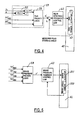
- Fig. 4 which includes the total desired rear steering angle generating unit 59, the rear steering feedback control law 62, the rear steering actuator 101 and the rear steering angle sensor 40. Where 101 and 40 are part of the vehicle 42.
- the total desired rear steering angle ⁇ r * t calculated by feeding into the unit 59 the desired rear steering angle ⁇ RSC * for achieving roll stability control, ⁇ YsC * for achieving yaw stability control and ⁇ RiF * for achieving coordination between front steering and rear steering.
- This total ⁇ r * t together with the measured rear steering angle ⁇ r is then fed back to the rear steering feedback control law unit 60.
- This feedback control unit calculates the control command to drive the RWS actuator.
- the rear steering control command can be calculated as in a PID controller: where K SP , K Sl , and K SD are the control gains.
- Controller 26 has a rollover control law block 52, which represents the determination of a roll condition or likelihood of rollover. This may be done by calculating a roll angle of the vehicle. Based on the inputs from certain of the sensors 28 through 40 referred to as a rollover sensor, the controller 26 determines the presence or likelihood of a roll condition.
- block 52 compares the moment to prevent rollover with the moments being provided at the brake system and the rear steering wheel system and determining a brake pressure signal and a rear wheel steering signal in response to the distribution.
- Controller 26 also includes brake pressure priority logic 56 and rear wheel steering priority logic 58.
- Brake pressure priority logic 56 receives a brake pressure signal from rolling moment distribution calculator 54.
- Rear wheel steering priority logic 58 receives a rear wheel steering signal from rolling moment distribution calculator 54.
- Brake pressure priority logic 56 is also coupled to anti-lock brake controller 44, traction control system controller 46, and YSC controller 48. Each of the systems including rollover control systems may operate the brakes of the vehicle. Brake pressure priority logic 56 determines an amount of braking for the individual wheels in accordance with a hierarchical ranking system. The ranking system is preferably experimentally determined and based on the overall dynamics of the vehicle. Therefore, from one vehicle type to the next, this priority scheme may be changed.
- Brake pressure priority logic 56 may also act to maximize the amount of desired control from various systems.
- the rear wheel steering priority logic 58 is coupled to front wheel steering and rear wheel steering coordinator 50 and YSC controller 48. Both of these systems control the operation of the steering system of the vehicle and more specifically the rear steering system of the vehicle.
- the rear wheel system or steering priority logic 58 is controlled and in a hierarchical fashion in a similar manner to that of brake pressure priority logic 56. That is, the rear wheel steering priority logic 58 may be experimentally determined to provide the desired amount of control for the various systems coupled thereto including rollover control system 24.
- Brake pressure priority logic 56 and rear wheel steering priority logic 58 are coupled to brake and steering system 42 through a respective brake pressure controller 60 and a rear wheel steering controller 62.
- the brake pressure controller 60 and rear wheel system controller 62 generate a respective rear wheel actuator signal and brake actuator signal which are used to trigger the desired amount of braking and rear wheel steering control.
- the brake actuator control signal may provide a signal for the brakes of each of the four corners of the vehicle.
- Fig. 5 shows the closed loop brake control system, which includes the total desired brake pressure generating mechanism (unit 58), the brake pressure feedback control law 60, the brake actuator 201 and the wheel speed sensor 205. Where 201 and 205 are part of the vehicle 42.
- the desired pressure amount ⁇ p RSC for rollover stability control, the desired pressure amount ⁇ p YSC for yaw stability control, the desired pressure amount ⁇ p TCS for traction control and the desired pressure amount ⁇ p ABS for anti-lock braking are fed into the brake pressure priority block 58, and a final desired brake pressure p* is calculated.
- This desired brake pressure is then further fed into a brake pressure feedback controller, together with the measured wheel speed sensor signals, to generate feedback control signals for the brake actuators.
- the brake closed loop system shown in Fig. 5 can be modified to the system shown in Fig. 6.
- This system includes unit 58, unit 60, the brake actuator 201, the wheel speed sensor 205 and the brake pressure sensor 210. 201, 205 and 210 are part of the vehicle 42.
- the feedback control law 60 command the hardware to achieving pressure command following.
- a PID control scheme can be applied to 60: where K BP , K Bl , and K BD are the control gains.
- C 1 A mathematical formula for C 1 may also be determined.
- C 2 changes during driving.
- C 2 may depend on
- the flow chart illustrated in Figure 7 corresponds to rolling moment distribution calculator 54 of Figure 3.
- the moment to prevent rollover M R is the moment desired for controlling rollover.
- Step 64 if the desired rolling moment is less than the maximum roll moment generated through rear wheel steering ( M RWS ).
- Step 66 is executed in which the brake flag ( BRK_FLAG ) is set to zero, the rear wheel steering flag ( RWS_FLAG ) is set to 1, and the max flag ( MAX_FLAG ) is set to zero.
- block 68 is executed and will be further described below. To summarize, block 68 determines the brake pressure and rear wheel steering angle for the vehicle. roll in block 74, this is sufficient.
- block 78 is executed in which the brake flag is set to one, the rear wheel steering flag is set to one, and the max flag is set to one.
- the max flag is used to trigger the priority system into maximizing the brake force and rear wheel steering angle to prevent rollover of the vehicle. Based on these priorities set by the flags mentioned in block 66, 72, 76, and 78, the brake pressure and rear wheel steering of the system is calculated.
- step 82 is executed in which the maximum pressure and maximum steering wheel angle is provided at the output and used to control the brake pressure control and the rear wheel steering angle of the vehicle.
- block 84 is executed in which the conditions of both the brake flag and rear wheel steering flag are determined.
- step 86 is executed in which the amount or proportion of roll moment provided by the brake pressure and rear steering angle are determined.
- block 70 is executed.
- Block 72 is executed in which the brake flag is set to 1.
- the rear wheel steering flag is set to zero, and the max flag is set to zero.
- block 68 is executed in which the brake pressure at rear wheel steering angles are computed.
- block 74 the sum of the moment provided by the rear wheel steering system and the moment provided by the braking system is added together and the sum is compared to the total moment to prevent roll. If the total moment to prevent roll is less than the sum of the moment provided by the rear wheel steering system and the brake system, then block 76 is executed in which the brake flag is set to 1, the rear wheel steering flag is set to 1, and the max flag is set to zero.
- ⁇ RSC * C 2 * M R * RWS_FLAG
- the brake pressures and the rear steering angles are provided to a distribution block 90 and are thus provided to the particular brake system or steering system to effectuate the desired amount of control.
- these systems will continuously update to change the desired amount of control based on the various systems.
- various types of steering control may be performed depending on the vehicle characteristics and the steering system.
- a rack system may be controlled to provide a desired change in the rear steering angle temporarily to prevent rollover while leaving the front wheels unchanged.
- the direction of the front wheels could also be change when the rear direction is changed.
- the relative steering angle between the rear wheels may be changed in response to detected roll without changing the position or controlling the position of the front wheels. This may be done by independent control of the rear wheels or simultaneous control of the rear wheels. This may also be done in combination with a desirable amount of brake control.
- the longitudinal acceleration sensor and a pitch rate sensor may be incorporated into the above tyre force vector determination. These sensors may be used as a verification, as well as, an integral part of the calculations.
- the pitch rate or the longitudinal acceleration or both can be used to construct a vehicle pitch angle estimate. This estimate along with its derivative can be used to improve the calculation of the vehicle roll angle.
Landscapes
- Engineering & Computer Science (AREA)
- Transportation (AREA)
- Mechanical Engineering (AREA)
- Regulating Braking Force (AREA)
- Steering Control In Accordance With Driving Conditions (AREA)
- Control Of Driving Devices And Active Controlling Of Vehicle (AREA)
Applications Claiming Priority (2)
| Application Number | Priority Date | Filing Date | Title |
|---|---|---|---|
| US09/789,656 US6799092B2 (en) | 2001-02-21 | 2001-02-21 | Rollover stability control for an automotive vehicle using rear wheel steering and brake control |
| US789656 | 2001-02-21 |
Publications (4)
| Publication Number | Publication Date |
|---|---|
| EP1234741A2 true EP1234741A2 (fr) | 2002-08-28 |
| EP1234741A3 EP1234741A3 (fr) | 2003-10-08 |
| EP1234741B1 EP1234741B1 (fr) | 2004-12-01 |
| EP1234741B2 EP1234741B2 (fr) | 2008-02-20 |
Family
ID=25148285
Family Applications (1)
| Application Number | Title | Priority Date | Filing Date |
|---|---|---|---|
| EP02100029A Expired - Lifetime EP1234741B2 (fr) | 2001-02-21 | 2002-01-17 | Commande de stabilité anti-renversement pour un véhicule automobile |
Country Status (3)
| Country | Link |
|---|---|
| US (1) | US6799092B2 (fr) |
| EP (1) | EP1234741B2 (fr) |
| DE (1) | DE60202086T3 (fr) |
Cited By (13)
| Publication number | Priority date | Publication date | Assignee | Title |
|---|---|---|---|---|
| EP1388474A3 (fr) * | 2002-08-05 | 2004-04-28 | Ford Global Technologies, LLC | Système et procédé pour déterminer une quantité de contrôle d'opération d'un système de contrôle anti-roulis |
| GB2398845A (en) * | 2003-02-26 | 2004-09-01 | Ford Global Tech Llc | A system and method for controlling a safety system of a motor vehicle |
| EP1470978A1 (fr) * | 2003-04-22 | 2004-10-27 | Continental Aktiengesellschaft | Procédé et dispositif de détection de l'état de marche |
| US6961648B2 (en) | 2002-08-05 | 2005-11-01 | Ford Motor Company | System and method for desensitizing the activation criteria of a rollover control system |
| US6963797B2 (en) | 2002-08-05 | 2005-11-08 | Ford Global Technologies, Llc | System and method for determining an amount of control for operating a rollover control system |
| US7140619B2 (en) * | 2001-05-24 | 2006-11-28 | Ford Global Technologies, Llc | Roll over stability control for an automotive vehicle having an active suspension |
| GB2441423A (en) * | 2006-08-30 | 2008-03-05 | Ford Global Tech Llc | A Method of Operating an Integrated Control System foreffecting Stability Control of a Motor Vehicle |
| WO2008040889A1 (fr) * | 2006-10-06 | 2008-04-10 | Renault S.A.S. | Procede et systeme de controle d'un vehicule equipe d'un systeme de freinage pilote et d'un systeme quatre roues directrices |
| FR2908727A1 (fr) * | 2006-11-21 | 2008-05-23 | Renault Sas | Syteme et procede de commande de braquage des roues arriere d'un vihicule automobile muni de quatre roues directrices |
| US7430468B2 (en) | 2002-08-05 | 2008-09-30 | Ford Global Technologies, Llc | System and method for sensitizing the activation criteria of a rollover control system |
| EP1529718B2 (fr) † | 2003-11-06 | 2009-08-12 | Bayerische Motoren Werke Aktiengesellschaft | Véhicule automobile avec des roues avant dirigeables et une fonction de braquage des roues arrières |
| CN103101538A (zh) * | 2011-11-10 | 2013-05-15 | 通用汽车环球科技运作有限责任公司 | 驱动轮扭矩估计系统和方法 |
| US11491970B2 (en) * | 2020-02-11 | 2022-11-08 | GM Global Technology Operations LLC | Architecture and methodology for integrated wheel and body dynamic controls with standard stability features |
Families Citing this family (72)
| Publication number | Priority date | Publication date | Assignee | Title |
|---|---|---|---|---|
| US6834218B2 (en) | 2001-11-05 | 2004-12-21 | Ford Global Technologies, Llc | Roll over stability control for an automotive vehicle |
| US6904350B2 (en) | 2000-09-25 | 2005-06-07 | Ford Global Technologies, Llc | System for dynamically determining the wheel grounding and wheel lifting conditions and their applications in roll stability control |
| US7233236B2 (en) | 2000-09-25 | 2007-06-19 | Ford Global Technologies, Llc | Passive wheel lift identification for an automotive vehicle using operating input torque to wheel |
| US7109856B2 (en) | 2000-09-25 | 2006-09-19 | Ford Global Technologies, Llc | Wheel lifted and grounded identification for an automotive vehicle |
| US6356188B1 (en) | 2000-09-25 | 2002-03-12 | Ford Global Technologies, Inc. | Wheel lift identification for an automotive vehicle |
| US7132937B2 (en) | 2000-09-25 | 2006-11-07 | Ford Global Technologies, Llc | Wheel lift identification for an automotive vehicle using passive and active detection |
| US7146260B2 (en) | 2001-04-24 | 2006-12-05 | Medius, Inc. | Method and apparatus for dynamic configuration of multiprocessor system |
| US10298735B2 (en) | 2001-04-24 | 2019-05-21 | Northwater Intellectual Property Fund L.P. 2 | Method and apparatus for dynamic configuration of a multiprocessor health data system |
| JP3608050B2 (ja) * | 2001-07-24 | 2005-01-05 | トヨタ自動車株式会社 | ロールオーバ判別装置 |
| US6654674B2 (en) | 2001-11-21 | 2003-11-25 | Ford Global Technologies, Llc | Enhanced system for yaw stability control system to include roll stability control function |
| US6556908B1 (en) | 2002-03-04 | 2003-04-29 | Ford Global Technologies, Inc. | Attitude sensing system for an automotive vehicle relative to the road |
| US7178049B2 (en) | 2002-04-24 | 2007-02-13 | Medius, Inc. | Method for multi-tasking multiple Java virtual machines in a secure environment |
| DE10226599A1 (de) * | 2002-06-14 | 2003-12-24 | Still Wagner Gmbh & Co Kg | Verfahren zum Steuern mindestens einer Bewegung eines Flurförderzeugs |
| DE10234593B4 (de) * | 2002-07-30 | 2010-08-26 | Robert Bosch Gmbh | Vorrichtung zur Erkennung eines Fahrzeugüberschlags |
| US7194351B2 (en) | 2002-08-01 | 2007-03-20 | Ford Global Technologies, Llc | System and method for determining a wheel departure angle for a rollover control system |
| US7079928B2 (en) | 2002-08-01 | 2006-07-18 | Ford Global Technologies, Llc | System and method for determining a wheel departure angle for a rollover control system with respect to road roll rate and loading misalignment |
| US6941205B2 (en) | 2002-08-01 | 2005-09-06 | Ford Global Technologies, Llc. | System and method for deteching roll rate sensor fault |
| US7302331B2 (en) | 2002-08-01 | 2007-11-27 | Ford Global Technologies, Inc. | Wheel lift identification for an automotive vehicle |
| US7085639B2 (en) | 2002-08-01 | 2006-08-01 | Ford Global Technologies, Llc | System and method for characterizing the road bank for vehicle roll stability control |
| US7003389B2 (en) | 2002-08-01 | 2006-02-21 | Ford Global Technologies, Llc | System and method for characterizing vehicle body to road angle for vehicle roll stability control |
| US20040024505A1 (en) | 2002-08-05 | 2004-02-05 | Salib Albert Chenouda | System and method for operating a rollover control system in a transition to a rollover condition |
| US7085642B2 (en) | 2002-08-05 | 2006-08-01 | Ford Global Technologies, Llc | Method and system for correcting sensor offsets |
| US20040024504A1 (en) | 2002-08-05 | 2004-02-05 | Salib Albert Chenouda | System and method for operating a rollover control system during an elevated condition |
| WO2004074059A2 (fr) * | 2003-02-20 | 2004-09-02 | Continental Teves Ag & Co. Ohg | Procede et systeme pour regler la stabilite a la conduite d'un vehicule et utilisation dudit systeme |
| US9162656B2 (en) | 2003-02-26 | 2015-10-20 | Ford Global Technologies, Llc | Active driven wheel lift identification for an automotive vehicle |
| US7653471B2 (en) | 2003-02-26 | 2010-01-26 | Ford Global Technologies, Llc | Active driven wheel lift identification for an automotive vehicle |
| US7239949B2 (en) | 2003-02-26 | 2007-07-03 | Ford Global Technologies, Llc | Integrated sensing system |
| US7136731B2 (en) | 2003-06-11 | 2006-11-14 | Ford Global Technologies, Llc | System for determining vehicular relative roll angle during a potential rollover event |
| US7164980B1 (en) * | 2003-09-04 | 2007-01-16 | Kelsey-Hayes Company | Control architecture and method for integrating vehicle stability control functions with rear wheel steering control functions in a motor vehicle |
| JP4391785B2 (ja) * | 2003-09-30 | 2009-12-24 | 三菱ふそうトラック・バス株式会社 | 車両のロールオーバ抑制制御装置 |
| US6856868B1 (en) | 2003-10-24 | 2005-02-15 | Ford Global Technologies, Llc | Kinetic energy density rollover detective sensing algorithm |
| US7321825B2 (en) * | 2003-10-24 | 2008-01-22 | Ford Global Technologies, Llc | Method and apparatus for determining vehicle operating conditions and providing a warning or intervention in response to the conditions |
| US7197388B2 (en) * | 2003-11-06 | 2007-03-27 | Ford Global Technologies, Llc | Roll stability control system for an automotive vehicle using an external environmental sensing system |
| DE10356827B4 (de) * | 2003-12-05 | 2019-05-23 | Robert Bosch Gmbh | Kippstabilisierungssystem mit Berücksichtigung des Lenkwinkels |
| US6904351B1 (en) * | 2004-03-17 | 2005-06-07 | Delphi Technologies, Inc. | Operating a vehicle control system |
| US7831354B2 (en) * | 2004-03-23 | 2010-11-09 | Continental Teves, Inc. | Body state estimation of a vehicle |
| US7031816B2 (en) * | 2004-03-23 | 2006-04-18 | Continental Teves, Inc. | Active rollover protection |
| US7502675B2 (en) | 2004-04-01 | 2009-03-10 | Delphi Technologies, Inc. | Feedforward control of motor vehicle roll angle |
| US7369927B2 (en) * | 2004-04-02 | 2008-05-06 | Continental Teves, Inc. | Active rollover protection utilizing steering angle rate map |
| US7308350B2 (en) | 2004-05-20 | 2007-12-11 | Ford Global Technologies, Llc | Method and apparatus for determining adaptive brake gain parameters for use in a safety system of an automotive vehicle |
| US7451032B2 (en) | 2004-06-02 | 2008-11-11 | Ford Global Technologies, Llc | System and method for determining desired yaw rate and lateral velocity for use in a vehicle dynamic control system |
| US7191047B2 (en) | 2004-09-27 | 2007-03-13 | Delphi Technologies, Inc. | Motor vehicle control using a dynamic feedforward approach |
| DE602004012903T2 (de) * | 2004-09-29 | 2009-04-09 | Pirelli Tyre S.P.A. | Verfahren und system zur bestimmung des schräglauf-winkels eines reifens während des fahrens eines fahrzeugs |
| US7640081B2 (en) | 2004-10-01 | 2009-12-29 | Ford Global Technologies, Llc | Roll stability control using four-wheel drive |
| US7668645B2 (en) | 2004-10-15 | 2010-02-23 | Ford Global Technologies | System and method for dynamically determining vehicle loading and vertical loading distance for use in a vehicle dynamic control system |
| US7715965B2 (en) | 2004-10-15 | 2010-05-11 | Ford Global Technologies | System and method for qualitatively determining vehicle loading conditions |
| US7239952B2 (en) * | 2004-12-08 | 2007-07-03 | Continental Teves, Inc. | Reduced order parameter identification for vehicle rollover control system |
| US7660654B2 (en) | 2004-12-13 | 2010-02-09 | Ford Global Technologies, Llc | System for dynamically determining vehicle rear/trunk loading for use in a vehicle control system |
| US7557697B2 (en) * | 2005-02-22 | 2009-07-07 | Continental Teves, Inc. | System to measure wheel liftoff |
| US7480547B2 (en) | 2005-04-14 | 2009-01-20 | Ford Global Technologies, Llc | Attitude sensing system for an automotive vehicle relative to the road |
| US7590481B2 (en) | 2005-09-19 | 2009-09-15 | Ford Global Technologies, Llc | Integrated vehicle control system using dynamically determined vehicle conditions |
| US7600826B2 (en) | 2005-11-09 | 2009-10-13 | Ford Global Technologies, Llc | System for dynamically determining axle loadings of a moving vehicle using integrated sensing system and its application in vehicle dynamics controls |
| US8121758B2 (en) | 2005-11-09 | 2012-02-21 | Ford Global Technologies | System for determining torque and tire forces using integrated sensing system |
| US7876238B2 (en) * | 2005-12-22 | 2011-01-25 | The Boeing Company | Methods and systems for displaying procedure information |
| DE102006018029A1 (de) * | 2006-04-19 | 2007-10-25 | Robert Bosch Gmbh | Vorrichtung und Verfahren zur Ansteuerung von Personenschutzmitteln |
| WO2007129750A1 (fr) * | 2006-05-10 | 2007-11-15 | Toyota Jidosha Kabushiki Kaisha | Dispositif de controle de direction de vehicule |
| US7571039B2 (en) * | 2006-08-08 | 2009-08-04 | Gm Global Technology Operations, Inc. | Vehicle yaw/roll stability control with semi-active suspension |
| US8744689B2 (en) * | 2007-07-26 | 2014-06-03 | Hitachi, Ltd. | Drive controlling apparatus for a vehicle |
| US7917274B2 (en) * | 2007-10-19 | 2011-03-29 | Advics Co., Ltd. | Method and apparatus for vehicle sway detection and reduction |
| JP4997065B2 (ja) * | 2007-10-29 | 2012-08-08 | 日立オートモティブシステムズ株式会社 | 車両制御装置 |
| KR20090107334A (ko) * | 2008-04-08 | 2009-10-13 | 주식회사 만도 | 차량용 제동제어장치와 현가제어장치 간의 데이터통신을 통한 차고제어장치 및 그 제어방법 |
| US9358924B1 (en) | 2009-05-08 | 2016-06-07 | Eagle Harbor Holdings, Llc | System and method for modeling advanced automotive safety systems |
| JP5589872B2 (ja) * | 2011-01-31 | 2014-09-17 | 株式会社アドヴィックス | 車両の運動制御装置 |
| US9260096B2 (en) * | 2011-02-22 | 2016-02-16 | Nissin Kogyo Co., Ltd. | Brake fluid pressure control apparatus for vehicle |
| DE102011120667A1 (de) | 2011-12-09 | 2013-06-13 | Wabco Gmbh | Fahrstabilisierungsverfahren, Fahrstabbilisierungseinrichtung und Fahrzeug damit |
| US9257396B2 (en) | 2014-05-22 | 2016-02-09 | Invensas Corporation | Compact semiconductor package and related methods |
| DE102017200144B4 (de) | 2016-01-22 | 2019-05-02 | Ford Global Technologies, Llc | Rückfallbetriebsmodus für ein Verfahren für das Betreiben eines Kraftfahrzeugs mit einem aktiven Querstabilisator und einer aktiven Lenkung |
| DE102016216825A1 (de) | 2016-09-06 | 2018-03-08 | Zf Friedrichshafen Ag | Verfahren zur Stabilisierung des Fahrverhaltens eines Fahrzeuges |
| DE102017212165B4 (de) * | 2017-07-17 | 2023-11-30 | Ford Global Technologies, Llc | Neigefahrzeug |
| EP4469321A4 (fr) | 2022-02-04 | 2025-05-21 | Zimeno, Inc. DBA Monarch Tractor | Atténuation de retournement de véhicule |
| DE102023101753A1 (de) * | 2023-01-25 | 2024-07-25 | Dr. Ing. H.C. F. Porsche Aktiengesellschaft | Verfahren zum Betreiben eines aktiven Wankabstützsystems eines Kraftfahrzeugs |
| DE102023132395A1 (de) * | 2023-11-21 | 2025-05-22 | Audi Aktiengesellschaft | Vorrichtung zum Betreiben eines Fahrwerks eines zweispurigen Fahrzeugs |
Citations (3)
| Publication number | Priority date | Publication date | Assignee | Title |
|---|---|---|---|---|
| US5634698A (en) | 1994-02-19 | 1997-06-03 | Robert Bosch Gmbh | System for controlling brake pressure based on fuzzy logic using steering angle and yaw speed |
| US5869943A (en) | 1996-10-23 | 1999-02-09 | Aisin Seiki Kabushiki Kaisha | Vehicle motion control system |
| US6065558A (en) | 1997-07-01 | 2000-05-23 | Dynamotive, L.L.C. | Anti-rollover brake system |
Family Cites Families (86)
| Publication number | Priority date | Publication date | Assignee | Title |
|---|---|---|---|---|
| US2917126A (en) | 1957-04-04 | 1959-12-15 | Nolan Phillips | Driving control safety mechanism for tractors |
| US3608925A (en) | 1969-05-07 | 1971-09-28 | Peter H Murphy | Apparatus for offsetting centrifugal force affecting motor vehicles |
| US4023864A (en) | 1973-09-20 | 1977-05-17 | Lang Davis Industries, Inc. | Automatic stability control system with strain gauge sensors |
| US3972543A (en) | 1974-12-06 | 1976-08-03 | The Bendix Corporation | Combination vehicle yaw stabilizer |
| US3948567A (en) | 1975-02-12 | 1976-04-06 | The Bendix Corporation | Sway control means for a trailer |
| USRE30550E (en) | 1975-11-06 | 1981-03-24 | Durrell U. Howard | Automatic trailer sway sensing and brake applying system |
| GB1543586A (en) | 1978-07-24 | 1979-04-04 | Whitworth B | Flexible tube |
| SU816849A1 (ru) | 1979-05-07 | 1981-03-30 | Ленинградский Ордена Трудовогокрасного Знамени Сельскохозяйственныйинститут | Устройство дл предотвращени ОпРОКидыВАНи ТРАНСпОРТНОгО СРЕдСТВА |
| JPS576064A (en) | 1980-06-14 | 1982-01-12 | Kajima Corp | Vibration resistant building |
| JPS58152793A (ja) | 1982-03-05 | 1983-09-10 | ティー・シー・エム株式会社 | 運搬車両の横転防止装置 |
| US4592565A (en) | 1984-10-17 | 1986-06-03 | Leo Eagle | Apparatus for detecting an overturning moment in a moving vehicle, and jackknifing in a trailer-truck combination |
| DE3606797C2 (de) | 1986-03-01 | 2000-11-23 | Bosch Gmbh Robert | Vorrichtung und Verfahren zur Steuerung, insbesondere zur Begrenzung, der Fahrgeschwindigkeit eines Straßenfahrzeuges |
| DE3616907A1 (de) | 1986-05-20 | 1987-11-26 | Hans Prof Dr Ing Marko | Einrichtung zur regelung der drehgeschwindigkeit eines kraftfahrzeuges um die hochachse |
| JPS63116918A (ja) | 1986-11-05 | 1988-05-21 | Kayaba Ind Co Ltd | ロ−ル制御機構 |
| JPS63151539A (ja) | 1986-12-15 | 1988-06-24 | Mitsubishi Electric Corp | 車両走行制御装置 |
| JPS63203456A (ja) | 1987-02-18 | 1988-08-23 | Mazda Motor Corp | 自動車の駆動力制御装置 |
| DE3826982C2 (de) | 1987-08-10 | 2000-11-30 | Denso Corp | Hilfslenksystem verbunden mit einem Antiblockiersteuerungssystem zur Verwendung in Kraftfahrzeugen |
| JPH01101238A (ja) | 1987-10-14 | 1989-04-19 | Matsushita Electric Ind Co Ltd | 速度制御装置 |
| JP2618250B2 (ja) | 1987-12-22 | 1997-06-11 | 富士重工業株式会社 | トラクション制御装置 |
| DE3805589A1 (de) | 1988-02-23 | 1989-08-31 | Lucas Ind Plc | Verfahren und vorrichtung zum steuern einer bremsanlage fuer schwerfahrzeuge |
| DE3815938C2 (de) | 1988-05-10 | 1996-09-19 | Bayerische Motoren Werke Ag | Beschleunigungs-Sensor für Fahrzeuge |
| US4898431A (en) | 1988-06-15 | 1990-02-06 | Aisin Seiki Kabushiki Kaisha | Brake controlling system |
| JP2768710B2 (ja) | 1988-09-17 | 1998-06-25 | ローベルト・ボッシュ・ゲゼルシャフト・ミット・ベシュレンクテル・ハフツング | 車両の搭乗者を保護する保護装置を起動する装置 |
| JP2600876B2 (ja) | 1988-12-26 | 1997-04-16 | 日産自動車株式会社 | 車両の旋回制御装置 |
| US4998593A (en) | 1989-03-31 | 1991-03-12 | Aisin Seiki Kabushiki Kaisha | Steering and brake controlling system |
| JP2623840B2 (ja) | 1989-07-11 | 1997-06-25 | 日産自動車株式会社 | 車両の旋回挙動制御装置 |
| JP2572849B2 (ja) | 1989-07-13 | 1997-01-16 | 日産自動車株式会社 | 車両の旋回挙動制御装置 |
| JP2696416B2 (ja) | 1990-04-26 | 1998-01-14 | 稚晴 中村 | 車の横転防止装置 |
| JP2679415B2 (ja) | 1990-12-21 | 1997-11-19 | 日産自動車株式会社 | 車両の制動力左右配分制御装置 |
| DE4201146C2 (de) | 1991-01-18 | 2003-01-30 | Hitachi Ltd | Vorrichtung zur Steuerung des Kraftfahrzeugverhaltens |
| GB2257403A (en) | 1991-07-06 | 1993-01-13 | Gloster Saro Ltd | Road vehicle stability indicating system. |
| JPH0516699A (ja) | 1991-07-11 | 1993-01-26 | Matsushita Electric Ind Co Ltd | 安全走行装置 |
| US5335176A (en) | 1991-12-02 | 1994-08-02 | Koyo Seiko Co., Ltd. | Safety system for vehicles |
| JPH05254406A (ja) | 1992-03-13 | 1993-10-05 | Mitsubishi Motors Corp | 車両用ブレーキシステム |
| JPH0616117A (ja) | 1992-06-30 | 1994-01-25 | Honda Motor Co Ltd | 車両における車輪前後力制御方法 |
| DE4227886A1 (de) | 1992-08-22 | 1994-02-24 | Sel Alcatel Ag | Neigungsgeber für ein Fahrzeug mit einem Aufbau |
| DE4228893B4 (de) | 1992-08-29 | 2004-04-08 | Robert Bosch Gmbh | System zur Beeinflussung der Fahrdynamik eines Kraftfahrzeugs |
| JPH06278586A (ja) | 1993-03-25 | 1994-10-04 | Mitsubishi Motors Corp | 車両のブレーキ装置 |
| JPH06312612A (ja) | 1993-04-30 | 1994-11-08 | Isuzu Motors Ltd | 車両の横転警報装置 |
| DE4323712C2 (de) | 1993-07-15 | 1997-12-11 | Heidenhain Gmbh Dr Johannes | Lichtelektrische Längen- oder Winkelmeßeinrichtung |
| DE4335979A1 (de) | 1993-10-21 | 1995-04-27 | Telefunken Microelectron | Sicherheits-Management-System (SMS) |
| DE69506741T2 (de) * | 1994-01-14 | 1999-09-02 | Matsushita Electric Industrial Co. | Vorrichtung zum Steuern eines Lenkwinkels |
| JP3303500B2 (ja) | 1994-02-02 | 2002-07-22 | トヨタ自動車株式会社 | 車両の挙動制御装置 |
| US5446658A (en) | 1994-06-22 | 1995-08-29 | General Motors Corporation | Method and apparatus for estimating incline and bank angles of a road surface |
| US5610575A (en) | 1994-08-25 | 1997-03-11 | Automotive Systems Laboratory, Inc. | Method and system for detecting vehicle roll-over |
| JPH0880825A (ja) | 1994-09-12 | 1996-03-26 | Toyota Motor Corp | 車両制動装置 |
| DE19515050A1 (de) | 1994-11-25 | 1996-05-30 | Teves Gmbh Alfred | Verfahren zur Fahrstabilitätsregelschaltung mit Steuerung über Druckgradienten |
| US5732379A (en) | 1994-11-25 | 1998-03-24 | Itt Automotive Europe Gmbh | Brake system for a motor vehicle with yaw moment control |
| US5732378A (en) | 1994-11-25 | 1998-03-24 | Itt Automotive Europe Gmbh | Method for determining a wheel brake pressure |
| JP3042360B2 (ja) | 1995-04-13 | 2000-05-15 | 日本ビクター株式会社 | 磁気ヘッド反転装置 |
| JP3161283B2 (ja) | 1995-06-15 | 2001-04-25 | トヨタ自動車株式会社 | 車両の横加速度検出装置 |
| DE19529539A1 (de) | 1995-08-11 | 1997-02-13 | Man Nutzfahrzeuge Ag | Verfahren zur ON-BOARD-Ermittlung von fahrdynamischen Sicherheitsreserven von Nutzfahrzeugen |
| JP3248411B2 (ja) | 1995-10-11 | 2002-01-21 | トヨタ自動車株式会社 | 車輌の挙動制御装置 |
| JP3248413B2 (ja) | 1995-10-18 | 2002-01-21 | トヨタ自動車株式会社 | 車輌の挙動制御装置 |
| JP3627325B2 (ja) | 1995-11-17 | 2005-03-09 | アイシン精機株式会社 | 車両の運動制御装置 |
| AUPN786796A0 (en) | 1996-02-05 | 1996-02-29 | Verward Pty Ltd (trading as Brooks Merchants) | Vehicle seat |
| US5809434A (en) | 1996-04-26 | 1998-09-15 | Ford Global Technologies, Inc. | Method and apparatus for dynamically determically determining an operating state of a motor vehicle |
| US5742918A (en) | 1996-04-26 | 1998-04-21 | Ford Global Technologies, Inc. | Method and apparatus for dynamically compensating a lateral acceleration of a motor vehicle |
| JPH09315277A (ja) | 1996-05-31 | 1997-12-09 | Unisia Jecs Corp | 車両運動制御装置 |
| EP0907526A4 (fr) | 1996-06-24 | 2001-01-03 | Breed Automotive Tech | Unite de commande pour dispositif de securite pour vehicule |
| JP2877084B2 (ja) | 1996-07-09 | 1999-03-31 | 三菱自動車工業株式会社 | 制動力制御装置 |
| US5707117A (en) | 1996-07-19 | 1998-01-13 | General Motors Corporation | Active brake control diagnostic |
| DE19655388B4 (de) | 1996-08-16 | 2008-08-14 | Daimler Ag | Fahrdynamikregelungssystem und Verfahren |
| JPH10129439A (ja) | 1996-10-25 | 1998-05-19 | Aisin Seiki Co Ltd | 車両の運動制御装置 |
| US5825284A (en) | 1996-12-10 | 1998-10-20 | Rollover Operations, Llc | System and method for the detection of vehicle rollover conditions |
| JP3269421B2 (ja) | 1997-04-04 | 2002-03-25 | 三菱自動車工業株式会社 | 車両の自動減速制御装置 |
| JPH10329682A (ja) | 1997-06-03 | 1998-12-15 | Mitsubishi Motors Corp | 車両の横転防止装置 |
| JP3982011B2 (ja) | 1997-06-24 | 2007-09-26 | 三菱ふそうトラック・バス株式会社 | 車両の横転防止装置 |
| DE19751935A1 (de) | 1997-11-22 | 1999-05-27 | Bosch Gmbh Robert | Verfahren und Vorrichtung zur Ermittlung einer die Schwerpunktshöhe eines Fahrzeuges beschreibenden Größe |
| DE19751839A1 (de) | 1997-11-22 | 1999-05-27 | Bosch Gmbh Robert | Verfahren und Vorrichtung zur Erkennung einer Kipptendenz eines Fahrzeuges |
| DE19751891A1 (de) | 1997-11-22 | 1999-05-27 | Bosch Gmbh Robert | Verfahren und Vorrichtung zur Stabilisierung eines Fahrzeuges bei Kipptendenz |
| DE19751867A1 (de) | 1997-11-22 | 1999-05-27 | Bosch Gmbh Robert | Verfahren und Vorrichtung zur Erkennung einer Kipptendenz eines Fahrzeuges |
| DE19751925A1 (de) | 1997-11-22 | 1999-05-27 | Bosch Gmbh Robert | Verfahren und Vorrichtung zur Erkennung einer Kipptendenz eines Fahrzeuges |
| JPH11170992A (ja) | 1997-12-10 | 1999-06-29 | Mitsubishi Motors Corp | 車両の横転防止装置 |
| EP1040033B1 (fr) | 1997-12-16 | 2005-04-06 | Continental Teves AG & Co. oHG | Procede pour accroitre la stabilite au capotage d'un vehicule |
| DE19802041A1 (de) | 1998-01-21 | 1999-07-22 | Bosch Gmbh Robert | Verfahren und Vorrichtung zur Stabilisierung eines Fahrzeuges im Sinne einer Umkippvermeidung |
| US6038495A (en) | 1998-02-06 | 2000-03-14 | Delco Electronics Corporation | Vehicle rollover sensing using short-term integration |
| US6002974A (en) | 1998-02-06 | 1999-12-14 | Delco Electronics Corporation | Vehicle rollover sensing using extended kalman filter |
| US6002975A (en) | 1998-02-06 | 1999-12-14 | Delco Electronics Corporation | Vehicle rollover sensing |
| JPH11254992A (ja) | 1998-03-09 | 1999-09-21 | Mitsubishi Motors Corp | 車両の横転傾向判定装置およびその装置を用いた横転防止装置 |
| JP3436119B2 (ja) | 1998-03-11 | 2003-08-11 | トヨタ自動車株式会社 | 車体ロール抑制制御装置 |
| KR100572500B1 (ko) | 1998-04-07 | 2006-04-24 | 로베르트 보쉬 게엠베하 | 차량의 안정화 방법 및 장치 |
| JP3369467B2 (ja) | 1998-04-24 | 2003-01-20 | 日野自動車株式会社 | 車両の重心高さの推定演算装置 |
| JP3345346B2 (ja) | 1998-04-24 | 2002-11-18 | 日野自動車株式会社 | 車両の重心高さの推定演算装置 |
| DE19918597C2 (de) † | 1999-04-23 | 2001-03-08 | Deutsch Zentr Luft & Raumfahrt | Verfahren zur Reduktion der Kippgefahr von Straßenfahrzeugen |
| US6263261B1 (en) * | 1999-12-21 | 2001-07-17 | Ford Global Technologies, Inc. | Roll over stability control for an automotive vehicle |
-
2001
- 2001-02-21 US US09/789,656 patent/US6799092B2/en not_active Expired - Lifetime
-
2002
- 2002-01-17 EP EP02100029A patent/EP1234741B2/fr not_active Expired - Lifetime
- 2002-01-17 DE DE60202086T patent/DE60202086T3/de not_active Expired - Lifetime
Patent Citations (3)
| Publication number | Priority date | Publication date | Assignee | Title |
|---|---|---|---|---|
| US5634698A (en) | 1994-02-19 | 1997-06-03 | Robert Bosch Gmbh | System for controlling brake pressure based on fuzzy logic using steering angle and yaw speed |
| US5869943A (en) | 1996-10-23 | 1999-02-09 | Aisin Seiki Kabushiki Kaisha | Vehicle motion control system |
| US6065558A (en) | 1997-07-01 | 2000-05-23 | Dynamotive, L.L.C. | Anti-rollover brake system |
Cited By (19)
| Publication number | Priority date | Publication date | Assignee | Title |
|---|---|---|---|---|
| US7140619B2 (en) * | 2001-05-24 | 2006-11-28 | Ford Global Technologies, Llc | Roll over stability control for an automotive vehicle having an active suspension |
| EP1388474A3 (fr) * | 2002-08-05 | 2004-04-28 | Ford Global Technologies, LLC | Système et procédé pour déterminer une quantité de contrôle d'opération d'un système de contrôle anti-roulis |
| US7430468B2 (en) | 2002-08-05 | 2008-09-30 | Ford Global Technologies, Llc | System and method for sensitizing the activation criteria of a rollover control system |
| US6961648B2 (en) | 2002-08-05 | 2005-11-01 | Ford Motor Company | System and method for desensitizing the activation criteria of a rollover control system |
| US6963797B2 (en) | 2002-08-05 | 2005-11-08 | Ford Global Technologies, Llc | System and method for determining an amount of control for operating a rollover control system |
| GB2398845A (en) * | 2003-02-26 | 2004-09-01 | Ford Global Tech Llc | A system and method for controlling a safety system of a motor vehicle |
| US6915193B2 (en) | 2003-02-26 | 2005-07-05 | Ford Global Technologies, Llc | Method for determining a longitudinal vehicle velocity by compensating individual wheel speeds using pitch attitude |
| GB2398845B (en) * | 2003-02-26 | 2005-12-14 | Ford Global Tech Llc | A system and method for controlling a safety system of a motor vehicle |
| US7209818B2 (en) | 2003-04-22 | 2007-04-24 | Continental Aktiengesellschaft | Method and arrangement for detecting a driving state |
| EP1470978A1 (fr) * | 2003-04-22 | 2004-10-27 | Continental Aktiengesellschaft | Procédé et dispositif de détection de l'état de marche |
| EP1529718B2 (fr) † | 2003-11-06 | 2009-08-12 | Bayerische Motoren Werke Aktiengesellschaft | Véhicule automobile avec des roues avant dirigeables et une fonction de braquage des roues arrières |
| GB2441423A (en) * | 2006-08-30 | 2008-03-05 | Ford Global Tech Llc | A Method of Operating an Integrated Control System foreffecting Stability Control of a Motor Vehicle |
| WO2008040889A1 (fr) * | 2006-10-06 | 2008-04-10 | Renault S.A.S. | Procede et systeme de controle d'un vehicule equipe d'un systeme de freinage pilote et d'un systeme quatre roues directrices |
| FR2906779A1 (fr) * | 2006-10-06 | 2008-04-11 | Renault Sas | Procede et systeme de controle d'un vehicule equipe d'un systeme de freinage pilote et d'un systeme quatre roues directrices. |
| FR2908727A1 (fr) * | 2006-11-21 | 2008-05-23 | Renault Sas | Syteme et procede de commande de braquage des roues arriere d'un vihicule automobile muni de quatre roues directrices |
| WO2008062122A1 (fr) * | 2006-11-21 | 2008-05-29 | Renault S.A.S. | Systeme et procede de commande de braquage des roues arriere d'un vehicule automobile muni de quatre roues directrices |
| CN103101538A (zh) * | 2011-11-10 | 2013-05-15 | 通用汽车环球科技运作有限责任公司 | 驱动轮扭矩估计系统和方法 |
| CN103101538B (zh) * | 2011-11-10 | 2016-08-03 | 通用汽车环球科技运作有限责任公司 | 驱动轮扭矩估计系统和方法 |
| US11491970B2 (en) * | 2020-02-11 | 2022-11-08 | GM Global Technology Operations LLC | Architecture and methodology for integrated wheel and body dynamic controls with standard stability features |
Also Published As
| Publication number | Publication date |
|---|---|
| EP1234741B1 (fr) | 2004-12-01 |
| DE60202086T2 (de) | 2005-04-07 |
| US20020139599A1 (en) | 2002-10-03 |
| US6799092B2 (en) | 2004-09-28 |
| EP1234741A3 (fr) | 2003-10-08 |
| EP1234741B2 (fr) | 2008-02-20 |
| DE60202086T3 (de) | 2008-12-24 |
| DE60202086D1 (de) | 2005-01-05 |
Similar Documents
| Publication | Publication Date | Title |
|---|---|---|
| EP1234741B1 (fr) | Commande de stabilité anti-renversement pour un véhicule automobile | |
| US6834218B2 (en) | Roll over stability control for an automotive vehicle | |
| US6662898B1 (en) | Tire side slip angle control for an automotive vehicle using steering actuators | |
| US6338012B2 (en) | Roll over stability control for an automotive vehicle | |
| US6529803B2 (en) | Roll over stability control for an automotive vehicle having rear wheel steering | |
| US7140619B2 (en) | Roll over stability control for an automotive vehicle having an active suspension | |
| US6654674B2 (en) | Enhanced system for yaw stability control system to include roll stability control function | |
| US6593849B2 (en) | Wheel lift identification for an automotive vehicle | |
| US7647148B2 (en) | Roll stability control system for an automotive vehicle using coordinated control of anti-roll bar and brakes | |
| JP4942296B2 (ja) | 車両の安定性を高める方法 | |
| US7143864B2 (en) | Yaw control for an automotive vehicle using steering actuators | |
| US7451032B2 (en) | System and method for determining desired yaw rate and lateral velocity for use in a vehicle dynamic control system | |
| US8775048B2 (en) | Method and apparatus for determining a reference vehicle velocity and a rear wheel speed in a vehicle having three speed sensors | |
| US7600826B2 (en) | System for dynamically determining axle loadings of a moving vehicle using integrated sensing system and its application in vehicle dynamics controls | |
| US6631317B2 (en) | Attitude sensing system for an automotive vehicle | |
| EP1386808B1 (fr) | Système et procédé caractérisant l'angle entre la carrosserie de véhicule et la route pour contrôle de roulis de véhicule | |
| US6840343B2 (en) | Tire side slip angle control for an automotive vehicle using steering peak seeking actuators | |
| US20240278755A1 (en) | Apparatus and method for controlling brake system in case of steering system failure | |
| JP2003231429A (ja) | 車両の中心対称面の両側での荷重移動を考慮した横方向力の測定値による車両の軌道へのアクション | |
| Brown | (73) Assignee: Ford Global Technologies, LLC, Dearborn, MI (US)(*) Notice: Subject to any disclaimer, the term of this patent is extended or adjusted under 35 |
Legal Events
| Date | Code | Title | Description |
|---|---|---|---|
| PUAI | Public reference made under article 153(3) epc to a published international application that has entered the european phase |
Free format text: ORIGINAL CODE: 0009012 |
|
| AK | Designated contracting states |
Kind code of ref document: A2 Designated state(s): AT BE CH CY DE DK ES FI FR GB GR IE IT LI LU MC NL PT SE TR |
|
| AX | Request for extension of the european patent |
Free format text: AL;LT;LV;MK;RO;SI |
|
| PUAL | Search report despatched |
Free format text: ORIGINAL CODE: 0009013 |
|
| AK | Designated contracting states |
Kind code of ref document: A3 Designated state(s): AT BE CH CY DE DK ES FI FR GB GR IE IT LI LU MC NL PT SE TR |
|
| AX | Request for extension of the european patent |
Extension state: AL LT LV MK RO SI |
|
| RIC1 | Information provided on ipc code assigned before grant |
Ipc: 7B 62D 7/15 B Ipc: 7B 60T 8/00 A |
|
| GRAP | Despatch of communication of intention to grant a patent |
Free format text: ORIGINAL CODE: EPIDOSNIGR1 |
|
| 17P | Request for examination filed |
Effective date: 20040312 |
|
| AKX | Designation fees paid |
Designated state(s): DE FR GB |
|
| GRAA | (expected) grant |
Free format text: ORIGINAL CODE: 0009210 |
|
| GRAS | Grant fee paid |
Free format text: ORIGINAL CODE: EPIDOSNIGR3 |
|
| AK | Designated contracting states |
Kind code of ref document: B1 Designated state(s): DE FR GB |
|
| PG25 | Lapsed in a contracting state [announced via postgrant information from national office to epo] |
Ref country code: FR Free format text: LAPSE BECAUSE OF NON-PAYMENT OF DUE FEES Effective date: 20041201 |
|
| REG | Reference to a national code |
Ref country code: GB Ref legal event code: FG4D |
|
| REG | Reference to a national code |
Ref country code: IE Ref legal event code: FG4D |
|
| PGFP | Annual fee paid to national office [announced via postgrant information from national office to epo] |
Ref country code: FR Payment date: 20050105 Year of fee payment: 4 |
|
| REF | Corresponds to: |
Ref document number: 60202086 Country of ref document: DE Date of ref document: 20050105 Kind code of ref document: P |
|
| PLBI | Opposition filed |
Free format text: ORIGINAL CODE: 0009260 |
|
| PLAX | Notice of opposition and request to file observation + time limit sent |
Free format text: ORIGINAL CODE: EPIDOSNOBS2 |
|
| 26 | Opposition filed |
Opponent name: DLR DEUTSCHES ZENTRUM FUER LUFT- UND RAUMFAHRT E.V Effective date: 20050831 |
|
| REG | Reference to a national code |
Ref country code: GB Ref legal event code: 732E |
|
| PLAF | Information modified related to communication of a notice of opposition and request to file observations + time limit |
Free format text: ORIGINAL CODE: EPIDOSCOBS2 |
|
| EN | Fr: translation not filed | ||
| PLBB | Reply of patent proprietor to notice(s) of opposition received |
Free format text: ORIGINAL CODE: EPIDOSNOBS3 |
|
| RAP2 | Party data changed (patent owner data changed or rights of a patent transferred) |
Owner name: FORD GLOBAL TECHNOLOGIES, LLC |
|
| RAP2 | Party data changed (patent owner data changed or rights of a patent transferred) |
Owner name: FORD GLOBAL TECHNOLOGIES, LLC |
|
| RIC2 | Information provided on ipc code assigned after grant |
Ipc: B62D 7/15 20060101ALI20071108BHEP Ipc: B60T 8/17 20060101AFI20071108BHEP |
|
| PUAH | Patent maintained in amended form |
Free format text: ORIGINAL CODE: 0009272 |
|
| STAA | Information on the status of an ep patent application or granted ep patent |
Free format text: STATUS: PATENT MAINTAINED AS AMENDED |
|
| 27A | Patent maintained in amended form |
Effective date: 20080220 |
|
| AK | Designated contracting states |
Kind code of ref document: B2 Designated state(s): DE FR GB |
|
| EN | Fr: translation not filed | ||
| REG | Reference to a national code |
Ref country code: DE Ref legal event code: R082 Ref document number: 60202086 Country of ref document: DE Representative=s name: DOERFLER, THOMAS, DR.-ING., DE |
|
| PGFP | Annual fee paid to national office [announced via postgrant information from national office to epo] |
Ref country code: GB Payment date: 20191231 Year of fee payment: 19 Ref country code: DE Payment date: 20191218 Year of fee payment: 19 |
|
| REG | Reference to a national code |
Ref country code: DE Ref legal event code: R119 Ref document number: 60202086 Country of ref document: DE |
|
| GBPC | Gb: european patent ceased through non-payment of renewal fee |
Effective date: 20210117 |
|
| PG25 | Lapsed in a contracting state [announced via postgrant information from national office to epo] |
Ref country code: GB Free format text: LAPSE BECAUSE OF NON-PAYMENT OF DUE FEES Effective date: 20210117 Ref country code: DE Free format text: LAPSE BECAUSE OF NON-PAYMENT OF DUE FEES Effective date: 20210803 |