EP1236610B1 - Procédé de fabrication d'un appui lombaire - Google Patents
Procédé de fabrication d'un appui lombaire Download PDFInfo
- Publication number
- EP1236610B1 EP1236610B1 EP02004411A EP02004411A EP1236610B1 EP 1236610 B1 EP1236610 B1 EP 1236610B1 EP 02004411 A EP02004411 A EP 02004411A EP 02004411 A EP02004411 A EP 02004411A EP 1236610 B1 EP1236610 B1 EP 1236610B1
- Authority
- EP
- European Patent Office
- Prior art keywords
- rods
- injection
- longitudinal
- transverse
- moulding tool
- Prior art date
- Legal status (The legal status is an assumption and is not a legal conclusion. Google has not performed a legal analysis and makes no representation as to the accuracy of the status listed.)
- Expired - Lifetime
Links
- 238000000034 method Methods 0.000 title claims description 21
- 229920003023 plastic Polymers 0.000 claims description 28
- 239000004033 plastic Substances 0.000 claims description 28
- 238000001746 injection moulding Methods 0.000 claims description 25
- 238000002347 injection Methods 0.000 claims description 18
- 239000007924 injection Substances 0.000 claims description 18
- 238000005452 bending Methods 0.000 claims description 17
- 238000004519 manufacturing process Methods 0.000 claims description 12
- 238000004873 anchoring Methods 0.000 claims description 11
- 238000005520 cutting process Methods 0.000 claims description 8
- 239000000109 continuous material Substances 0.000 claims description 4
- 239000000463 material Substances 0.000 claims description 4
- 238000000465 moulding Methods 0.000 claims 2
- 238000005304 joining Methods 0.000 claims 1
- 230000001045 lordotic effect Effects 0.000 claims 1
- 238000003466 welding Methods 0.000 description 8
- 230000008719 thickening Effects 0.000 description 4
- 238000005538 encapsulation Methods 0.000 description 3
- 239000002184 metal Substances 0.000 description 3
- 230000002093 peripheral effect Effects 0.000 description 2
- 229910000831 Steel Inorganic materials 0.000 description 1
- 210000003484 anatomy Anatomy 0.000 description 1
- 230000015572 biosynthetic process Effects 0.000 description 1
- 230000000295 complement effect Effects 0.000 description 1
- 230000006835 compression Effects 0.000 description 1
- 238000007906 compression Methods 0.000 description 1
- 238000001816 cooling Methods 0.000 description 1
- 230000006378 damage Effects 0.000 description 1
- 230000001419 dependent effect Effects 0.000 description 1
- 238000009776 industrial production Methods 0.000 description 1
- 238000002955 isolation Methods 0.000 description 1
- 230000000630 rising effect Effects 0.000 description 1
- 238000007789 sealing Methods 0.000 description 1
- 238000010008 shearing Methods 0.000 description 1
- 238000005507 spraying Methods 0.000 description 1
- 239000010959 steel Substances 0.000 description 1
- 230000001960 triggered effect Effects 0.000 description 1
Images



Classifications
-
- B—PERFORMING OPERATIONS; TRANSPORTING
- B60—VEHICLES IN GENERAL
- B60N—SEATS SPECIALLY ADAPTED FOR VEHICLES; VEHICLE PASSENGER ACCOMMODATION NOT OTHERWISE PROVIDED FOR
- B60N2/00—Seats specially adapted for vehicles; Arrangement or mounting of seats in vehicles
- B60N2/64—Back-rests or cushions
- B60N2/66—Lumbar supports
- B60N2/667—Lumbar supports having flexible support member bowed by applied forces
- B60N2/6671—Lumbar supports having flexible support member bowed by applied forces with cable actuators
-
- B—PERFORMING OPERATIONS; TRANSPORTING
- B29—WORKING OF PLASTICS; WORKING OF SUBSTANCES IN A PLASTIC STATE IN GENERAL
- B29C—SHAPING OR JOINING OF PLASTICS; SHAPING OF MATERIAL IN A PLASTIC STATE, NOT OTHERWISE PROVIDED FOR; AFTER-TREATMENT OF THE SHAPED PRODUCTS, e.g. REPAIRING
- B29C45/00—Injection moulding, i.e. forcing the required volume of moulding material through a nozzle into a closed mould; Apparatus therefor
- B29C45/14—Injection moulding, i.e. forcing the required volume of moulding material through a nozzle into a closed mould; Apparatus therefor incorporating preformed parts or layers, e.g. injection moulding around inserts or for coating articles
- B29C45/1418—Injection moulding, i.e. forcing the required volume of moulding material through a nozzle into a closed mould; Apparatus therefor incorporating preformed parts or layers, e.g. injection moulding around inserts or for coating articles the inserts being deformed or preformed, e.g. by the injection pressure
- B29C45/14221—Injection moulding, i.e. forcing the required volume of moulding material through a nozzle into a closed mould; Apparatus therefor incorporating preformed parts or layers, e.g. injection moulding around inserts or for coating articles the inserts being deformed or preformed, e.g. by the injection pressure by tools, e.g. cutting means
-
- B—PERFORMING OPERATIONS; TRANSPORTING
- B29—WORKING OF PLASTICS; WORKING OF SUBSTANCES IN A PLASTIC STATE IN GENERAL
- B29C—SHAPING OR JOINING OF PLASTICS; SHAPING OF MATERIAL IN A PLASTIC STATE, NOT OTHERWISE PROVIDED FOR; AFTER-TREATMENT OF THE SHAPED PRODUCTS, e.g. REPAIRING
- B29C45/00—Injection moulding, i.e. forcing the required volume of moulding material through a nozzle into a closed mould; Apparatus therefor
- B29C45/14—Injection moulding, i.e. forcing the required volume of moulding material through a nozzle into a closed mould; Apparatus therefor incorporating preformed parts or layers, e.g. injection moulding around inserts or for coating articles
- B29C45/14549—Coating rod-like, wire-like or belt-like articles
-
- B—PERFORMING OPERATIONS; TRANSPORTING
- B29—WORKING OF PLASTICS; WORKING OF SUBSTANCES IN A PLASTIC STATE IN GENERAL
- B29L—INDEXING SCHEME ASSOCIATED WITH SUBCLASS B29C, RELATING TO PARTICULAR ARTICLES
- B29L2031/00—Other particular articles
- B29L2031/771—Seats
-
- B—PERFORMING OPERATIONS; TRANSPORTING
- B29—WORKING OF PLASTICS; WORKING OF SUBSTANCES IN A PLASTIC STATE IN GENERAL
- B29L—INDEXING SCHEME ASSOCIATED WITH SUBCLASS B29C, RELATING TO PARTICULAR ARTICLES
- B29L2031/00—Other particular articles
- B29L2031/774—Springs
-
- Y—GENERAL TAGGING OF NEW TECHNOLOGICAL DEVELOPMENTS; GENERAL TAGGING OF CROSS-SECTIONAL TECHNOLOGIES SPANNING OVER SEVERAL SECTIONS OF THE IPC; TECHNICAL SUBJECTS COVERED BY FORMER USPC CROSS-REFERENCE ART COLLECTIONS [XRACs] AND DIGESTS
- Y10—TECHNICAL SUBJECTS COVERED BY FORMER USPC
- Y10T—TECHNICAL SUBJECTS COVERED BY FORMER US CLASSIFICATION
- Y10T29/00—Metal working
- Y10T29/49—Method of mechanical manufacture
- Y10T29/4998—Combined manufacture including applying or shaping of fluent material
-
- Y—GENERAL TAGGING OF NEW TECHNOLOGICAL DEVELOPMENTS; GENERAL TAGGING OF CROSS-SECTIONAL TECHNOLOGIES SPANNING OVER SEVERAL SECTIONS OF THE IPC; TECHNICAL SUBJECTS COVERED BY FORMER USPC CROSS-REFERENCE ART COLLECTIONS [XRACs] AND DIGESTS
- Y10—TECHNICAL SUBJECTS COVERED BY FORMER USPC
- Y10T—TECHNICAL SUBJECTS COVERED BY FORMER US CLASSIFICATION
- Y10T29/00—Metal working
- Y10T29/49—Method of mechanical manufacture
- Y10T29/4998—Combined manufacture including applying or shaping of fluent material
- Y10T29/49982—Coating
-
- Y—GENERAL TAGGING OF NEW TECHNOLOGICAL DEVELOPMENTS; GENERAL TAGGING OF CROSS-SECTIONAL TECHNOLOGIES SPANNING OVER SEVERAL SECTIONS OF THE IPC; TECHNICAL SUBJECTS COVERED BY FORMER USPC CROSS-REFERENCE ART COLLECTIONS [XRACs] AND DIGESTS
- Y10—TECHNICAL SUBJECTS COVERED BY FORMER USPC
- Y10T—TECHNICAL SUBJECTS COVERED BY FORMER US CLASSIFICATION
- Y10T29/00—Metal working
- Y10T29/49—Method of mechanical manufacture
- Y10T29/4998—Combined manufacture including applying or shaping of fluent material
- Y10T29/49982—Coating
- Y10T29/49986—Subsequent to metal working
Definitions
- active headrests For motor vehicle seats, active headrests have been developed which automatically pivot forward in the event of a collision of the vehicle to catch the user's head thrown backwards as a result of the impact and thus prevent whiplash.
- the pivotal movement of the akive headrests is triggered by a trigger element, which is built into the back of the seat and responsive to the pressure generated by the upper body of the user when it is pressed in the impact on the backrest.
- the triggering element has a housing or other functional parts made of plastic, which receive the corresponding sensors and which are similar to the support element of the lumbar support to attach to the grid mat. From the DE 198 50 758 a method for producing a triggering element of an active headrest according to the preamble of claim 14 is known.
- FR-A-2 531 883 For example, a method of manufacturing an element of a seat is known in which a cover reinforced by a network of coil springs is provided with a frame made of plastic. For this purpose, the edge of the cover and a sealing strip extending along this edge are allowed to protrude into a mold cavity of an injection-molding tool, and the cover is encapsulated with the frame made of plastic.
- the rods are introduced into an injection mold for the support element, that while the transverse rods are inserted into transverse grooves of the injection mold, which are formed on both sides of a mold cavity for the support member in a lower tool and an upper tool, and that the transverse rods held when closing the mold between the bottom and top tools and embedded in the injection of the support member in this
- the production of the support member and its attachment to the grid mat are integrated into a single operation, so that the number of working and handling operations is reduced.
- the transverse bars and / or the longitudinal bars of the grid mat are encapsulated with the plastic, so that a rigid connection is formed.
- a so-called four-way lumbar support can be produced in which the support element is adjustable not only in the curvature, but also in height relative to the grid mat.
- components of the adjusting mechanism can be inserted and overmolded in the injection mold.
- the transverse bars of the grid mat before they are connected to the longitudinal bars, fed as continuous material in the injection mold.
- the cross bars can be advanced with one end against a stop formed in the tool and then cut off at the other end.
- the cutting tool can be combined with the injection molding that the means for generating the locking forces required for holding the injection molding tool can also be used for the operation of the cutting tool.
- the longitudinal bars of the grid mat can be provisionally fixed in position by being inserted into corresponding grooves in a mold half of the injection mold.
- the attachment of the transverse rods to the longitudinal bars can then be carried out as previously by eyelet formation, wherein the bending tools for the manufacture of the wire loops can be integrated into the injection mold.
- the welding electrodes can be integrated into the injection mold.
- connection between longitudinal and transverse bars can also be effected solely by the encapsulation.
- the lumbar support 12 has a substantially plate-shaped support member 22 made of plastic, which forms on both sides a plurality of laterally projecting fingers 24 and is provided in the middle with apertures 26.
- the fingers 24 are stiffened at the rear by molded-in ribs 28.
- a substantially vertically extending lever 32 is arranged centrally on the back of the support member 22 and mounted at its lower end in a bearing 34 pivotally mounted on the support member.
- the support member at its upper and lower edges each have a thickening 40, in each of which one of the transverse rods 18 is embedded.
- the support member 22 is held stable and tearproof on the grid mat 10. If the support member 22 is arched through and thereby shortens in the vertical direction, the cross bars 18 are bent elastically.
- the transverse rods are embedded in the thickenings 40, they can not be torn off the support element even under this stress.
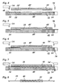
- the transverse grooves 16 ', 18' are kept shallower, so that they each receive only the lower half of the cross section of the transverse rods 16, 18, while the upper half of the cross section is received by corresponding grooves of the upper tool 44.
- the transverse grooves 16 ', 18' are on the left in FIGS. 2 and 3 limited by a stop 48 while they are open on the right side to the edge of the lower tool.
- the edge of the lower tool forms a shearing edge, on which the transverse rods 16, 18 can be sheared off.
- the transverse grooves 18 ' open into recesses 40' of the mold cavity 22 ', which correspond to the thickenings 40 of the support member 22.
- the longitudinal grooves 14 ' are locally expanded to templates 50, each of which a bending tool 52 is assigned.
- the longitudinal rods 14 are first inserted axially in the non-bent state in the longitudinal grooves 14 '.
- the longitudinal bars can be similar to the cross bars 16, 18 fed as a continuous material against a stop and then cut in the tool.
- the bending tools 52 are pulled outwardly, so that the bends 20 are formed in the longitudinal bars 14.
- the bending tools 52 which are associated with the same longitudinal groove 14 'are preferably actuated sequentially, so that the longitudinal bars 14 can move axially during the bending operation in the longitudinal grooves 14 to compensate for the bends 20 caused by the additional need for material.
- this can also be done with the aid of bending tools, which are integrated in the lower tool 42.
- FIG. 4 At the right edge of the injection mold is in FIG. 4 a cutting blade 56 is shown, which is also held vertically movable on the upper tool 44 and serves together with the cutting edge of the lower tool 42 to cut the cross bars 16, 18.
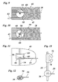
- FIGS. 9 to 11 A modified embodiment of the invention will be described below with reference to the FIGS. 9 to 11 explained.
- This embodiment differs from the previously described method in that the cross bars 16, 18 are not welded to the longitudinal bars, but are bent at the ends to eyes that tightly wrap the longitudinal bars. However, the bending of the eyelets is also about the same time with the injection molding.
- the upper tool 44 and the lower tool 42 respectively at the junction between the cross bar 18 and the longitudinal bar 14 recesses in the form of cylinder segments, which complement with a closed tool to a circular cylindrical cavity, which on the longitudinal bar 14 and associated longitudinal groove 14 'of the lower tool is centered.
Landscapes
- Engineering & Computer Science (AREA)
- Mechanical Engineering (AREA)
- Manufacturing & Machinery (AREA)
- Aviation & Aerospace Engineering (AREA)
- Transportation (AREA)
- Injection Moulding Of Plastics Or The Like (AREA)
- Moulds For Moulding Plastics Or The Like (AREA)
- Casting Or Compression Moulding Of Plastics Or The Like (AREA)
Claims (14)
- Procédé de fabrication d'un appui lombaire (12) comportant un élément de support (22) en matière plastique, dont la courbure peut être ajustée, sur des barreaux (18) d'une natte grillagée (10) formée de barreaux longitudinaux et de barreaux transversaux (14, 16, 18), caractérisé en ce que les barreaux (14, 16, 18) sont mis en place dans un outil de moulage par injection (42, 44) d'élément de support (22), les barreaux transversaux (18) sont en outre introduits dans des rainures transversales (18', 44) de l'outil de moulage par injection (42, 44) qui sont réalisées des deux côtés d'une cavité de moule (22') d'élément de support dans un outil inférieur (42) et un outil supérieur (44), et les barreaux transversaux (18) sont maintenus entre les outils inférieur et supérieur lors de la fermeture de l'outil de formage et sont noyés dans l'élément de support (22) lors du moulage par injection de celui-ci.
- Procédé selon la revendication 1, caractérisé en ce qu'au moins quelques-uns des barreaux (14, 16, 18) sont surmoulés avec la matière plastique de l'élément de support (22).
- Procédé selon la revendication 1 ou 2, caractérisé en ce que les barreaux transversaux (18), lorsqu'ils sont introduits dans les rainures transversales (18') de l'outil de moulage par injection (42, 44), sont poussés jusqu'à ce que leur extrémité soit contre une butée (48) réalisée dans l'outil de moulage par injection.
- Procédé selon la revendication 3, caractérisé en ce que les barreaux transversaux (18') sont amenés en continu et, lorsqu'ils sont immobilisés dans l'installation au niveau de la butée (48) de l'outil de moulage par injection (42, 44), sont coupés du côté de l'outil de moulage par injection opposé à la butée, une arête de l'outil de moulage par injection étant utilisée de préférence comme arête de coupe.
- Procédé selon l'une quelconque des revendications précédentes, caractérisé en ce que les barreaux transversaux (16, 18), mais aussi les barreaux longitudinaux (14) de la natte grillagée (10) sont mis en place dans l'outil de moulage par injection (42, 44) et sont reliés les uns avec les autres dans l'outil de moulage par injection.
- Procédé selon la revendication 5, caractérisé en ce que les barreaux longitudinaux (14) sont insérés en tant que barreaux droits, de préférence en continu, dans des rainures longitudinales (14') de l'outil de moulage par injection (42, 44).
- Procédé selon la revendication 6, caractérisé en ce que les barreaux longitudinaux (14) sont cintrés dans l'outil de moulage par injection (42, 44), une partie (42) de l'outil de moulage par injection servant de gabarit de cintrage (50).
- Procédé selon la revendication 6 ou 7, caractérisé en ce que des parties en matière plastique (70, 72) sont injectées au niveau des barreaux longitudinaux (14) de la natte grillagée.
- Procédé selon la revendication 8, caractérisé en ce qu'au moins quelques-unes de ces parties en matière plastique sont des gaines (70) pour les secteurs de liaison entre les barreaux longitudinaux (14) et les barreaux transversaux (16, 18).
- Procédé selon la revendication 8 ou 9, caractérisé en ce qu'au moins quelques-unes des parties en matière plastique sont des points d'ancrage (72) pour des ressorts de traction à accrocher au niveau des barreaux longitudinaux (14).
- Procédé selon l'une quelconque des revendications 8 à 10, caractérisé en ce que les parties en matière plastique (70, 72) sont injectées avec l'élément de support (22) en une opération.
- Procédé selon l'une quelconque des revendications 5 à 11, caractérisé en ce que les barreaux transversaux (16, 18) sont soudés avec les barreaux longitudinaux (14).
- Procédé selon l'une quelconque des revendications 5 à 11, caractérisé en ce que les barreaux transversaux (16, 18) sont fixés sur les barreaux longitudinaux (14) en cintrant les extrémités des barreaux transversaux (16, 18) autour des barreaux longitudinaux pour former des boucles (68) ou des crochets.
- Procédé de fabrication d'un élément de déclenchement pour des appuis-tête actifs d'un siège de véhicule, dans lequel un organe de service en matière plastique est fixé sur les barreaux (18) d'une natte grillagée (10) formée de barreaux longitudinaux et de barreaux transversaux (14, 16, 18), caractérisé en ce que les barreaux (14, 16, 18) sont mis en place dans un outil de moulage par injection (42, 44) d'organe de service, les barreaux transversaux (18) sont en outre introduits dans des rainures transversales (18', 44) de l'outil de moulage par injection (42, 44) qui sont réalisées des deux côtés d'une cavité de moule (22') d'organe de service dans un outil inférieur (42) et un outil supérieur (44), et les barreaux transversaux (18) sont maintenus entre les outils inférieur et supérieur lors de la fermeture de l'outil de formage et sont noyés dans l'organe de service lors de l'injection de celui-ci.
Applications Claiming Priority (2)
| Application Number | Priority Date | Filing Date | Title |
|---|---|---|---|
| DE10110138 | 2001-03-02 | ||
| DE10110138A DE10110138A1 (de) | 2001-03-02 | 2001-03-02 | Verfahren zur Herstellung einer Lordosenstütze |
Publications (3)
| Publication Number | Publication Date |
|---|---|
| EP1236610A2 EP1236610A2 (fr) | 2002-09-04 |
| EP1236610A3 EP1236610A3 (fr) | 2004-01-28 |
| EP1236610B1 true EP1236610B1 (fr) | 2008-04-30 |
Family
ID=7676108
Family Applications (1)
| Application Number | Title | Priority Date | Filing Date |
|---|---|---|---|
| EP02004411A Expired - Lifetime EP1236610B1 (fr) | 2001-03-02 | 2002-02-26 | Procédé de fabrication d'un appui lombaire |
Country Status (3)
| Country | Link |
|---|---|
| US (1) | US7120984B2 (fr) |
| EP (1) | EP1236610B1 (fr) |
| DE (2) | DE10110138A1 (fr) |
Families Citing this family (15)
| Publication number | Priority date | Publication date | Assignee | Title |
|---|---|---|---|---|
| DE10220028B4 (de) | 2002-05-04 | 2011-07-28 | Schwarzbich, Jörg, 33607 | Sitzeinlage und Verfahren zu ihrer Herstellung |
| WO2006081865A1 (fr) * | 2005-02-02 | 2006-08-10 | Schukra Gerätebau AG | Element de soutien dorsolombaire et son procede de production |
| US7585027B2 (en) * | 2006-04-07 | 2009-09-08 | Schukra Of North America | Overmolded thin-profile lumbar support |
| KR100901568B1 (ko) * | 2006-12-12 | 2009-06-08 | 현대자동차주식회사 | 연료전지용 금속분리판의 제조방법 |
| EP1955836A1 (fr) * | 2007-02-09 | 2008-08-13 | L&P Swiss Holding Company | Procédé et appareil pour la fabrication d'un tampon de suspension et tampon de suspension correspondant |
| DE102007034187B4 (de) * | 2007-07-23 | 2013-10-31 | Fico Cables Lda | Stützmatte für einen Kraftfahrzeugsitz |
| JP5621520B2 (ja) * | 2010-11-05 | 2014-11-12 | トヨタ紡織株式会社 | 乗物用シート |
| US8684460B2 (en) | 2011-06-15 | 2014-04-01 | Brose Fahrzeugteile Gmbh & Co. Kg, Coburg | Backrest structure for a seat with lumbar support and curving element comprising a pre-tensioning connecting element |
| EP2939569B1 (fr) * | 2014-05-02 | 2018-03-28 | Schukra Gerätebau GmbH | Procédé de production d'un dispositif de support lombaire, dispositif de support lombaire et siège de véhicule |
| KR101683976B1 (ko) | 2014-08-12 | 2016-12-07 | 현대자동차주식회사 | 차량용 시트백 서스펜션 어셈블리 및 이의 제조방법 |
| US11166450B2 (en) | 2016-11-02 | 2021-11-09 | Bird B Gone Llc | Devices and methods for repelling avian pests |
| US10926683B2 (en) * | 2018-04-12 | 2021-02-23 | Ts Tech Co., Ltd. | Conveyance seat |
| DE102018127626A1 (de) * | 2018-11-06 | 2020-05-07 | Faurecia Autositze Gmbh | Polsterlager für einen Fahrzeugsitz |
| US12599240B2 (en) * | 2021-07-05 | 2026-04-14 | Secretlab Sg Pte. Ltd. | Lumbar support assembly and related method, and a backrest assembly |
| KR102726198B1 (ko) * | 2021-07-23 | 2024-11-06 | 주식회사 디에스시동탄 | 럼버 서포트 어셈블리 |
Family Cites Families (39)
| Publication number | Priority date | Publication date | Assignee | Title |
|---|---|---|---|---|
| US2596993A (en) * | 1949-01-13 | 1952-05-20 | United Shoe Machinery Corp | Method and mold for covering of eyelets by plastic injection |
| BE539367A (fr) * | 1954-06-29 | 1955-07-15 | ||
| DE1479974A1 (de) * | 1962-03-31 | 1969-07-17 | Basf Ag | Verfahren zur Herstellung von stossfesten Kunststoffschaumplatten |
| US3458931A (en) * | 1963-09-16 | 1969-08-05 | Western Electric Co | Method for molding terminals in workpieces |
| US3264034A (en) * | 1964-03-25 | 1966-08-02 | David E Lawson | Load bearing structure |
| GB1140261A (en) * | 1964-04-29 | 1969-01-15 | Elisa Berthelsen | Improvements in and relating to structural frames such as window frames |
| US3389461A (en) * | 1965-04-08 | 1968-06-25 | Ibm | Molded insulator base having embedded terminals and method of forming the same |
| US3391426A (en) * | 1965-10-22 | 1968-07-09 | Motorola Inc | Molding apparatus |
| GB1390379A (en) * | 1972-06-28 | 1975-04-09 | Serck Industries Ltd | Method of manufacturing hollow articles eg heat exchangers |
| US3860287A (en) * | 1972-08-28 | 1975-01-14 | Flex O Lators | Seating construction |
| US3991146A (en) * | 1974-04-01 | 1976-11-09 | Imperial Chemical Industries Limited | Method of encapsulating an insert in plastics material by injection molding |
| AT373199B (de) * | 1979-12-13 | 1983-12-27 | Schmied K G Silhouette Modellb | Verfahren zum herstellen von werkstuecken, insbesondere von brillenbuegeln |
| FR2532883B2 (fr) * | 1982-09-14 | 1988-06-24 | Duret M & Fils | Procede pour la realisation d'un element de siege par le moulage d'un cadre sur une garniture et element de siege obtenu par ledit procede |
| FR2534792B1 (fr) * | 1982-10-25 | 1985-10-18 | Citroen Sa | Siege a suspension integree et procede de fabrication de l'armature de ce siege |
| US4722821A (en) * | 1983-12-30 | 1988-02-02 | The Boeing Company | Method of making a cascade basket for a thrust reverser |
| FR2572987B1 (fr) * | 1984-09-21 | 1987-01-02 | Pont A Mousson | Procede et dispositif de surmoulage d'un entourage de dimensions precises sur le pourtour d'une piece plane ou galbee a tolerances dimensionnelles |
| JPS6292817A (ja) | 1985-10-18 | 1987-04-28 | Meihou Kinzoku Kogyosho:Kk | 複数のインサ−トを有する樹脂成形品の成形方法 |
| DE3612576C1 (de) * | 1986-04-15 | 1987-06-19 | Preh Elektro Feinmechanik | Elektrisches Bauteil mit Kunststoffmantel und Verfahren zu dessen Herstellung |
| JPS6378717A (ja) * | 1986-09-22 | 1988-04-08 | Fuji Xerox Co Ltd | 金属板と合成樹脂の複合部材製造方法 |
| JPH0780198B2 (ja) * | 1987-08-27 | 1995-08-30 | 富士ゼロックス株式会社 | 射出成形による複合部材の製造方法 |
| JP2686761B2 (ja) * | 1988-02-22 | 1997-12-08 | 株式会社山城精機製作所 | インサート物ベンド機構を有する金型装置 |
| US5190803A (en) * | 1988-11-25 | 1993-03-02 | Bayer Aktiengesellschaft | Structural shell with reinforcing ribs connected via perforations |
| DE4023967C1 (fr) * | 1990-07-27 | 1991-10-02 | Weisser Spulenkoerper Gmbh & Co Kg, 7086 Neresheim, De | |
| FR2666771B1 (fr) * | 1990-09-19 | 1992-12-18 | Europ Sieges Automobiles | Appui-tete notamment pour siege de vehicule. |
| US5564809A (en) * | 1991-03-07 | 1996-10-15 | Donnelly Technology, Inc. | Encapsulated shelf for refrigerated compartments |
| DE4405495C2 (de) * | 1994-02-21 | 1996-05-09 | Schuster Wilhelm | Rückenlehne für Sitze mit einer Schale und einer verstellbaren Lordosenstütze |
| US5609652A (en) * | 1994-04-13 | 1997-03-11 | Koito Manufacturing Co., Ltd. | Method of manufacturing a synthetic resin part integrally formed with metal members |
| FR2726334B1 (fr) * | 1994-10-28 | 1997-01-17 | Cesa | Attache et son application a la jonction de fils d'une nappe support de coussin de siege |
| DE4444803C2 (de) * | 1994-12-15 | 1997-04-24 | Ameu Management Corp | Elastisches Wölbelement aus Kunststoff mit Längs- und Querstreben für eine wölbungsverstellbare Lordosenstütze |
| DE29504287U1 (de) * | 1995-03-13 | 1995-05-11 | Bonke, Christoph, Dr., 83126 Flintsbach | Individuell anpaßbare Kopfstütze für Sitze mit Rückenlehne |
| EP0780262B1 (fr) | 1995-12-23 | 1999-06-30 | Jörg Schwarzbich | Dispositif pour la fixation d'un élément de support à un grillage en fils |
| US5971618A (en) * | 1996-05-26 | 1999-10-26 | Valu Engineering, Inc. | Flange bearing having reinforced molded housing |
| IT1284666B1 (it) * | 1996-07-16 | 1998-05-21 | Bruzolo Manifatt Gestind Mb | Appoggiatesta per sedili di autoveicoli. |
| US5799548A (en) * | 1996-07-22 | 1998-09-01 | Lexmark International, Inc. | Frame with molded features |
| FR2759649B1 (fr) * | 1997-02-17 | 1999-04-23 | Faure Bertrand Equipements Sa | Nappe de support de matelassure d'un siege de vehicule automobile |
| AT408064B (de) * | 1999-08-04 | 2001-08-27 | Schukra Berndorf Ges M B H | Anatomisch formbare stütze |
| DE19943890C1 (de) * | 1999-09-14 | 2001-02-15 | Faure Bertrand Sitztech Gmbh | Sitzteil eines Kraftfahrzeugsitzes |
| US6758522B2 (en) * | 2001-03-29 | 2004-07-06 | L&P Property Management Company | Apparatus and method for varying coefficients of friction in a variable apex back support |
| DE10220028B4 (de) * | 2002-05-04 | 2011-07-28 | Schwarzbich, Jörg, 33607 | Sitzeinlage und Verfahren zu ihrer Herstellung |
-
2001
- 2001-03-02 DE DE10110138A patent/DE10110138A1/de not_active Withdrawn
-
2002
- 2002-02-26 DE DE50212172T patent/DE50212172D1/de not_active Expired - Lifetime
- 2002-02-26 EP EP02004411A patent/EP1236610B1/fr not_active Expired - Lifetime
- 2002-03-01 US US10/087,456 patent/US7120984B2/en not_active Expired - Fee Related
Also Published As
| Publication number | Publication date |
|---|---|
| DE10110138A1 (de) | 2002-09-05 |
| US7120984B2 (en) | 2006-10-17 |
| EP1236610A2 (fr) | 2002-09-04 |
| US20020140124A1 (en) | 2002-10-03 |
| DE50212172D1 (de) | 2008-06-12 |
| EP1236610A3 (fr) | 2004-01-28 |
Similar Documents
| Publication | Publication Date | Title |
|---|---|---|
| EP1236610B1 (fr) | Procédé de fabrication d'un appui lombaire | |
| DE19515585C2 (de) | Spitzgießform zur Herstellung eines Lenkradpolsters und Verfahren zur Herstellung des Lenkradpolsters | |
| EP1501389B1 (fr) | Garniture de siege et son procede de production | |
| DE60310061T2 (de) | Rasiersystem | |
| EP2225080B1 (fr) | Procédé de production d'éléments composites | |
| EP0780262A1 (fr) | Dispositif pour la fixation d'un élément de support à un grillage en fils | |
| DE102008051072A1 (de) | Kraftfahrzeugsitz mit Lendenstütze für ein Anti-Schleudertraumasystem | |
| DE102008038851A1 (de) | Lehnenrahmen eines Fahrzeugsitzes | |
| DE29822649U1 (de) | Schaumteil aus Polyurethan o.dgl., insbesondere zur Verwendung als Polsterelement bei der Herstellung von Fahrzeugsitzen | |
| DE3521897A1 (de) | Aeussere schneidvorrichtung fuer einen elektrorasierer | |
| WO2011095302A1 (fr) | Dossier en matière plastique comprenant des éléments fonctionnels formés en matière plastique ou revêtus de matière plastique | |
| WO2003097431A1 (fr) | Composant leger pour elements de support de vehicules automobiles | |
| EP1747977A1 (fr) | Procédé de production d'un composant moussé et moule de moussage pour appliquer ce procédé | |
| EP3231572A1 (fr) | Outil et procédé de fabrication d'un corps en mousse et corps en mousse | |
| DE102010036798B4 (de) | Sitzteil | |
| DE102007052960A1 (de) | Modulare Sitzaufbaustruktur | |
| DE102007015466A1 (de) | Verfahren zur Herstellung einer Dichtungsanordnung, insbesondere für ein Kraftfahrzeug, mit einem Dichtungselement und einem Träger sowie eine solche Dichtungsanordnung | |
| EP2585339B1 (fr) | Dossier de siège de véhicule à moteur | |
| WO2016071403A1 (fr) | Dispositif formant carter de siège ayant une matière composite et procede de production de celui-ci | |
| EP1682799B1 (fr) | Pommeau de levier de vitesses pour vehicule | |
| EP1065084B1 (fr) | Patin à glissement pour une partie mobile de véhicule, en particulier pour toit coulissant | |
| EP3305497A1 (fr) | Moule et procédé pour la fabrication un article composite surmoulé | |
| AT395805B (de) | Band- oder riemenfoermiger bauteil, insbesondere uhrarmband | |
| DE9419722U1 (de) | Belüftungsauslaß, insbesondere für Kraftfahrzeuge | |
| DE102009007721A1 (de) | System zum Befestigen eines Anbauteils an einem Trägerbauteil und Verfahren zum Herstellen des Trägerbauteils |
Legal Events
| Date | Code | Title | Description |
|---|---|---|---|
| PUAI | Public reference made under article 153(3) epc to a published international application that has entered the european phase |
Free format text: ORIGINAL CODE: 0009012 |
|
| AK | Designated contracting states |
Kind code of ref document: A2 Designated state(s): AT BE CH CY DE DK ES FI FR GB GR IE IT LI LU MC NL PT SE TR |
|
| AX | Request for extension of the european patent |
Free format text: AL;LT;LV;MK;RO;SI |
|
| PUAL | Search report despatched |
Free format text: ORIGINAL CODE: 0009013 |
|
| AK | Designated contracting states |
Kind code of ref document: A3 Designated state(s): AT BE CH CY DE DK ES FI FR GB GR IE IT LI LU MC NL PT SE TR |
|
| AX | Request for extension of the european patent |
Extension state: AL LT LV MK RO SI |
|
| 17P | Request for examination filed |
Effective date: 20040218 |
|
| AKX | Designation fees paid |
Designated state(s): DE ES FR GB IT SE |
|
| 17Q | First examination report despatched |
Effective date: 20061229 |
|
| GRAP | Despatch of communication of intention to grant a patent |
Free format text: ORIGINAL CODE: EPIDOSNIGR1 |
|
| GRAS | Grant fee paid |
Free format text: ORIGINAL CODE: EPIDOSNIGR3 |
|
| GRAA | (expected) grant |
Free format text: ORIGINAL CODE: 0009210 |
|
| AK | Designated contracting states |
Kind code of ref document: B1 Designated state(s): DE ES FR GB IT SE |
|
| REG | Reference to a national code |
Ref country code: GB Ref legal event code: FG4D Free format text: NOT ENGLISH |
|
| REF | Corresponds to: |
Ref document number: 50212172 Country of ref document: DE Date of ref document: 20080612 Kind code of ref document: P |
|
| PG25 | Lapsed in a contracting state [announced via postgrant information from national office to epo] |
Ref country code: ES Free format text: LAPSE BECAUSE OF FAILURE TO SUBMIT A TRANSLATION OF THE DESCRIPTION OR TO PAY THE FEE WITHIN THE PRESCRIBED TIME-LIMIT Effective date: 20080810 |
|
| PG25 | Lapsed in a contracting state [announced via postgrant information from national office to epo] |
Ref country code: SE Free format text: LAPSE BECAUSE OF FAILURE TO SUBMIT A TRANSLATION OF THE DESCRIPTION OR TO PAY THE FEE WITHIN THE PRESCRIBED TIME-LIMIT Effective date: 20080731 |
|
| ET | Fr: translation filed | ||
| PLBE | No opposition filed within time limit |
Free format text: ORIGINAL CODE: 0009261 |
|
| STAA | Information on the status of an ep patent application or granted ep patent |
Free format text: STATUS: NO OPPOSITION FILED WITHIN TIME LIMIT |
|
| 26N | No opposition filed |
Effective date: 20090202 |
|
| PG25 | Lapsed in a contracting state [announced via postgrant information from national office to epo] |
Ref country code: IT Free format text: LAPSE BECAUSE OF FAILURE TO SUBMIT A TRANSLATION OF THE DESCRIPTION OR TO PAY THE FEE WITHIN THE PRESCRIBED TIME-LIMIT Effective date: 20080430 |
|
| PGFP | Annual fee paid to national office [announced via postgrant information from national office to epo] |
Ref country code: FR Payment date: 20120214 Year of fee payment: 11 |
|
| PGFP | Annual fee paid to national office [announced via postgrant information from national office to epo] |
Ref country code: DE Payment date: 20120229 Year of fee payment: 11 |
|
| PGFP | Annual fee paid to national office [announced via postgrant information from national office to epo] |
Ref country code: GB Payment date: 20120203 Year of fee payment: 11 |
|
| GBPC | Gb: european patent ceased through non-payment of renewal fee |
Effective date: 20130226 |
|
| REG | Reference to a national code |
Ref country code: FR Ref legal event code: ST Effective date: 20131031 |
|
| REG | Reference to a national code |
Ref country code: DE Ref legal event code: R119 Ref document number: 50212172 Country of ref document: DE Effective date: 20130903 |
|
| PG25 | Lapsed in a contracting state [announced via postgrant information from national office to epo] |
Ref country code: FR Free format text: LAPSE BECAUSE OF NON-PAYMENT OF DUE FEES Effective date: 20130228 Ref country code: DE Free format text: LAPSE BECAUSE OF NON-PAYMENT OF DUE FEES Effective date: 20130903 Ref country code: GB Free format text: LAPSE BECAUSE OF NON-PAYMENT OF DUE FEES Effective date: 20130226 |