EP1236896A2 - Piston de compresseur - Google Patents
Piston de compresseur Download PDFInfo
- Publication number
- EP1236896A2 EP1236896A2 EP02004509A EP02004509A EP1236896A2 EP 1236896 A2 EP1236896 A2 EP 1236896A2 EP 02004509 A EP02004509 A EP 02004509A EP 02004509 A EP02004509 A EP 02004509A EP 1236896 A2 EP1236896 A2 EP 1236896A2
- Authority
- EP
- European Patent Office
- Prior art keywords
- piston
- groove
- sealing coat
- type compressor
- cylinder block
- Prior art date
- Legal status (The legal status is an assumption and is not a legal conclusion. Google has not performed a legal analysis and makes no representation as to the accuracy of the status listed.)
- Granted
Links
Images


Classifications
-
- F—MECHANICAL ENGINEERING; LIGHTING; HEATING; WEAPONS; BLASTING
- F04—POSITIVE - DISPLACEMENT MACHINES FOR LIQUIDS; PUMPS FOR LIQUIDS OR ELASTIC FLUIDS
- F04B—POSITIVE-DISPLACEMENT MACHINES FOR LIQUIDS; PUMPS
- F04B27/00—Multi-cylinder pumps specially adapted for elastic fluids and characterised by number or arrangement of cylinders
- F04B27/08—Multi-cylinder pumps specially adapted for elastic fluids and characterised by number or arrangement of cylinders having cylinders coaxial with, or parallel or inclined to, main shaft axis
- F04B27/0873—Component parts, e.g. sealings; Manufacturing or assembly thereof
- F04B27/0878—Pistons
-
- F—MECHANICAL ENGINEERING; LIGHTING; HEATING; WEAPONS; BLASTING
- F05—INDEXING SCHEMES RELATING TO ENGINES OR PUMPS IN VARIOUS SUBCLASSES OF CLASSES F01-F04
- F05C—INDEXING SCHEME RELATING TO MATERIALS, MATERIAL PROPERTIES OR MATERIAL CHARACTERISTICS FOR MACHINES, ENGINES OR PUMPS OTHER THAN NON-POSITIVE-DISPLACEMENT MACHINES OR ENGINES
- F05C2201/00—Metals
- F05C2201/02—Light metals
- F05C2201/021—Aluminium
-
- F—MECHANICAL ENGINEERING; LIGHTING; HEATING; WEAPONS; BLASTING
- F05—INDEXING SCHEMES RELATING TO ENGINES OR PUMPS IN VARIOUS SUBCLASSES OF CLASSES F01-F04
- F05C—INDEXING SCHEME RELATING TO MATERIALS, MATERIAL PROPERTIES OR MATERIAL CHARACTERISTICS FOR MACHINES, ENGINES OR PUMPS OTHER THAN NON-POSITIVE-DISPLACEMENT MACHINES OR ENGINES
- F05C2201/00—Metals
- F05C2201/04—Heavy metals
- F05C2201/0469—Other heavy metals
- F05C2201/049—Lead
-
- F—MECHANICAL ENGINEERING; LIGHTING; HEATING; WEAPONS; BLASTING
- F05—INDEXING SCHEMES RELATING TO ENGINES OR PUMPS IN VARIOUS SUBCLASSES OF CLASSES F01-F04
- F05C—INDEXING SCHEME RELATING TO MATERIALS, MATERIAL PROPERTIES OR MATERIAL CHARACTERISTICS FOR MACHINES, ENGINES OR PUMPS OTHER THAN NON-POSITIVE-DISPLACEMENT MACHINES OR ENGINES
- F05C2201/00—Metals
- F05C2201/04—Heavy metals
- F05C2201/0469—Other heavy metals
- F05C2201/0493—Tin
-
- F—MECHANICAL ENGINEERING; LIGHTING; HEATING; WEAPONS; BLASTING
- F05—INDEXING SCHEMES RELATING TO ENGINES OR PUMPS IN VARIOUS SUBCLASSES OF CLASSES F01-F04
- F05C—INDEXING SCHEME RELATING TO MATERIALS, MATERIAL PROPERTIES OR MATERIAL CHARACTERISTICS FOR MACHINES, ENGINES OR PUMPS OTHER THAN NON-POSITIVE-DISPLACEMENT MACHINES OR ENGINES
- F05C2201/00—Metals
- F05C2201/04—Heavy metals
- F05C2201/0469—Other heavy metals
- F05C2201/0496—Zinc
-
- F—MECHANICAL ENGINEERING; LIGHTING; HEATING; WEAPONS; BLASTING
- F05—INDEXING SCHEMES RELATING TO ENGINES OR PUMPS IN VARIOUS SUBCLASSES OF CLASSES F01-F04
- F05C—INDEXING SCHEME RELATING TO MATERIALS, MATERIAL PROPERTIES OR MATERIAL CHARACTERISTICS FOR MACHINES, ENGINES OR PUMPS OTHER THAN NON-POSITIVE-DISPLACEMENT MACHINES OR ENGINES
- F05C2225/00—Synthetic polymers, e.g. plastics; Rubber
- F05C2225/04—PTFE [PolyTetraFluorEthylene]
-
- F—MECHANICAL ENGINEERING; LIGHTING; HEATING; WEAPONS; BLASTING
- F05—INDEXING SCHEMES RELATING TO ENGINES OR PUMPS IN VARIOUS SUBCLASSES OF CLASSES F01-F04
- F05C—INDEXING SCHEME RELATING TO MATERIALS, MATERIAL PROPERTIES OR MATERIAL CHARACTERISTICS FOR MACHINES, ENGINES OR PUMPS OTHER THAN NON-POSITIVE-DISPLACEMENT MACHINES OR ENGINES
- F05C2253/00—Other material characteristics; Treatment of material
- F05C2253/12—Coating
Definitions
- the present invention relates to a compressor. More particularly, the present invention relates to a piston type compressor that provides a piston ring fitted onto a piston.
- a piston type compressor such as a swash plate type compressor generally includes a cylinder block and suction and discharge chambers so as to sandwich a valve plate assembly, and the cylinder block accommodates a piston.
- a piston By reciprocation of the pistons, fluid in the suction chamber is sucked into the cylinder block, and the fluid sucked in the cylinder block is compressed and discharged to the discharge chamber.
- sealing performance between the pistons and the cylinder block is important.
- Japanese Unexamined Patent Publication No. 11-294322 discloses a compressor that provides a coating made of fluoro resin on the outer circumferential surface of the pistons and a piston ring fitted onto the pistons. Thereby, sealing performance between the pistons and the cylinder block is ensured.
- sealing performance between the pistons and the piston rings in addition to sealing performance of the pistons and the cylinder block is also required to improve.
- Alternative refrigerant gas such as carbon dioxide is promoted to be a practical use to deal with environmental problems these days.
- carbon dioxide for using in a compressor as a compressing target requires quite a high compression ratio. Therefore, the above-mentioned requirements for sealing performance have been further increasing these days.
- the present invention addresses the above-mentioned problems traceable to a relatively high compression ratio by improving sealing performance between pistons and piston rings.
- a piston type compressor has a housing, a cylinder block and a piston.
- the cylinder block is fixed to the housing.
- the piston is accommodated in the cylinder block.
- a piston ring is provided between the cylinder block and the piston.
- a sealing coat is made of soft metal, and is provided between the piston ring and the piston.
- sealing performance between the piston ring and the piston is improved by the sealing coat made of soft metal.
- the present invention also provides a method of forming a sealing coat on a surface of a groove on a piston.
- the method includes forming a coat made of fluoro resin on the outer circumferential surface of the piston, recessing a groove for accommodating a piston ring on the outer circumferential surface of the piston by machining, and immersing the piston in soft metal.
- FIG. 1 An embodiment of the present invention, which is applied to a swash plate type variable displacement piston type compressor for compressing refrigerant gas, will now be described with reference to Figs. 1 through 4.
- the left side and the right side in Fig. 1 correspond to the front end and the rear end, respectively.
- a bolt 4 screws a front housing 1 to a rear housing 2 via a gasket 3, thus constructing a housing 5 of a compressor.
- the rear housing 2 provides a step 6 inside.
- a retainer plate 7, a discharge valve plate 8, a valve plate 9 and a suction valve plate 10 are fitted onto the step 6.
- the retainer plate 7 and a rear end wall 11 of the rear housing 2 define a suction chamber 12 and a discharge chamber 13 such that a partition wall 14 separates the suction chamber 12 and the discharge chamber 13 from each other.
- a cylinder block 15 is fitted onto the suction valve plate 10 in the rear housing 2.
- the cylinder block 15 and the front housing 1 rotatably support a drive shaft 16.
- the drive shaft 16 protrudes its front end outside the front housing 1, and connects with a driving source such as an engine and a motor of a vehicle, which is not shown.
- a lug plate 17 is secured to the drive shaft 16, and a swash plate 18 engages with the lug plate 17.
- the drive shaft 16 extends a through hole, which is formed through the center of the swash plate 18.
- a pair of guide pins 19 extending from the swash plate 18 is slidably fitted into a pair of guide holes 20 formed with the lug plate 17.
- the swash plate 18 integrally rotates with the drive shaft 16 so that the guide pins 19 engages with the guide holes 20, and is tiltably supported by the drive shaft 16 so as to slide along the axis of the drive shaft 16.
- a plurality of cylinder bores 21 is defined in the cylinder block 15 so as to surround the drive shaft 16, the cylinder bores 21 each slidably accommodate respective pistons 22.
- the pistons 22 each engage with the periphery of the swash plate 18 through a pair of shoes 23. As the swash plate 18 rotates with the drive shaft 16, the pistons 22 each reciprocate relative to the axis of the drive shaft 16 in the associated cylinder bores 21 through shoes 23.
- the single cylinder bore 21 and the single piston 22 are shown in Fig. 1. However, the compressor provides seven cylinder bores 21 and the seven pistons 22 in this embodiment.
- the discharge chamber 13 communicates with a crank chamber 29, or a control chamber 29, which is defined in the front housing 1 via a supply passage 27 and a control valve 28, and the crank chamber 29 communicates with the suction chamber 12 via a bleed passage 30.
- the control valve 28 opens, refrigerant gas in the discharge chamber 13 flows into the crank chamber 29 via the supply passage 27 and the control valve 28, thus increasing pressure in the crank chamber 29.
- the inclination of the swash plate 18 varies in accordance with the pressure in the crank chamber 29. As the pressure in the crank chamber 29 increases, the inclination angle relative to the plane perpendicular to the axis of the drive shaft 16 decreases. As the pressure in the crank chamber 29 decreases, the inclination angle increases. Namely, the inclination of the swash plate 18 is varied by adjusting the control valve 28 due to an external control or an internal control.
- the outer circumferential surface of the pistons 22 adjacent to a piston head each provide annular grooves 31.
- a groove surface 22a, the cross section of which is rectangular defines the groove 31 on the piston 22.
- An annular piston ring 32 occupies the groove 31.
- the piston ring 32 is made by shaping a cast iron member, the cross section of which is rectangular, into a ring.
- the groove surface 22a provides soft metal, or a sealing coat 33 made of tin in the present embodiment by nonelectrolytically coating. The thickness of the tin sealing coat 33 is from 2 ⁇ m to 3 ⁇ m. A process of forming the sealing coat 33 will now be described.
- a coat made of fluoro resin is formed on the outer circumferential surface of the piston22, which is made of aluminum.
- the groove 31 is recessed by machining.
- the tin sealing coat 33 coats the groove surface 22a by immersing the piston 22 with the groove 31 in tin. No tin coats the circumferential surface of the piston 22, which is coated with fluoro resin. Since the groove 31 is formed by machining, the tin sealing coat 33 coats the groove surface 22a, which is not coated with fluoro resin.
- the following processes are required: 1) recessing a groove on a piston; 2) coating with resin; and 3) treating the surface of a resin coat.
- the above-described process 1) recessing a groove on a piston and process 2) coating with tin are required only. Thereby, manufacturing cost is reduced. Also, wettability of the tin sealing coat is higher than that of the resin sealing coat. Therefore, the tin sealing coat is available in performing such higher sealing performance relative to the resin sealing coat without treating the surface of the tin sealing coat.
- the tin sealing coat 33 raises sealing performance between the piston ring 32 and the piston 22 during reciprocation of the piston 22, and inhibits the refrigerant gas from leaking therebetween. Therefore, compression efficiency improves, and lubrication is ensured. Also, when roughness of the groove surface 22a does not satisfies requirement, high sealing performance is ensured by coating the groove surface 22a with the tin sealing coat 33.
- the sealing coat is not limited to the tin sealing coat.
- other soft metals which performs high wettability with lubricant such as lead and zinc may be applied.
- a position coated with the sealing coat, which is made of soft metal is not limited to the groove surface 22a.
- the sealing coat may coat the piston ring 32.
- the groove 31 on the piston is not limited to a single groove. As shown in Fig. 4, a plurality of the grooves 31 may be recessed on the piston 22.
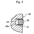
- the sealing coat may coat parts of the groove surface 22a, as shown in Fig. 5. Particularly, the sealing coat resides only on the facing end surfaces of the groove surface 22a other than the bottom of the groove surface 22a.
- the piston type compressor provides the sealing coat, which is made of soft metal, between the piston ring and the piston. Thereby, sealing performance therebetween improves, and compression efficiency improves.
- a sealing coat which is made of soft metal, is a film coating the surface of a groove on a piston, and even when roughness of the surface of the groove does not satisfies requirement, high sealing performance is ensured.
- a piston type compressor has a housing, a cylinder block and a piston.
- the cylinder block is fixed to the housing.
- the piston is accommodated in the cylinder block.
- a piston ring is provided between the cylinder block and the piston.
- a sealing coat is made of soft metal, and is provided between the piston ring and the piston.
Landscapes
- Engineering & Computer Science (AREA)
- Manufacturing & Machinery (AREA)
- Mechanical Engineering (AREA)
- General Engineering & Computer Science (AREA)
- Compressor (AREA)
- Compressors, Vaccum Pumps And Other Relevant Systems (AREA)
Applications Claiming Priority (2)
| Application Number | Priority Date | Filing Date | Title |
|---|---|---|---|
| JP2001058214 | 2001-03-02 | ||
| JP2001058214A JP2002257045A (ja) | 2001-03-02 | 2001-03-02 | ピストン型圧縮機 |
Publications (3)
| Publication Number | Publication Date |
|---|---|
| EP1236896A2 true EP1236896A2 (fr) | 2002-09-04 |
| EP1236896A3 EP1236896A3 (fr) | 2003-07-16 |
| EP1236896B1 EP1236896B1 (fr) | 2006-07-26 |
Family
ID=18917973
Family Applications (1)
| Application Number | Title | Priority Date | Filing Date |
|---|---|---|---|
| EP02004509A Expired - Lifetime EP1236896B1 (fr) | 2001-03-02 | 2002-02-27 | Piston de compresseur |
Country Status (4)
| Country | Link |
|---|---|
| US (1) | US6705207B2 (fr) |
| EP (1) | EP1236896B1 (fr) |
| JP (1) | JP2002257045A (fr) |
| DE (1) | DE60213298D1 (fr) |
Cited By (2)
| Publication number | Priority date | Publication date | Assignee | Title |
|---|---|---|---|---|
| US7730939B2 (en) | 2008-03-27 | 2010-06-08 | Oil Flow Usa, Inc. | Safety clamp for walking beam compressor |
| US8047820B2 (en) | 2008-03-27 | 2011-11-01 | Oil Flow Usa, Inc. | Stuffing box for walking beam compressor |
Families Citing this family (6)
| Publication number | Priority date | Publication date | Assignee | Title |
|---|---|---|---|---|
| JP2002266759A (ja) * | 2001-03-12 | 2002-09-18 | Toyota Industries Corp | 圧縮機 |
| US7240655B2 (en) * | 2004-05-26 | 2007-07-10 | Sri International | Compliant walled combustion devices II |
| US7237524B2 (en) * | 2004-05-26 | 2007-07-03 | Sri International | Compliant walled combustion devices |
| US7281465B2 (en) * | 2006-01-09 | 2007-10-16 | Delphi Technologies, Inc. | Compressor piston ball pocket coating |
| US20090246049A1 (en) * | 2008-03-27 | 2009-10-01 | Oil Flow Usa, Inc. | Coated cylinder for walking beam compressor |
| EP2865893B1 (fr) * | 2013-09-23 | 2021-04-28 | Halla Visteon Climate Control Corp. | Ensemble de soupape pour compresseur à plateau oscillant variable |
Family Cites Families (17)
| Publication number | Priority date | Publication date | Assignee | Title |
|---|---|---|---|---|
| US2575214A (en) * | 1948-09-30 | 1951-11-13 | Wright Aeronautical Corp | Piston with plated piston ring grooves |
| US3914574A (en) * | 1973-10-01 | 1975-10-21 | Wellworthy Ltd | Fabricated piston with sprayed groove |
| JPS5352264A (en) * | 1976-10-25 | 1978-05-12 | Hitachi Ltd | Soldering method |
| BE870460A (fr) * | 1978-09-13 | 1979-03-13 | Danese Desire | Procede de traitement de metallisation et produits obtenus |
| JPS5976868A (ja) * | 1982-10-26 | 1984-05-02 | Showa Denko Kk | 溶射用マスク |
| JPH0341102A (ja) | 1989-07-07 | 1991-02-21 | Kanebo Ltd | アクリロニトリル系の溶液重合に於る着色防止法 |
| US5241748A (en) * | 1991-06-27 | 1993-09-07 | Teikoku Piston Ring Co., Ltd. | Method for manufacturing a compression ring |
| US5392692A (en) * | 1994-03-14 | 1995-02-28 | Ford Motor Company | Antiblow-by piston and seal construction for high temperature applications |
| JPH08109882A (ja) | 1994-10-13 | 1996-04-30 | Sanyo Electric Co Ltd | ピストン及びコンプレッサ |
| WO1997042411A1 (fr) * | 1996-05-08 | 1997-11-13 | Kabushiki Kaisha Toyoda Jidoshokki Seisakusho | Compresseur a deplacement alternatif |
| CH689566A5 (de) * | 1995-03-10 | 1999-06-15 | Daimler Benz Ag | Kolben mit Kolbenstange. |
| JPH08246947A (ja) * | 1995-03-13 | 1996-09-24 | Nissan Motor Co Ltd | ピストンの製造方法 |
| US5713324A (en) * | 1996-04-19 | 1998-02-03 | Dana Corporation | Piston ring coating |
| JPH10169557A (ja) * | 1996-12-06 | 1998-06-23 | Toyota Autom Loom Works Ltd | 圧縮機 |
| IT1289769B1 (it) * | 1996-12-19 | 1998-10-16 | Nuova Dari S P A | Compressore alternativo |
| JPH11294322A (ja) * | 1998-04-17 | 1999-10-26 | Toyota Autom Loom Works Ltd | 斜板式圧縮機 |
| DE19833827C1 (de) * | 1998-07-28 | 1999-12-16 | Man B & W Diesel Ag | Kolben für eine Hubkolbenbrennkraftmaschine |
-
2001
- 2001-03-02 JP JP2001058214A patent/JP2002257045A/ja active Pending
-
2002
- 2002-02-27 EP EP02004509A patent/EP1236896B1/fr not_active Expired - Lifetime
- 2002-02-27 DE DE60213298T patent/DE60213298D1/de not_active Expired - Lifetime
- 2002-02-28 US US10/086,479 patent/US6705207B2/en not_active Expired - Fee Related
Cited By (3)
| Publication number | Priority date | Publication date | Assignee | Title |
|---|---|---|---|---|
| US7730939B2 (en) | 2008-03-27 | 2010-06-08 | Oil Flow Usa, Inc. | Safety clamp for walking beam compressor |
| US8047820B2 (en) | 2008-03-27 | 2011-11-01 | Oil Flow Usa, Inc. | Stuffing box for walking beam compressor |
| US8136586B2 (en) | 2008-03-27 | 2012-03-20 | Oil Flow Usa, Inc. | Safety clamp for walking beam compressor |
Also Published As
| Publication number | Publication date |
|---|---|
| DE60213298D1 (de) | 2006-09-07 |
| US20020121189A1 (en) | 2002-09-05 |
| EP1236896A3 (fr) | 2003-07-16 |
| EP1236896B1 (fr) | 2006-07-26 |
| JP2002257045A (ja) | 2002-09-11 |
| US6705207B2 (en) | 2004-03-16 |
Similar Documents
| Publication | Publication Date | Title |
|---|---|---|
| EP0908623B1 (fr) | Pistons pour compresseur à piston | |
| US5941161A (en) | Piston type compressor | |
| CN1135576A (zh) | 往复活塞式制冷压缩机 | |
| US6705207B2 (en) | Piston type compressor | |
| US5556261A (en) | Piston type compressor | |
| US6739236B2 (en) | Piston for fluid machine and method of manufacturing the same | |
| US5782613A (en) | Piston type compressor with structure for reducing cylinder bore deformation | |
| JP2568714Y2 (ja) | ピストン型圧縮機 | |
| US4364306A (en) | Swash plate type compressor | |
| EP1288497A2 (fr) | Système d'étanchéité pour compresseurs | |
| US20030059316A1 (en) | Multistage type piston compressor | |
| US20050158182A1 (en) | Piston type compressor | |
| US7241116B2 (en) | Method of adjusting rotary machine | |
| US6634868B2 (en) | Compressor | |
| US5366350A (en) | Gas guiding mechanism in a piston type compressor | |
| US20020018725A1 (en) | Hollow head piston and compressor having the same | |
| JP2002070739A (ja) | 往復式冷媒圧縮機 | |
| US20020127118A1 (en) | Compressor | |
| JP3080263B2 (ja) | 斜板式圧縮機の吸入制御機構 | |
| US20040202551A1 (en) | Variable displacement compressor | |
| JP3111696B2 (ja) | ピストン型圧縮機における冷媒ガス吸入機構 | |
| US6463842B2 (en) | Piston-type compressors with reciprocating pistons | |
| JP4224911B2 (ja) | 流体ポンプ | |
| JPH09203379A (ja) | ピストン式圧縮機 | |
| JPH10231783A (ja) | 往復動型圧縮機 |
Legal Events
| Date | Code | Title | Description |
|---|---|---|---|
| PUAI | Public reference made under article 153(3) epc to a published international application that has entered the european phase |
Free format text: ORIGINAL CODE: 0009012 |
|
| 17P | Request for examination filed |
Effective date: 20020227 |
|
| AK | Designated contracting states |
Kind code of ref document: A2 Designated state(s): AT BE CH CY DE DK ES FI FR GB GR IE IT LI LU MC NL PT SE TR |
|
| AX | Request for extension of the european patent |
Free format text: AL;LT;LV;MK;RO;SI |
|
| PUAL | Search report despatched |
Free format text: ORIGINAL CODE: 0009013 |
|
| AK | Designated contracting states |
Designated state(s): AT BE CH CY DE DK ES FI FR GB GR IE IT LI LU MC NL PT SE TR |
|
| AX | Request for extension of the european patent |
Extension state: AL LT LV MK RO SI |
|
| 17Q | First examination report despatched |
Effective date: 20031017 |
|
| AKX | Designation fees paid |
Designated state(s): DE FR IT |
|
| GRAP | Despatch of communication of intention to grant a patent |
Free format text: ORIGINAL CODE: EPIDOSNIGR1 |
|
| GRAS | Grant fee paid |
Free format text: ORIGINAL CODE: EPIDOSNIGR3 |
|
| GRAA | (expected) grant |
Free format text: ORIGINAL CODE: 0009210 |
|
| AK | Designated contracting states |
Kind code of ref document: B1 Designated state(s): DE FR IT |
|
| PG25 | Lapsed in a contracting state [announced via postgrant information from national office to epo] |
Ref country code: IT Free format text: LAPSE BECAUSE OF FAILURE TO SUBMIT A TRANSLATION OF THE DESCRIPTION OR TO PAY THE FEE WITHIN THE PRESCRIBED TIME-LIMIT;WARNING: LAPSES OF ITALIAN PATENTS WITH EFFECTIVE DATE BEFORE 2007 MAY HAVE OCCURRED AT ANY TIME BEFORE 2007. THE CORRECT EFFECTIVE DATE MAY BE DIFFERENT FROM THE ONE RECORDED. Effective date: 20060726 |
|
| REF | Corresponds to: |
Ref document number: 60213298 Country of ref document: DE Date of ref document: 20060907 Kind code of ref document: P |
|
| PG25 | Lapsed in a contracting state [announced via postgrant information from national office to epo] |
Ref country code: DE Free format text: LAPSE BECAUSE OF FAILURE TO SUBMIT A TRANSLATION OF THE DESCRIPTION OR TO PAY THE FEE WITHIN THE PRESCRIBED TIME-LIMIT Effective date: 20061027 |
|
| EN | Fr: translation not filed | ||
| PLBE | No opposition filed within time limit |
Free format text: ORIGINAL CODE: 0009261 |
|
| STAA | Information on the status of an ep patent application or granted ep patent |
Free format text: STATUS: NO OPPOSITION FILED WITHIN TIME LIMIT |
|
| 26N | No opposition filed |
Effective date: 20070427 |
|
| PG25 | Lapsed in a contracting state [announced via postgrant information from national office to epo] |
Ref country code: FR Free format text: LAPSE BECAUSE OF FAILURE TO SUBMIT A TRANSLATION OF THE DESCRIPTION OR TO PAY THE FEE WITHIN THE PRESCRIBED TIME-LIMIT Effective date: 20070511 |
|
| PG25 | Lapsed in a contracting state [announced via postgrant information from national office to epo] |
Ref country code: FR Free format text: LAPSE BECAUSE OF FAILURE TO SUBMIT A TRANSLATION OF THE DESCRIPTION OR TO PAY THE FEE WITHIN THE PRESCRIBED TIME-LIMIT Effective date: 20060726 |