EP1243308B1 - Apparatus for wet type flue-gas desulfurization - Google Patents
Apparatus for wet type flue-gas desulfurization Download PDFInfo
- Publication number
- EP1243308B1 EP1243308B1 EP01982780A EP01982780A EP1243308B1 EP 1243308 B1 EP1243308 B1 EP 1243308B1 EP 01982780 A EP01982780 A EP 01982780A EP 01982780 A EP01982780 A EP 01982780A EP 1243308 B1 EP1243308 B1 EP 1243308B1
- Authority
- EP
- European Patent Office
- Prior art keywords
- liquid
- pipe
- exhaust gas
- nozzle
- reduction section
- Prior art date
- Legal status (The legal status is an assumption and is not a legal conclusion. Google has not performed a legal analysis and makes no representation as to the accuracy of the status listed.)
- Expired - Lifetime
Links
Images



Classifications
-
- B—PERFORMING OPERATIONS; TRANSPORTING
- B01—PHYSICAL OR CHEMICAL PROCESSES OR APPARATUS IN GENERAL
- B01D—SEPARATION
- B01D53/00—Separation of gases or vapours; Recovering vapours of volatile solvents from gases; Chemical or biological purification of waste gases, e.g. engine exhaust gases, smoke, fumes, flue gases, aerosols
- B01D53/34—Chemical or biological purification of waste gases
- B01D53/46—Removing components of defined structure
- B01D53/48—Sulfur compounds
- B01D53/50—Sulfur oxides
- B01D53/501—Sulfur oxides by treating the gases with a solution or a suspension of an alkali or earth-alkali or ammonium compound
- B01D53/504—Sulfur oxides by treating the gases with a solution or a suspension of an alkali or earth-alkali or ammonium compound characterised by a specific device
-
- B—PERFORMING OPERATIONS; TRANSPORTING
- B01—PHYSICAL OR CHEMICAL PROCESSES OR APPARATUS IN GENERAL
- B01D—SEPARATION
- B01D53/00—Separation of gases or vapours; Recovering vapours of volatile solvents from gases; Chemical or biological purification of waste gases, e.g. engine exhaust gases, smoke, fumes, flue gases, aerosols
- B01D53/14—Separation of gases or vapours; Recovering vapours of volatile solvents from gases; Chemical or biological purification of waste gases, e.g. engine exhaust gases, smoke, fumes, flue gases, aerosols by absorption
- B01D53/1456—Removing acid components
- B01D53/1481—Removing sulfur dioxide or sulfur trioxide
-
- Y—GENERAL TAGGING OF NEW TECHNOLOGICAL DEVELOPMENTS; GENERAL TAGGING OF CROSS-SECTIONAL TECHNOLOGIES SPANNING OVER SEVERAL SECTIONS OF THE IPC; TECHNICAL SUBJECTS COVERED BY FORMER USPC CROSS-REFERENCE ART COLLECTIONS [XRACs] AND DIGESTS
- Y02—TECHNOLOGIES OR APPLICATIONS FOR MITIGATION OR ADAPTATION AGAINST CLIMATE CHANGE
- Y02A—TECHNOLOGIES FOR ADAPTATION TO CLIMATE CHANGE
- Y02A50/00—TECHNOLOGIES FOR ADAPTATION TO CLIMATE CHANGE in human health protection, e.g. against extreme weather
- Y02A50/20—Air quality improvement or preservation, e.g. vehicle emission control or emission reduction by using catalytic converters
Definitions
- the present invention relates to a wet type exhaust gas desulfurization apparatus and method.
- an incinerator like a boiler is used.
- Such an incinerator burns fuel.
- the sulfur component is exhausted as sulphur dioxide (SO 2 ) gas without being fixed in ash.
- SO 2 sulphur dioxide
- the sulphur dioxide gas is showered on the ground as acid rain and affects a human body, an animal, and natural environment.
- the incinerator is provided with an exhaust gas desulfurization apparatus not to affect adverse influence.
- the exhaust gas desulfurization apparatuses installed in the large-sized combustion facilities are a wet type.
- the exhaust gas is made to contact alkaline absorption liquid like limewater and the sulphur dioxide gas is changed into sulfite.
- the sulfite is absorbed in the absorption liquid and is removed.
- the sulfite is oxidized with air and is changed into sulfate.
- the technique is adopted in which air is spouted into the absorption liquid.
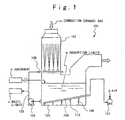
- Fig. 1 shows a first conventional example of the wet type exhaust gas desulfurization apparatus.
- the first conventional example of the wet type exhaust gas desulfurization apparatus [101] is provided with an absorption tower [102] which carries out a wet type desulfurization, and a liquid reservoir [103] is arranged below the absorption tower [102] to reserve alkaline absorption liquid [a].
- Alkali absorbent [b] such as lime is introduced into the absorption liquid[a].
- the absorption liquid [a] is pumped up into the absorption tower [102] through a pipe [105] by a circulation pump [104] and is sprayed by spray pipes [106].
- Combustion exhaust gas [c] is introduced from the top of the absorption tower [102], contacts the sprayed alkali absorption liquid [a].
- sulphur dioxide gas in the exhaust gas reacts with the alkaline absorbent and is changed into sulfite.
- the sulfite is absorbed by the absorption liquid and falls into the liquid reservoir [103] and is collected therein.
- Air [d] is spouted into the absorption liquid [a]containing the sulfite by a blower [107].
- the blower [107] is connected with a plurality of nozzle headers [108] which are arranged in the bottom of the liquid reservoir [103].
- the air is spouted into the absorption liquid [a] from a discharge port [110] provided at the tip of an air supply nozzle [109] extending from each nozzle header [108].
- the sulfite in the absorption liquid[a] reacts with the spouted air and is changed to sulfate.
- the sulfate stoichiometrically equivalent to the sulphur dioxide absorbed in the absorption liquid [a] is discharged as waste fluid [e].
- Absorption efficiency in the oxidation technique by the above air blowing method is mainly influenced based on the contact area between air and the absorption liquid.
- Fig. 2 shows a second conventional example of the wet type exhaust gas desulfurization apparatus [111].
- the wet type exhaust gas desulfurization apparatus [111] is composed of stirrer [112].
- the stirrer [112] has stirring wings [113], and the stirring wings [113] are rotated in the absorption liquid of the liquid reservoir [103].
- the air is supplied by a blower [107] and spouted into the absorption liquid [a] from a discharge port [114] arranged in the front of the stirring wings [113].
- the spouted air accompanies a spouted stream generated by the stirring wing [113] and is distributed into the absorption liquid [a]. This technique can promote the oxidation reaction by the distribution of air.
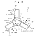
- JP-A-Heisei 4-137731 shows a third conventional example of the wet type exhaust gas desulfurization apparatus [121] shown in Fig. 3.
- a plurality of jet nozzles [117] are provided to generate jet streams [116] in a predetermined angle into the radial directions of the liquid reservoir [115].
- the plurality of jet streams [116] are provided at a predetermined height, and the jet stream from the jet nozzle [117] turns to the circumferential direction of the liquid reservoir [115].
- An absorption liquid pipe [119] is arranged in the bottom of the jet nozzle [117] to pass through the liquid reservoir [115], and a jet stream pump [118] is provided on the way of the pipe [119].
- the opening of an air supply pipe [120] is provided on the way of the absorption liquid pipe [119]. Air [d] is sucked from the air supply pipe [120] by the absorption liquid flowing though the absorption liquid pipe [119] and is spouted into the liquid reservoir [115] from the jet nozzles [117] together with the absorption liquid [a]. This technique can promote the mixing of the absorption liquid and the air more.
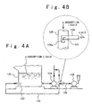
- FIG. 4A shows a fourth conventional example of the wet type exhaust gas desulfurization apparatus [131].
- a discharge pipe [122] penetrates the circumferential wall of the liquid reservoir [123]. Absorption liquid is sucked from a liquid reservoir [123] by a liquid pump [124] and circulated through a circulation liquid pipe [125] and a discharge pipe [122].
- the end of the air blow pipe [126] is inserted into the circulation liquid pipe [125] on the way of circulation liquid pipe [125].
- the direction [127] of an air output portion [126a] of the air blow pipe [126] is almost coincident with the flowing direction of the absorption liquid in the circulation liquid pipe [125].
- the air is pressurized by a blower [128] and is outputted from the end of the air blow pipe [126] into the direction [127]. In this way, the air is mixed with the absorption liquid [a] in the circulation liquid pipe [125] and is spouted from a discharge pipe [122] in the absorption liquid in the liquid reservoir [123].
- the first to fourth conventional examples are superior in the oxidation promotion but the following problems are remained.
- the rising stream is generated due to air lift operation which accompanies the spouting of the air from the discharge port [114].
- the rising stream promotes a narrow region circulation in which the stirring wing [113] absorbs and stirs a part of the liquid again.
- the outreach of the stirred liquid stream becomes short and the stirring efficiency decreases.
- air is supplied from the way of the jet nozzle [117] or absorption liquid pipe [119] which is connected with the discharge pipe 122 or circulation liquid pipe [125]. Therefore, while air bubbles flow through the absorption liquid pipe [119] or circulation liquid pipe [125] together with the liquid, the air bubbles combine and enlarge. As a result, the jet stream is separated into an air phase and an absorption liquid phase. Even if the mixture stream of the air and the liquid is spouted from the jet nozzle [117] or discharge pipe [122] in such a condition, the air bubbles are not uniformly distributed and the perfect oxidation is difficult. Also, the inside of the pipe becomes easy for cavitation erosion.
- an object of the present invention is to provide a wet type exhaust gas desulfurization apparatus and a wet type flue gas desulfurization method in which the contact area between liquid and air can be increased largely.
- Another object of the present invention is to provide a wet type exhaust gas desulfurization apparatus and a wet type flue gas desulfurization method, in which air and absorption liquid are sufficiently stirred and can be distributed.
- Still another object of the present invention is to provide a wet type exhaust gas desulfurization apparatus and a wet type flue gas desulfurization method, in which the number of air supply nozzles can be decreased largely, so that power can be reduced.
- Yet still another object of the present invention is to provide a wet type exhaust gas desulfurization apparatus and a wet type flue gas desulfurization process method, in checking work can be made easy through the simplification of the structure of the liquid reservoir.
- a wet type exhaust gas desulfurization apparatus includes a liquid reservoir which reserves absorption liquid containing absorbent, wherein sulfite is contained in the absorption liquid; a sulfur dioxide removing system which removes sulphur dioxide from combustion exhaust gas and forms sulfite; and an air supplying and circulating system which has a reduction section, and which supplies air to the liquid reservoir using a negative pressure generated due to the reduction section to oxidize the sulfite.
- the air supplying and circulating system may include a nozzle, wherein a discharge port of the nozzle is opened in the absorption liquid of the liquid reservoir; a first pump which circulatively supplies the absorption liquid in the liquid reservoir to the nozzle; a pipe which connects the nozzle and a side of the discharging port of the first pump; the reduction section arranged between the pipe and the nozzle; and an air suction pipe arranged on a downstream side from the reduction section and connected with the nozzle.
- the reduction section has a reduction section hole which has an effective cross section narrower than an effective cross section of the pipe. The air is sucked through the air suction pipe, flows in the nozzle with the absorption liquid, and is spouted into the absorption liquid of the liquid reservoir to oxidize the nitrite.
- a distance between a center line of the reduction section in a direction orthogonal to a direction of a flow path in the nozzle and a center line of the air suction pipe is shorter than twice of an effective diameter of an absorption liquid spouting stream path in the nozzle.
- the effective diameter of the reduction section hole is set to a range of 0.5 to 0.8 times of the effective diameter of the absorption liquid spouting stream path.
- the internal circumference surface of the reduction section hole has smoothly increased diameter in a direction of a downstream side. Also, it is desirable that an opening peripheral portion of the reduction section hole on the upstream side sharply sticks out into a direction of the upstream side.
- the nozzle may have an extension pipe, and it is desirable that the extension pipe extends from outside of the liquid reservoir into the absorption liquid in the liquid reservoir.
- a central axis of a flow path formed in the nozzle is inclined with respect to a liquid surface in the liquid reservoir.
- the air suction pipe is connected with the nozzle in a one end and is opened into atmosphere in the other end.
- the air suction pipe has an upper portion and a lower portion, and the lower portion is fixed on the nozzle and the upper portion is supported by the lower portion movably in upper and lower directions.
- the opening of the air suction pipe opened to the atmosphere is set to a position higher than the liquid surface of the absorption liquid in the liquid reservoir, when the pump stops.
- the nozzle may includes a lower pipe provided on a downstream side from the reduction section; and an extension pipe connected with the lower pipe on a downstream side, and it is desirable that the extension pipe is fixed to the liquid reservoir and the lower pipe is connected with the extension pipe detachably.
- the sulphur dioxide removing system may include an absorption tower in which the combustion exhaust gas containing the sulphur dioxide is introduced; a spray pipe provided in a lower portion of the absorption tower; and a second pump which supplies the absorption liquid from the liquid reservoir to the spray pipe such that the absorption liquid is sprayed from the spray pipe into the absorption tower.
- a wet type exhaust gas desulfurization method is achieved by sucking liquid in a liquid reservoir containing chemical substance as an oxidation object and forming a flow of the liquid; by reducing the flow of the liquid in diameter; by introducing air into a negative pressure region generated due to the reduction to generate a mixture stream of air and liquid; and by spouting the mixture stream into the liquid reservoir.
- a spouting direction turns down with respect to a liquid surface of said liquid reservoir.
- Fig. 5 shows the wet type exhaust gas desulfurization apparatus according to the first embodiment of the present invention.
- an absorption tower [1] is provided together with a liquid reservoir [2] to carry out a wet type desulfurizing process.
- the absorption tower [1] is arranged above the liquid reservoir [2].
- Water is introduced into the liquid reservoir [2].
- Absorbent [a] is introduced into the water from the water surface through a pipe [3]
- the absorption liquid [b] is formed of the water and the absorbent [a].
- spray pipes [4] are arranged in the lower portion of the absorption tower [1].
- a lot of the absorption liquid discharge ports [5] are provided for the spray pipes [4] to spray the absorption liquid into the upper direction in the tower [1].
- the lower portion of the absorption tower [1] is opened, the inner space of the absorption tower [1] is connected with the upper portion of the inner space of the liquid reservoir [2].
- a circulation pipe [6] is arranged between the liquid reservoir [2] and the spray pipes [4] to circulate the absorption liquid [b].
- a circulation pump [7] is interposed in the pipe [6].
- the absorption liquid in the liquid reservoir [2] is pumped up by the circulation pump [7] and is spouted from the absorption liquid discharge ports [5] of the spray pipes [4]. A part of the absorption liquid [b] which is pumped up by the circulation pump [7] is discharged as waste fluid [c].
- An uptake [8] is provided in the upper portion of the liquid reservoir [2].
- the region under the uptake [8] extends to the inner space of the liquid reservoir [2].
- the combustion exhaust gas [d] is exhausted from a combustion equipment (not shown) like a boiler and is introduced from an upper introduction port [9] of the absorption tower [1] thereinto.
- the combustion exhaust gas after sulphur dioxide gas is removed is exhausted from the end of the uptake [8] into the atmosphere as a cleaned exhaust gas [e].
- a nozzle [11] is arranged in the bottom of the liquid reservoir [2] to penetrate the circumferential wall of the liquid reservoir [2], A discharge port [12] is formed at the tip of the nozzle [11].
- the absorption liquid [a] is sucked up from the liquid reservoir [2], and spouted from the nozzle [11] through a pipe [15].
- the nozzle [11] has a reduction section [14].
- the reduction section [14] and the discharge side of the pump [13] are connected by the pipe [15].
- a pipe [41] is provided on the downstream side of the reduction section [14] into a direction of the discharge port [12] of the nozzle [11].
- a long extension pipe [42] is connected with the pipe [41] by joining flanges [43].
- the discharge port [12] is formed as an opening at the tip of the extension pipe [42].
- the extension pipe [42] extends to form an absorption liquid spouting stream path [16] formed as an inner flow path in the nozzle [111] into the liquid reservoir [2].
- An air suction pipe [17] is connected with the pipe [41] in which the absorption liquid spouting stream path [16] is formed.
- the air suction pipe [17] has an opening [18] on the downstream side of the reduction section [14] for the absorption liquid spouting stream path [16].
- the air suction pipe [17] has the opening in the circumferential surface portion of the pipe [41] on the downstream side of the reduction section [14],
- the other end of the air suction pipe [17] has an opening [19] opened to the atmosphere.
- the height position of the opening [19] is set to be higher than the liquid surface of the liquid reservoir [2].
- the central axis [L] of the absorption liquid spouting stream path [16] is inclined with respect to the horizontal plane by about 10 degrees so that the downstream side is lower than the upstream side.
- the reduction section [14] has a flange [21] on the side of the pipe [15], a flange [22] on the side of the discharge port [12] and a reduction section plate [23].
- the reduction section plate [23] has a reduction section hole [24].
- the central axis of the reduction section hole [24] in the direction of the spouting stream path is coincident with the central axis [L] of the spouting stream path.
- the size of the reduction section hole [24] is properly designed based on the variables and constants such as the cross section of the absorption liquid spouting stream path [16], the spouting stream rate per a unit time of the pump [13].
- the alkali absorption liquid [b] is sucked by a circulation pump [7], is pumped up onto the spray pipes [4] and is sprayed from the plurality of absorption liquid discharge ports [5] of the spray pipes [4] in an almost straightly upward direction.
- the lime component of the sprayed alkali absorption liquid [b] contacts and reacts with sulphur dioxide gas of the combustion exhaust gas [d] introduced from the upper end introduction port [9] of the absorption tower [1].
- the sulphur dioxide is changed to sulfite.
- the cleaned exhaust gas [e] after the sulphur dioxide is removed passes through the uptake [8] and is discharged outside.
- the absorption liquid [b] containing the sulfite becomes shaped like liquid drops and falls down into the liquid reservoir [2] in accordance with gravitation.
- the mixture steam of air and absorption liquid is spouted from the discharge port [12] of the nozzle [11] into the liquid reservoir [2] as described later.
- the sulfite in the absorption liquid contacts air, is oxidized and changed to sulfate.
- the absorption liquid containing a high concentration of sulfate is discharged as waste fluid [c].
- the absorbent [a] such as lime is supplemented into the liquid reservoir [2].
- the mixture steam of the air and liquid spouted from the nozzle [11] is generated in the neighborhood of the opening [18] of the air suction pipe 17].
- the flow [A] of the absorption liquid discharged from the pump [13] receives resistance of the reduction section plate [23] of the reduction section [14], passes through the reduction section hole [24], and flows into the neighborhood of the opening [18] as a flow [B], as shown in Fig. 6. Therefore, a negative pressure region is generated in the neighborhood of the opening [18]. That is, the pressure in the neighborhood of the opening [18] is more decreased than the pressure in the opening [19].
- the air flows into the depressurized region forcefully as an air stream [C] through the air suction pipe [17],
- the flow [B] of the absorption liquid is changed into a turbulent stream, and is stirred, and the air stream [C] is joined to the flow [B] of the absorption liquid.
- the air stream is changed to the flow of minute air bubbles by the contraction stream peeling effect.
- the combination and enlargement of the air bubbles is more effectively prevented if the diameter of the minute air bubble is smaller.
- the mixture stream of air and liquid in the absorption liquid spouting stream path [16] in the nozzle [11] keeps such a turbulent stream stirring characteristic.
- the mixture stream of air and liquid is spouted from the discharge port [12] of the nozzle [11] into the absorption liquid in the liquid reservoir [2] as a bubble stream.
- a bubble stream is spouted as a liquid stream with the inclination of about 10 degrees, and flows along the bottom surface of the liquid reservoir [2] and reaches a distant place. Because the bubble stream is fast, the bubble stream reaches the distant place before the air bubbles are combined. At this time, the air bubbles float up to the surface of the absorption liquid [a] while keeping the minute air bubble state. Therefore, the minute air bubbles contact the absorption liquid with a large contact area to promote the oxidation of sulfite.
- the absorption liquid passes through the reduction section holes [24] of the reduction section [14], the negative pressure region is generated on the downstream side from the reduction section [14] due to the absorption liquid contraction stream peeling effect.
- the air is sucked from the opening of the air suction pipe [17] to the negative pressure region in correspondence to the negative pressure generated by the flow of the absorption liquid.
- the sucked air is mixed with the absorption liquid stream [B] to produce the mixture stream of air and liquid.
- the mixture stream of air and liquid is spouted from the discharge port [12] of the nozzle [11] into the absorption liquid [a] in the liquid reservoir [2] as a strong jet stream. At this time, the mixture stream of air and liquid receives a dispersion effect from the absorption liquid [a].
- the mixture stream of air and liquid forms a large stream in the absorption liquid [a] in the liquid reservoir [2], accompanied by a wake.
- a mixture stream of air and liquid accompanied by the wake has large momentum, and is distributed in the wide region of the liquid reservoir [2].
- the region where the mixture stream of air and liquid is spouted and the absorption liquid a accompanies the mixture stream is effective to the distance which is determined based on the discharging diameter and discharging pressure of the mixture stream of air and liquid, and the density of the absorption liquid [a] from the discharge port [12]. Therefore, narrow region circulation does not occur.
- the air bubbles in the mixture stream of air and liquid accompanied by the wake are distributed into the discharging direction while being forcefully confined in the wake. Thus, it is effectively prevented that the air bubbles combine with each other to produce a large air bubble.
- the air is sucked using the negative pressure region which is formed on the way of the discharging nozzle for generating the jet stream, unlike the third and fourth conventional examples in which the air is mixed on the sufficiently upstream side from the discharging nozzle [4].
- the mixture stream of air and liquid is formed.
- the air is sucked based on the difference between the pressure in the negative pressure region and the atmospheric pressure, and is sheared by the flow of the absorption liquid to produce a lot of minute air bubbles. In this way, the mixture stream of air and liquid is formed.
- the air bubbles taken into the absorption liquid a receive shearing stress not after spouting but in the discharging nozzle, and is changed into the minute air bubbles which are distributed.
- the air bubbles made in this way are forcefully spouted outside the discharging nozzle, and are carried to the distant place in the large flow accompanied by the wake, while keeping the minute bubble state. Therefore, the combination of the air bubbles does not occur in the pipe [42], and the air bubbles are distributed in the wide region of the absorption liquid. Also, there is no case that the separation of air and the absorption liquid occurs to produce a 2-phase stream.
- the height of the liquid surface [31] of the absorption liquid [b] in the liquid reservoir [2] was set to about 2.5 m from the bottom.
- a relative height between a liquid suck port [32] provided on the side wall of the liquid reservoir [2] for the pump [13] and the liquid surface [31] was set to 2 m.
- the horizontal position of the discharge port [12] was set to 0.4 m from the inner surface of the side wall where the liquid suck port [32] was opened.
- the circulation pipe [6] was used to suck the absorption liquid of 200 cubic meters per an hour.
- the air suction pipe [17] sucked the air of 180 cubic meters N per an hour from the opening [19].
- the combustion exhaust gas [d] of 40,000 cubic meters N per an hour containing about 1,000-ppm SO 2 was introduced into the absorption tower [1].
- the absorption liquid [b] 500 cubic meters per an hour was pumped up by the circulation pump [7] and was sprayed from the spray pipes [4] into the absorption tower [1].
- the combustion exhaust gas [d] was subjected to a desulfurization process. Sulphur dioxide gas SO 2 reacted with the absorbent [a] (lime) which is stoichiometrically equivalent to the sulphur dioxide and the absorption liquid containing gypsum was discharged as waste fluid [c],
- the distance between the center line of the air suction pipe [17] and the reduction plate [23] of the reduction section [14] in a plane direction is properly defined in accordance with hydrodynamics. It is desirable that the distance is shorter than twice of the diameter of the nozzle [11] (which is the diameter of the absorption liquid spouting stream path [16], especially, the diameter on the circular conversion of the effective cross section of the absorption liquid spouting stream path [16]). If it is considered that the air can be efficiently sucked and the spouting stream can reach a distant place, it is desirable that the diameter of the reduction section hole [24] as a reduction diameter is 0.5 to 0.8 times of the diameter of the nozzle [11]. Such definition is a guideline that the generation of the negative pressure region on the downstream side from the reduction section [14] becomes effective according to the flow in the pipe [15] in case of experiment. When the distance is long, the negative pressure region cannot be generated effectively.
- a long extension pipe [42] is connected with the pipe [41] on the downstream side of the nozzle [11] between the reduction section [14] and the discharge port [12] by a joining flange section [43].
- the discharging port [12] is formed as an opening at the tip of the extension pipe [42].
- the extension pipe [42] elongates the absorption liquid spouting stream path [16] and passes through the side wall of the liquid reservoir [2].
- the air suction pipe [17] is connected with the pipe [41] for the absorption liquid spouting stream path [16].
- the air suction pipe [17] has an opening [18] for the absorption liquid spouting stream path [16] on the downstream side from the reduction section [14].
- the air suction pipe [17] has the opening in the circumferential surface portion of the pipe [41] on the downstream side.
- An opening [19] to the atmosphere is formed at the other end of the air suction pipe [17].
- the height position of the opening [19] is set to higher than the liquid surface [31] of the liquid reservoir [2].
- the central axis [L] of the absorption liquid spouting stream path [16] formed as a flow path in the nozzle [11] inclines with respect to the horizontal plane by about 10 degrees and the downstream side is lower than the upstream side.
- the reduction section [14] has a flange [21] on the side of the pipe [15], a flange [22] on the side of the discharge port [12] and a reduction section plate [23].
- the reduction section plate [23] has a reduction section hole [24].
- the center line of the reduction section hole [24] in the stream direction is coincident with the central axis [L] of the absorption liquid spouting stream path [16].
- the size of the reduction section hole [24] is properly designed based on constants and variables such as the cross section of the absorption liquid spouting stream path [16], and the discharging flow rate per a unit time of the pump [13].
- the air suction pipe [17] is formed as a double pipe and is composed of a fixed pipe [17a] and a movable pipe [17b].
- the movable pipe is drawn up to a sufficiently high position such that the absorption liquid does not overflow. Because the liquid surface is lowered due to the absorption liquid discharging stream while the pump [13] is driven, the movable pipe [17b] is lowered to a lower position.
- the full length of the air suction pipe [17] becomes short and the resistance of the internal circumference surface of the air suction pipe [17] becomes small in case of the suction of air from the opening [19] of the air suction pipe [17].
- the flanges [41a] and [42a] for joining the pipe [41] and the extension pipe [42] in the nozzle [11] are assembled detachably.
- a plurality of thick portions of the flange [41a] on the side of the pipe [41] are engaged with a plurality of ditch portions of the flange [42a] on the side of the extension pipe [42].
- the extension pipe [42] is always mounted to the liquid reservoir [2].
- the unit containing the pipe [41] and the reduction section [14] is mounted to the extension pipe [42] detachably.
- the reduction section [14] is replaceable.
- the reduction section plate [23] has the reduction section hole [24].
- the opening peripheral portion of the reduction section hole [24] has a portion protruding to the upstream side. In this way, the opening peripheral portion has a sharp angle at the tip on the upstream side and an un-sharp shape on the downstream side.
- the opening peripheral portion has the diameter increasing from the upstream side [23a] to the downstream side [23b]. That is, the internal circumference surface of the upstream side [23a] and the internal circumference surface of the downstream side [23b] form a continuously smooth and curved surface.
- the curved surface is formed like the cone surface of horn (or the quasi-cone surface). The cone surface becomes continuously larger in diameter in the opening of the downstream side rather than the opening of the upstream side.
- the tip of the reduction section [24] on the upstream side protrudes more on the side opposite to the opening [19] of the air suction pipe [17] than on the side of the opening [19] of the air suction pipe [17].
- the absorption liquid stream in the pipe [15] is sheared and peeled off in the upstream side [23a] and minute cavities are innumerably formed in the upstream side [23a]. Moreover, such a large amount of minute cavities are dispersed in the absorption liquid stream which undergoes the negative pressure. The minute cavities are dispersed in this way. Moreover, the air bubbles introduced from the air suction pipe [17] into the absorption liquid stream under the negative pressure are effectively absorbed and dispersed in the absorption liquid.
- the contact region of the air and the liquid becomes uniformly wide regardless of position due to synergy effect of the wide region and the mixed phases. There is no ununiformity of the oxidation depending on the position and the perfect oxidation or approximately perfect oxidation can be realized.
Landscapes
- Chemical & Material Sciences (AREA)
- Engineering & Computer Science (AREA)
- Analytical Chemistry (AREA)
- General Chemical & Material Sciences (AREA)
- Oil, Petroleum & Natural Gas (AREA)
- Chemical Kinetics & Catalysis (AREA)
- Health & Medical Sciences (AREA)
- Biomedical Technology (AREA)
- Environmental & Geological Engineering (AREA)
- Treating Waste Gases (AREA)
- Chimneys And Flues (AREA)
- Nozzles (AREA)
Applications Claiming Priority (5)
| Application Number | Priority Date | Filing Date | Title |
|---|---|---|---|
| JP2000351802 | 2000-11-17 | ||
| JP2000351802 | 2000-11-17 | ||
| JP2001275254 | 2001-09-11 | ||
| JP2001275254A JP3854481B2 (ja) | 2000-11-17 | 2001-09-11 | 湿式排煙脱硫装置、及び、湿式排煙脱硫方法 |
| PCT/JP2001/009954 WO2002040137A1 (en) | 2000-11-17 | 2001-11-14 | Method and apparatus for wet type flue-gas desulfurizaion |
Publications (3)
| Publication Number | Publication Date |
|---|---|
| EP1243308A1 EP1243308A1 (en) | 2002-09-25 |
| EP1243308A4 EP1243308A4 (en) | 2003-04-23 |
| EP1243308B1 true EP1243308B1 (en) | 2006-05-31 |
Family
ID=26604233
Family Applications (1)
| Application Number | Title | Priority Date | Filing Date |
|---|---|---|---|
| EP01982780A Expired - Lifetime EP1243308B1 (en) | 2000-11-17 | 2001-11-14 | Apparatus for wet type flue-gas desulfurization |
Country Status (7)
| Country | Link |
|---|---|
| US (2) | US6787114B2 (da) |
| EP (1) | EP1243308B1 (da) |
| JP (1) | JP3854481B2 (da) |
| CN (1) | CN1198678C (da) |
| DK (1) | DK1243308T3 (da) |
| ES (1) | ES2263673T3 (da) |
| WO (1) | WO2002040137A1 (da) |
Cited By (1)
| Publication number | Priority date | Publication date | Assignee | Title |
|---|---|---|---|---|
| DE102013225615A1 (de) * | 2013-12-11 | 2015-06-11 | Ksb Aktiengesellschaft | Rauchgasentschwefelung |
Families Citing this family (25)
| Publication number | Priority date | Publication date | Assignee | Title |
|---|---|---|---|---|
| US6695018B2 (en) * | 2002-06-10 | 2004-02-24 | The Babcock & Wilcox Company | Collection scoop for flue gas desulfurization systems with bleed streams or ex situ forced oxidation |
| WO2006121656A2 (en) * | 2005-05-05 | 2006-11-16 | Merck & Co., Inc. | Peptide conjugate compositions and methods for the prevention and treatment of alzheimer's disease |
| JP5259964B2 (ja) * | 2007-02-28 | 2013-08-07 | 三菱重工業株式会社 | 海水排煙脱硫システム |
| US8540219B2 (en) | 2007-03-16 | 2013-09-24 | Alstom Technology Ltd | System and method for preventing scaling in a flue gas desulphurization system |
| CN102145247B (zh) * | 2010-02-09 | 2013-07-31 | 成都华西工业气体有限公司 | 溶剂循环吸收法烟气脱硫中脱硫溶剂的净化工艺 |
| US9028762B2 (en) | 2012-07-30 | 2015-05-12 | Mitsubishi Hitachi Power Systems, Ltd. | Wet type exhaust gas desulfurization apparatus |
| JP5892265B2 (ja) * | 2012-12-19 | 2016-03-23 | 富士電機株式会社 | 排ガス浄化装置 |
| US9157032B2 (en) | 2013-02-19 | 2015-10-13 | Uop Llc | Process for oxidizing one or more thiol compounds |
| AU2013394505B2 (en) | 2013-07-17 | 2017-03-23 | Mitsubishi Heavy Industries, Ltd. | Water treatment device |
| CN103566744B (zh) * | 2013-11-21 | 2015-11-04 | 航天环境工程有限公司 | 烧结机气液混合式湿式排烟脱硫装置 |
| CN103566748B (zh) * | 2013-11-21 | 2015-06-17 | 航天环境工程有限公司 | 烧结机搅拌式湿式排烟脱硫装置 |
| CN104740950A (zh) * | 2013-12-25 | 2015-07-01 | 贵阳活性源环保产业有限公司 | 一种油辣椒加工油烟废气净化方法 |
| KR101612519B1 (ko) * | 2014-05-13 | 2016-04-14 | 이진환 | 집진장치 |
| CN104874274B (zh) * | 2015-05-12 | 2017-12-12 | 江苏揽山环境科技股份有限公司 | 一种氧化池 |
| CN105413428B (zh) * | 2015-11-27 | 2018-05-04 | 攀钢集团攀枝花钢铁研究院有限公司 | 有机胺法烟气脱硫工艺 |
| CN106371140B (zh) * | 2016-08-17 | 2018-05-29 | 中国石油化工股份有限公司 | 一种提高中深层地震资料分辨率的方法 |
| TW201834735A (zh) * | 2017-03-21 | 2018-10-01 | 大陸商昆山納諾新材料科技有限公司 | 應用奈米微氣泡的廢氣處理方法及其廢氣處理系統 |
| US11065576B2 (en) * | 2018-01-19 | 2021-07-20 | Doosan Heavy Industries & Construction Co., Ltd. | Wet flue gas desulfurization apparatus |
| JP6553277B1 (ja) * | 2018-12-11 | 2019-07-31 | 三菱日立パワーシステムズ株式会社 | 気液混合装置、および気液混合装置を備える排ガス脱硫装置 |
| JP6588147B1 (ja) * | 2018-12-11 | 2019-10-09 | 三菱日立パワーシステムズ株式会社 | 排ガス脱硫装置 |
| JP6559873B1 (ja) * | 2018-12-11 | 2019-08-14 | 三菱日立パワーシステムズ株式会社 | 気液混合装置、および気液混合装置を備える排ガス脱硫装置 |
| CN113399412B (zh) * | 2021-05-22 | 2023-04-14 | 北京阿玛西换热设备制造有限公司 | 一种市政用河道废气收集装置 |
| CN116351229B (zh) * | 2023-03-14 | 2023-10-17 | 汇舸(南通)环保设备有限公司 | 一种喷淋式脱硫设备 |
| CN117065535B (zh) * | 2023-09-28 | 2024-05-31 | 深圳易普乐环保科技有限公司 | 复配式微生物发酵废气处理系统 |
| TWI901365B (zh) * | 2024-09-26 | 2025-10-11 | 國立高雄科技大學 | 兼具多功能實質環保效益的船舶專用脫硫系統及其裝置 |
Family Cites Families (10)
| Publication number | Priority date | Publication date | Assignee | Title |
|---|---|---|---|---|
| US4483805A (en) * | 1982-06-09 | 1984-11-20 | Adl-Innovation Kb | Process for injection of fluid, e.g. slurry in e.g. flue gases and a nozzle device for the accomplishment of the process |
| JPS62194423A (ja) | 1986-02-20 | 1987-08-26 | Fujitsu Ltd | レ−ザ線幅測定装置 |
| JPS62194423U (da) * | 1986-05-29 | 1987-12-10 | ||
| JPH04137731A (ja) | 1990-09-28 | 1992-05-12 | Fujitsu Ltd | 半導体装置の製造方法 |
| US5209905A (en) | 1990-12-14 | 1993-05-11 | Mitsubishi Jukogyo Kabushiki Kaisha | Wet-type exhaust gas desulfurization system having a means for supplying air |
| JPH05285331A (ja) | 1992-04-06 | 1993-11-02 | Ishikawajima Harima Heavy Ind Co Ltd | 吸収塔空気吹込み装置 |
| JPH0731841A (ja) | 1993-07-23 | 1995-02-03 | Ishikawajima Harima Heavy Ind Co Ltd | 脱硫装置 |
| JPH08950A (ja) | 1994-06-20 | 1996-01-09 | Ishikawajima Harima Heavy Ind Co Ltd | 気体吹込装置 |
| TW402520B (en) * | 1997-11-05 | 2000-08-21 | Mitsubishi Heavy Ind Ltd | Wet flue gas desulfurizer and oxygen-containing gas blowing device for use therein |
| KR100366159B1 (ko) | 1998-08-11 | 2003-01-09 | 미츠비시 쥬고교 가부시키가이샤 | 습식 배연 탈황 장치 |
-
2001
- 2001-09-11 JP JP2001275254A patent/JP3854481B2/ja not_active Expired - Lifetime
- 2001-11-14 US US10/169,080 patent/US6787114B2/en not_active Expired - Lifetime
- 2001-11-14 EP EP01982780A patent/EP1243308B1/en not_active Expired - Lifetime
- 2001-11-14 DK DK01982780T patent/DK1243308T3/da active
- 2001-11-14 CN CNB01803828XA patent/CN1198678C/zh not_active Expired - Lifetime
- 2001-11-14 WO PCT/JP2001/009954 patent/WO2002040137A1/ja not_active Ceased
- 2001-11-14 ES ES01982780T patent/ES2263673T3/es not_active Expired - Lifetime
-
2004
- 2004-05-24 US US10/851,331 patent/US6932952B2/en not_active Expired - Lifetime
Cited By (2)
| Publication number | Priority date | Publication date | Assignee | Title |
|---|---|---|---|---|
| DE102013225615A1 (de) * | 2013-12-11 | 2015-06-11 | Ksb Aktiengesellschaft | Rauchgasentschwefelung |
| DE102013225615B4 (de) | 2013-12-11 | 2022-01-20 | KSB SE & Co. KGaA | Vorrichtung und Verfahren zur Rauchgasentschwefelung |
Also Published As
| Publication number | Publication date |
|---|---|
| ES2263673T3 (es) | 2006-12-16 |
| EP1243308A1 (en) | 2002-09-25 |
| WO2002040137A1 (en) | 2002-05-23 |
| CN1198678C (zh) | 2005-04-27 |
| JP2002210326A (ja) | 2002-07-30 |
| DK1243308T3 (da) | 2006-09-18 |
| EP1243308A4 (en) | 2003-04-23 |
| US6932952B2 (en) | 2005-08-23 |
| US6787114B2 (en) | 2004-09-07 |
| US20030012706A1 (en) | 2003-01-16 |
| CN1395499A (zh) | 2003-02-05 |
| US20040213722A1 (en) | 2004-10-28 |
| JP3854481B2 (ja) | 2006-12-06 |
Similar Documents
| Publication | Publication Date | Title |
|---|---|---|
| US6787114B2 (en) | Method and apparatus for wet type flue-gas desulfurization | |
| KR100366159B1 (ko) | 습식 배연 탈황 장치 | |
| EP1958682B1 (en) | Wet flue-gas desulfurization apparatus and method of wet flue-gas desulfurization | |
| US6190620B1 (en) | Wet flue gas desulfurizer | |
| US11065576B2 (en) | Wet flue gas desulfurization apparatus | |
| JPWO2000009243A1 (ja) | 湿式排煙脱硫装置 | |
| WO1995034370A1 (en) | Gas-liquid contact gas dispersion pipe, and gas-liquid contact method and apparatus using the same | |
| CN105169926A (zh) | 一种烟气脱硫系统及利用其进行烟气脱硫的方法 | |
| EP1972368B1 (en) | System & method for preventing scaling in a gas desulphurization system | |
| JP3382837B2 (ja) | 排煙脱硫装置の空気吹込み装置 | |
| JP3842706B2 (ja) | 湿式排煙脱硫装置と方法 | |
| JP2008068161A (ja) | 湿式排煙脱硫装置 | |
| KR0135324B1 (ko) | 배연탈황 공정의 공기공급 교반장치 | |
| JPH02111420A (ja) | 湿式排煙脱硫装置 | |
| JPH10113534A (ja) | 排煙処理装置 | |
| JPH08215532A (ja) | ガス吸収装置 | |
| JP2001276553A (ja) | 湿式ガス吸収塔の吸収剤供給方法及びその装置 | |
| HK1029543B (en) | Wet type flue gas desulfurization equipment | |
| HK1018752B (en) | Wet flue gas desulfurizer and oxygen-containing gas blowing device for use therein | |
| PL134353B2 (en) | Mass exchange method and apparatus therefor |
Legal Events
| Date | Code | Title | Description |
|---|---|---|---|
| PUAI | Public reference made under article 153(3) epc to a published international application that has entered the european phase |
Free format text: ORIGINAL CODE: 0009012 |
|
| 17P | Request for examination filed |
Effective date: 20020709 |
|
| AK | Designated contracting states |
Kind code of ref document: A1 Designated state(s): AT BE CH CY DE DK ES FI FR GB GR IE IT LI LU MC NL PT SE TR |
|
| A4 | Supplementary search report drawn up and despatched |
Effective date: 20030312 |
|
| 17Q | First examination report despatched |
Effective date: 20031030 |
|
| RBV | Designated contracting states (corrected) |
Designated state(s): AT BE CH CY DE DK ES GB IT LI TR |
|
| GRAP | Despatch of communication of intention to grant a patent |
Free format text: ORIGINAL CODE: EPIDOSNIGR1 |
|
| RTI1 | Title (correction) |
Free format text: APPARATUS FOR WET TYPE FLUE-GAS DESULFURIZATION |
|
| GRAS | Grant fee paid |
Free format text: ORIGINAL CODE: EPIDOSNIGR3 |
|
| GRAA | (expected) grant |
Free format text: ORIGINAL CODE: 0009210 |
|
| AK | Designated contracting states |
Kind code of ref document: B1 Designated state(s): DK ES GB IT TR |
|
| PG25 | Lapsed in a contracting state [announced via postgrant information from national office to epo] |
Ref country code: IT Free format text: LAPSE BECAUSE OF FAILURE TO SUBMIT A TRANSLATION OF THE DESCRIPTION OR TO PAY THE FEE WITHIN THE PRESCRIBED TIME-LIMIT;WARNING: LAPSES OF ITALIAN PATENTS WITH EFFECTIVE DATE BEFORE 2007 MAY HAVE OCCURRED AT ANY TIME BEFORE 2007. THE CORRECT EFFECTIVE DATE MAY BE DIFFERENT FROM THE ONE RECORDED. Effective date: 20060531 |
|
| RBV | Designated contracting states (corrected) |
Designated state(s): DK ES GB IT TR |
|
| REG | Reference to a national code |
Ref country code: GB Ref legal event code: FG4D |
|
| REG | Reference to a national code |
Ref country code: DE Ref legal event code: 8566 |
|
| REG | Reference to a national code |
Ref country code: DK Ref legal event code: T3 |
|
| REG | Reference to a national code |
Ref country code: ES Ref legal event code: FG2A Ref document number: 2263673 Country of ref document: ES Kind code of ref document: T3 |
|
| PLBE | No opposition filed within time limit |
Free format text: ORIGINAL CODE: 0009261 |
|
| STAA | Information on the status of an ep patent application or granted ep patent |
Free format text: STATUS: NO OPPOSITION FILED WITHIN TIME LIMIT |
|
| 26N | No opposition filed |
Effective date: 20070301 |
|
| PGFP | Annual fee paid to national office [announced via postgrant information from national office to epo] |
Ref country code: DK Payment date: 20141111 Year of fee payment: 14 |
|
| REG | Reference to a national code |
Ref country code: ES Ref legal event code: PC2A Effective date: 20150909 |
|
| REG | Reference to a national code |
Ref country code: GB Ref legal event code: 732E Free format text: REGISTERED BETWEEN 20151203 AND 20151209 |
|
| REG | Reference to a national code |
Ref country code: DK Ref legal event code: EBP Effective date: 20151130 |
|
| PG25 | Lapsed in a contracting state [announced via postgrant information from national office to epo] |
Ref country code: DK Free format text: LAPSE BECAUSE OF NON-PAYMENT OF DUE FEES Effective date: 20151130 |
|
| PGFP | Annual fee paid to national office [announced via postgrant information from national office to epo] |
Ref country code: TR Payment date: 20201112 Year of fee payment: 20 |
|
| PGFP | Annual fee paid to national office [announced via postgrant information from national office to epo] |
Ref country code: ES Payment date: 20201210 Year of fee payment: 20 Ref country code: IT Payment date: 20201013 Year of fee payment: 20 Ref country code: GB Payment date: 20201104 Year of fee payment: 20 |
|
| REG | Reference to a national code |
Ref country code: GB Ref legal event code: PE20 Expiry date: 20211113 |
|
| PG25 | Lapsed in a contracting state [announced via postgrant information from national office to epo] |
Ref country code: GB Free format text: LAPSE BECAUSE OF EXPIRATION OF PROTECTION Effective date: 20211113 |
|
| REG | Reference to a national code |
Ref country code: ES Ref legal event code: FD2A Effective date: 20220225 |
|
| PG25 | Lapsed in a contracting state [announced via postgrant information from national office to epo] |
Ref country code: ES Free format text: LAPSE BECAUSE OF EXPIRATION OF PROTECTION Effective date: 20211115 |