EP1247896A2 - Verfahren und Vorrichtung zur Überwachung der Funktion von Spritzdüsen - Google Patents
Verfahren und Vorrichtung zur Überwachung der Funktion von Spritzdüsen Download PDFInfo
- Publication number
- EP1247896A2 EP1247896A2 EP02002826A EP02002826A EP1247896A2 EP 1247896 A2 EP1247896 A2 EP 1247896A2 EP 02002826 A EP02002826 A EP 02002826A EP 02002826 A EP02002826 A EP 02002826A EP 1247896 A2 EP1247896 A2 EP 1247896A2
- Authority
- EP
- European Patent Office
- Prior art keywords
- spray
- jet
- spray jet
- measuring arrangement
- nozzles
- Prior art date
- Legal status (The legal status is an assumption and is not a legal conclusion. Google has not performed a legal analysis and makes no representation as to the accuracy of the status listed.)
- Withdrawn
Links
Images
Classifications
-
- B—PERFORMING OPERATIONS; TRANSPORTING
- B05—SPRAYING OR ATOMISING IN GENERAL; APPLYING FLUENT MATERIALS TO SURFACES, IN GENERAL
- B05B—SPRAYING APPARATUS; ATOMISING APPARATUS; NOZZLES
- B05B12/00—Arrangements for controlling delivery; Arrangements for controlling the spray area
- B05B12/004—Arrangements for controlling delivery; Arrangements for controlling the spray area comprising sensors for monitoring the delivery, e.g. by displaying the sensed value or generating an alarm
-
- B—PERFORMING OPERATIONS; TRANSPORTING
- B05—SPRAYING OR ATOMISING IN GENERAL; APPLYING FLUENT MATERIALS TO SURFACES, IN GENERAL
- B05B—SPRAYING APPARATUS; ATOMISING APPARATUS; NOZZLES
- B05B15/00—Details of spraying plant or spraying apparatus not otherwise provided for; Accessories
- B05B15/50—Arrangements for cleaning; Arrangements for preventing deposits, drying-out or blockage; Arrangements for detecting improper discharge caused by the presence of foreign matter
-
- D—TEXTILES; PAPER
- D21—PAPER-MAKING; PRODUCTION OF CELLULOSE
- D21F—PAPER-MAKING MACHINES; METHODS OF PRODUCING PAPER THEREON
- D21F1/00—Wet end of machines for making continuous webs of paper
- D21F1/32—Washing wire-cloths or felts
-
- D—TEXTILES; PAPER
- D21—PAPER-MAKING; PRODUCTION OF CELLULOSE
- D21F—PAPER-MAKING MACHINES; METHODS OF PRODUCING PAPER THEREON
- D21F1/00—Wet end of machines for making continuous webs of paper
- D21F1/34—Construction or arrangement of spraying pipes
-
- B—PERFORMING OPERATIONS; TRANSPORTING
- B05—SPRAYING OR ATOMISING IN GENERAL; APPLYING FLUENT MATERIALS TO SURFACES, IN GENERAL
- B05B—SPRAYING APPARATUS; ATOMISING APPARATUS; NOZZLES
- B05B12/00—Arrangements for controlling delivery; Arrangements for controlling the spray area
- B05B12/08—Arrangements for controlling delivery; Arrangements for controlling the spray area responsive to condition of liquid or other fluent material to be discharged, of ambient medium or of target ; responsive to condition of spray devices or of supply means, e.g. pipes, pumps or their drive means
- B05B12/082—Arrangements for controlling delivery; Arrangements for controlling the spray area responsive to condition of liquid or other fluent material to be discharged, of ambient medium or of target ; responsive to condition of spray devices or of supply means, e.g. pipes, pumps or their drive means responsive to a condition of the discharged jet or spray, e.g. to jet shape, spray pattern or droplet size
Definitions
- the invention relates to methods and associated devices for monitoring the function of spray nozzle arrangements in machines for manufacturing and / or Refinement of paper, cardboard, tissue or other fibrous webs, the Spray nozzles at least in one row next to each other across the machine direction are arranged.
- the nozzles can be caused by particles contained in the spray water pollute. Deposits can change the spray pattern and thus the uniform Disrupt water distribution or even clog the nozzles.
- the object of the invention is the rapid detection of malfunctions in the spray nozzles with as little effort as possible.
- the object was achieved on the one hand in that the function of the Spray nozzles on the measurement of the flow pulse of the spray jet of the respective Spray nozzle is detected.
- the function the spray nozzles on the influence of a light beam by the spray jet is recorded.
- the one reflected by the spray jet can Part and / or the part of the light beam passing through the spray jet is measured become. In any case, changes in the proportion of the received light beam indicate for disturbances of the spray jet.
- Both methods enable the rapid detection of faults in individual or several spray nozzles and thus a quick reaction to it. As a result Alarm is triggered or a similar-looking device is put into operation.
- the pressure of the spray liquid can also increase over a short period of time be counteracted, so that a reduction in the flow impulse is counteracted.
- the methods and the devices described below are particularly suitable especially for use in a cross-machine direction running spray tube with several, arranged side by side spray nozzles for Conditioning screens, felts and tapes with cleaning fluid, in particular Water.
- the endless belts, sieves, but especially the press felts of press sections must be cleaned and dried using so-called conditioning devices become.
- the tapes, sieves and felts should Parameters that are as uniform as possible across the machine direction, above all have a uniform moisture profile.
- Spray pipes often come with it the spray width distributed spray nozzles for use. Guide faulty spray nozzles consequently to an uneven water distribution across the web width and impair thus the quality of the fibrous web in the corresponding machine section.
- the high-pressure jets should therefore be clearly and sharply delineated. contaminated Spray nozzles lead to a widened, turbulent and milky spray jet.
- a measuring arrangement consisting of a Light transmitter and a light receiver connected to a control unit is. Because of the simplicity, a measuring arrangement can be assigned to each spray jet so that the response time in the event of faults is very short. Should he Effort can be reduced, it is possible that the measuring arrangement along several Spray blasting is designed to be traversable.
- the mechanical process directed at the flow pulse is preferred implemented in that the measuring arrangement is connected to a control unit Flow pulse meter is formed and along several spray jets is designed to be traversable. Because the flow pulse meter placed in the spray jet traversing not only leads to a limitation of the effort, but also to minimize the influence of each spray jet. Of course, this advantage is particularly great when the measurement arrangement is along all spray jets are designed to be traversable.
- the minimum time required is decisive for the type of execution Measurement of a spray jet and the maximum desired time interval of the measurements a spray jet, since the latter of course the reaction time of the measuring arrangement impressed.
- the flow pulse of the respective spray jet can be from a tachometer be measured, which with an impeller placed in the spray jet is coupled.
- the flow impulse is measured by a pressure gauge placed in the spray jet. It is advantageous if there is an orifice between the pressure gauge and the spray nozzle a measuring opening to limit the part of the spray jet to be detected is.
- the measuring opening should be so large that an acceptable spray jet this can pass unhindered while a widened as a result of a nozzle malfunction Spray jet is partially intercepted. This increases the measuring accuracy of the Pressure gauge.
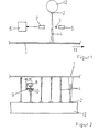
- a felt 1 for conditioning is a cross-machine direction 11 extending spray tube 12 assigned.
- the felt 1 is around an endlessly rotating press felt of a press nip of a press section Drainage of the fibrous web.
- the spray tube 12 has spray nozzles directed at the felt 1 at regular intervals 2 for moistening the same. So that this not only in, but also across Machine direction 11, d. H. the tape running direction is as even as possible, the function of the spray nozzles 2 must be monitored.
- repair measures can be taken immediately be initiated so that the impact on the manufacturing process of the Stay fibrous web minimal.
- FIG. 2 shows a traversing measuring arrangement.
- the function of the spray nozzles 2 is not constant, but time-cyclical detected.
- the pressure exerted by the spray jet 4 on a pressure gauge 8 is measured, for which purpose the pressure gauge 8 is moved between felt 1 and spray nozzle 2.
- the Pressure is proportional to the flow impulse, so its reduction from Normal means a malfunction of the spray nozzle 2.
- spray jets 4 become more normal Extension all the way to the pressure gauge 8. This is achieved through an aperture 9 with a measuring opening 10 to limit the part to be detected of the spray jet 4, which is arranged between the spray nozzle 2 and the pressure gauge 8 is. If the spray jet 4 is widened due to a nozzle fault, the bounces outer part of the spray jet 4 from the aperture 9. As a result, with disturbed spray jets 4 only a part of the respective spray jet 4 reaches the pressure gauge 8 the sensitivity to the detection of faults.
- the flow pulse should be detected by evaluating the rotation of an impeller are, the impeller is partially driven into the spray jet 4 for this purpose.
Landscapes
- Chemical & Material Sciences (AREA)
- Analytical Chemistry (AREA)
- Paper (AREA)
- Treatment Of Fiber Materials (AREA)
Abstract
Description
Claims (13)
- Verfahren zur Überwachung der Funktion von Spritzdüsenanordnungen in Maschinen zur Herstellung und/oder Veredelung von Papier-, Karton-, Tissue- oder anderen Faserstoffbahnen, wobei die Spritzdüsen (2) zumindest in einer Reihe quer zur Maschinenlaufrichtung (11) nebeneinander angeordnet sind, dadurch gekennzeichnet, dass
die Funktion der Spritzdüsen (2) über die Beeinflussung eines Lichtstrahls (3) durch den Spritzstrahl (4) erfasst wird. - Verfahren nach Anspruch 1, dadurch gekennzeichnet, dass
der vom Spritzstrahl (4) reflektierte Teil des Lichtstrahls (3) gemessen wird. - Verfahren nach'Anspruch 1 oder 2, dadurch gekennzeichnet, dass
der durch den Spritzstrahl (4) gelangende Teil des Lichtstrahls (3) gemessen wird. - Verfahren zur Überwachung der Funktion von Spritzdüsenanordnungen in Maschinen zur Herstellung und/oder Veredelung von Papier-, Karton-, Tissue- oder anderen Faserstoffbahnen, wobei die Spritzdüsen (2) zumindest in einer Reihe quer zur Maschinenlaufrichtung (11) nebeneinander angeordnet sind, dadurch gekennzeichnet, dass
die Funktion der Spritzdüsen (2) über die Messung des Strömungsimpulses des Spritzstrahls (4) der jeweiligen Spritzdüse (2) erfasst wird. - Vorrichtung zur Durchführung des Verfahrens nach einem der Ansprüche 1 bis
3, dadurch gekennzeichnet, dass
dem zu überwachenden Spritzstrahl (4) eine Messanordnung bestehend aus einem Lichtsender (5) und einem, mit einer Steuereinheit (6) verbundenen Lichtempfänger (7) zugeordnet ist. - Vorrichtung nach Anspruch 5, dadurch gekennzeichnet, dass
jedem Spritzstrahl (4) eine Messanordnung zugeordnet ist. - Vorrichtung nach Anspruch 5, dadurch gekennzeichnet, dass
die Messanordnung entlang mehrerer Spritzstrahlen (4) traversierbar gestaltet ist. - Vorrichtung zur Durchführung des Verfahrens nach Anspruch 4, dadurch gekennzeichnet, dass
eine Messanordnung von einem, mit einer Steuereinheit verbundenen Strömungsimpulsmesser gebildet wird und entlang mehrerer Spritzstrahlen (4) traversierbar gestaltet ist. - Vorrichtung nach Anspruch 8, dadurch gekennzeichnet, dass
die Messanordnung entlang aller Spritzstrahlen (4) traversierbar gestaltet ist. - Vorrichtung nach Anspruch 8 oder 9, dadurch gekennzeichnet, dass
der Strömungsimpuls des jeweiligen Spritzstrahls (4) von einem Drehzahlmesser gemessen wird, welcher mit einem, in den Spritzstrahl (4) gebrachten Flügelrad gekoppelt ist. - Vorrichtung nach Anspruch 8 oder 9, dadurch gekennzeichnet, dass
der Strömungsimpuls von einem, in den Spritzstrahl (4) gebrachten Druckmesser (8) gemessen wird. - Vorrichtung nach Anspruch 11, dadurch gekennzeichnet, dass
zwischen Druckmesser (8) und Spritzdüse (2) eine Blende (9) mit einer Messöffnung (10) zur Begrenzung des zu erfassenden Teils des Spritzstrahls (4) angeordnet ist. - Anwendung des Verfahrens sowie der Vorrichtung nach einem der vorhergehenden Ansprüche bei einem quer zur Maschinenlaufrichtung (11) verlaufenden Spritzrohr (12) mit mehreren, nebeneinander angeordneten Spritzdüsen (2) zur Konditionierung von Sieben, Filzen (1) und Bändern mit Reinigungsflüssigkeit, insbesondere Wasser.
Applications Claiming Priority (2)
| Application Number | Priority Date | Filing Date | Title |
|---|---|---|---|
| DE10116666A DE10116666A1 (de) | 2001-04-04 | 2001-04-04 | Spritzdüsen |
| DE10116666 | 2001-04-04 |
Publications (2)
| Publication Number | Publication Date |
|---|---|
| EP1247896A2 true EP1247896A2 (de) | 2002-10-09 |
| EP1247896A3 EP1247896A3 (de) | 2004-01-02 |
Family
ID=7680276
Family Applications (1)
| Application Number | Title | Priority Date | Filing Date |
|---|---|---|---|
| EP02002826A Withdrawn EP1247896A3 (de) | 2001-04-04 | 2002-02-08 | Verfahren und Vorrichtung zur Überwachung der Funktion von Spritzdüsen |
Country Status (2)
| Country | Link |
|---|---|
| EP (1) | EP1247896A3 (de) |
| DE (1) | DE10116666A1 (de) |
Cited By (2)
| Publication number | Priority date | Publication date | Assignee | Title |
|---|---|---|---|---|
| GB2507069A (en) * | 2012-10-17 | 2014-04-23 | Siemens Plc | Monitoring the quality of an electrostatic coating by measuring light reflected from a spray |
| EP2799830A4 (de) * | 2011-12-28 | 2015-08-26 | Posco | Sensorvorrichtung und vorrichtung zur beurteilung der leistung eines kühlsystems damit |
Family Cites Families (8)
| Publication number | Priority date | Publication date | Assignee | Title |
|---|---|---|---|---|
| DE444495C (de) * | 1927-08-09 | Heinrich Schaaf | Um ihre Laengsachse drehbare Spritzvorrichtung zum Reinigen der Siebe und Filze, zumFeuchten des Papiers und aehnlicher Stoffe in Papier- und aehnlichen Maschinen | |
| JPS6295161A (ja) * | 1985-10-18 | 1987-05-01 | Toyo Seikan Kaisha Ltd | スプレイモニタ装置 |
| JPH0771688B2 (ja) * | 1991-03-27 | 1995-08-02 | 株式会社神戸製鋼所 | 水冷用ノズルの詰まり検出方法 |
| US5312039A (en) * | 1992-06-22 | 1994-05-17 | Vlsi Technology, Inc. | Electro-optic monitor for fluid spray pattern |
| DE4447378A1 (de) * | 1994-12-22 | 1996-06-27 | Optronik Gmbh Opto Elektronisc | Anordnung zur Erkennung von Inhomogenitäten beim Dosieren von fließfähigen Stoffen |
| JP3520634B2 (ja) * | 1995-11-13 | 2004-04-19 | 日産自動車株式会社 | 液体噴射ノズルの目詰まり検出装置 |
| DE19543869A1 (de) * | 1995-11-24 | 1997-05-28 | Seidenader Maschinenbau Gmbh | Verfahren und Vorrichtung zur kontinuierlichen Überwachung der Flüssigkeitszugabe |
| US6065203A (en) * | 1998-04-03 | 2000-05-23 | Advanced Energy Systems, Inc. | Method of manufacturing very small diameter deep passages |
-
2001
- 2001-04-04 DE DE10116666A patent/DE10116666A1/de not_active Withdrawn
-
2002
- 2002-02-08 EP EP02002826A patent/EP1247896A3/de not_active Withdrawn
Cited By (2)
| Publication number | Priority date | Publication date | Assignee | Title |
|---|---|---|---|---|
| EP2799830A4 (de) * | 2011-12-28 | 2015-08-26 | Posco | Sensorvorrichtung und vorrichtung zur beurteilung der leistung eines kühlsystems damit |
| GB2507069A (en) * | 2012-10-17 | 2014-04-23 | Siemens Plc | Monitoring the quality of an electrostatic coating by measuring light reflected from a spray |
Also Published As
| Publication number | Publication date |
|---|---|
| EP1247896A3 (de) | 2004-01-02 |
| DE10116666A1 (de) | 2002-10-10 |
Similar Documents
| Publication | Publication Date | Title |
|---|---|---|
| DE69710356T2 (de) | Verfahren und vorrichtung zur erkennung von löcher und verstopften stellen | |
| DE4311402A1 (de) | Meßvorrichtung zum Messen des Zustands eines Papiermaschinenfilzes | |
| CH659494A5 (de) | Verfahren und vorrichtung zur analyse von garnunregelmaessigkeiten. | |
| EP1516954B1 (de) | Vorrichtung zur Beurteilung der Beschaffenheit mindestens eines umlaufenden Bandes | |
| DE3539354A1 (de) | Verfahren und vorrichtung zum lokalisieren von funktionsstoerungen an den maschinenelementen einer papiermaschine | |
| DE4419540C2 (de) | Verfahren und Vorrichtung zur Reinigung einer umlaufenden Sieb- oder Filzbahn | |
| DE19632988C1 (de) | Verfahren zur Beseitigung von Papierfehlern bei der kontinuierlichen Papierherstellung | |
| EP0868305B1 (de) | Vorrichtung und verfahren zur überwachung der sprühmenge einer zur befeuchtung bewegter materialbahnen in die breite versprühten flüssigkeit | |
| DE3827752A1 (de) | Verfahren und vorrichtung zur erfassung der oberflaeche von schleifscheiben | |
| DE69621305T2 (de) | Verfahren und Vorrichtung zur Messung der Luftdurchlässigkeit in Trockenfilz | |
| EP1247896A2 (de) | Verfahren und Vorrichtung zur Überwachung der Funktion von Spritzdüsen | |
| EP1521075A2 (de) | Vorrichtung und Verfahren zur Bestimmung der Permeabilität eines umlaufenden Bandes | |
| WO2012130694A2 (de) | Vorrichtung und verfahren zum reinigen und/oder konditionieren einer bespannung | |
| DE102020204686A1 (de) | Vorrichtungseinheit zur Bestimmung einer Durchflussmenge einer Düse | |
| EP1236024B1 (de) | Verfahren und vorrichtung zur durchflussmessung von gasen und flüssigkeiten | |
| EP1707670B1 (de) | Reinigungsverfahren | |
| EP2145693A1 (de) | Überwachung eines Auftragsmedienstromes beim Auftrag auf eine Papier-, Karton- oder andere Faserstoffbahn | |
| DE4017293C1 (en) | High pressure fluid cleaning method - involves using equation with deviation detected to selectively halt operation | |
| DE102022004683B4 (de) | Verfahren und Vorrichtung zur Erfassung der Permeabilität von Siebbändern | |
| EP1524363B1 (de) | Verfahren und Anordnung zur Bestimmung der Wasserdurchlässigkeit einer Bespannung | |
| DE102004051926A1 (de) | Filterherstellungsverfahren sowie -vorrichtung | |
| WO1996026412A1 (de) | Gleitplatte | |
| EP1856318B1 (de) | Vorrichtung und verfahren zur reinigung und überprüfung der löcher eines düsenstreifens | |
| DE102014019336B3 (de) | Vorrichtung zum Schutz der Fenster von Laserabstandssensoren | |
| WO2011076454A1 (de) | Verfahren und vorrichtung zur erkennung von oberflächendefekten an walzen |
Legal Events
| Date | Code | Title | Description |
|---|---|---|---|
| PUAI | Public reference made under article 153(3) epc to a published international application that has entered the european phase |
Free format text: ORIGINAL CODE: 0009012 |
|
| AK | Designated contracting states |
Kind code of ref document: A2 Designated state(s): AT BE CH CY DE DK ES FI FR GB GR IE IT LI LU MC NL PT SE TR |
|
| AX | Request for extension of the european patent |
Free format text: AL;LT;LV;MK;RO;SI |
|
| PUAL | Search report despatched |
Free format text: ORIGINAL CODE: 0009013 |
|
| RIC1 | Information provided on ipc code assigned before grant |
Ipc: 7B 05B 12/08 B Ipc: 7D 21F 1/32 B Ipc: 7D 21F 1/34 B Ipc: 7D 21G 7/00 A |
|
| AK | Designated contracting states |
Kind code of ref document: A3 Designated state(s): AT BE CH CY DE DK ES FI FR GB GR IE IT LI LU MC NL PT SE TR |
|
| AX | Request for extension of the european patent |
Extension state: AL LT LV MK RO SI |
|
| 17P | Request for examination filed |
Effective date: 20040702 |
|
| AKX | Designation fees paid |
Designated state(s): AT DE FI IT SE |
|
| RAP1 | Party data changed (applicant data changed or rights of an application transferred) |
Owner name: VOITH PATENT GMBH |
|
| STAA | Information on the status of an ep patent application or granted ep patent |
Free format text: STATUS: THE APPLICATION IS DEEMED TO BE WITHDRAWN |
|
| 18D | Application deemed to be withdrawn |
Effective date: 20060524 |