EP1249948A1 - Méthode et appareil pour la maximalisation du débit de données via l'allocation variable des préambules dans un réseau de radiocommunication - Google Patents
Méthode et appareil pour la maximalisation du débit de données via l'allocation variable des préambules dans un réseau de radiocommunication Download PDFInfo
- Publication number
- EP1249948A1 EP1249948A1 EP02252160A EP02252160A EP1249948A1 EP 1249948 A1 EP1249948 A1 EP 1249948A1 EP 02252160 A EP02252160 A EP 02252160A EP 02252160 A EP02252160 A EP 02252160A EP 1249948 A1 EP1249948 A1 EP 1249948A1
- Authority
- EP
- European Patent Office
- Prior art keywords
- signal
- channel response
- output frequency
- preamble
- radio
- Prior art date
- Legal status (The legal status is an assumption and is not a legal conclusion. Google has not performed a legal analysis and makes no representation as to the accuracy of the status listed.)
- Withdrawn
Links
- 238000004891 communication Methods 0.000 title claims abstract description 19
- 238000000034 method Methods 0.000 title claims description 21
- 230000005540 biological transmission Effects 0.000 claims abstract description 37
- 230000002123 temporal effect Effects 0.000 claims abstract description 24
- 238000005259 measurement Methods 0.000 claims abstract description 22
- 238000010586 diagram Methods 0.000 description 7
- 238000003780 insertion Methods 0.000 description 4
- 230000037431 insertion Effects 0.000 description 4
- 238000012937 correction Methods 0.000 description 3
- 230000003247 decreasing effect Effects 0.000 description 2
- 230000008054 signal transmission Effects 0.000 description 2
- 230000007423 decrease Effects 0.000 description 1
- 238000012966 insertion method Methods 0.000 description 1
- 238000000691 measurement method Methods 0.000 description 1
- 230000001360 synchronised effect Effects 0.000 description 1
Images


Classifications
-
- H—ELECTRICITY
- H04—ELECTRIC COMMUNICATION TECHNIQUE
- H04L—TRANSMISSION OF DIGITAL INFORMATION, e.g. TELEGRAPHIC COMMUNICATION
- H04L25/00—Baseband systems
- H04L25/02—Details ; arrangements for supplying electrical power along data transmission lines
- H04L25/0202—Channel estimation
- H04L25/0224—Channel estimation using sounding signals
- H04L25/0226—Channel estimation using sounding signals sounding signals per se
Definitions
- the present invention relates to a radio communication apparatus, system and method for transmitting a radio signal in accordance with a transmission format in which a channel response calculation preamble signal serving as a reference is inserted.
- a receiver calculates the channel response of the channel response calculation preamble signal.
- the channel response indicates the degree of distortion of phase, amplitude, or the like.
- the receiver multiplies the received data signal by the inverse characteristic of the channel response to compensate the received data signal for any distortion.
- an insertion method of the channel response calculation preamble signal is fixed in a system.
- This method includes a method of inserting a channel response calculation preamble signal at given time intervals, a method of inserting at the head of a packet or frame sent toward a given user, and the like.
- the channel response calculation result obtained from the channel response calculation preamble signal has a large error from the channel distortion which is actually superposed on the data.
- an object of the present invention to provide a radio communication apparatus, system and method, which can accurately calculate a channel response and can reduce any transmission error even when the channel variation is large.
- a radio communication method for transmitting a transmitted signal including a preamble signal used for calculating a channel response at a receiving side comprises setting an output frequency of the preamble signal based on a temporal change of a radio propagation environment; and generating the transmitted signal by inserting the preamble signal in accordance with the output frequency.
- the frequency of output of the channel response calculation preamble signal can be increased, and distortion correction that traces the channel variation along with an elapse of time can be made.
- the frequency of output of the channel response calculation preamble signal can be decreased, and the data transmission efficiency can be improved.
- FIG. 1 shows an example of the transmitted signal format of a radio communication system according to the present invention.
- a transmitted signal is made up of a synchronization preamble signal, at least one channel response calculation preamble signal (k signals in FIG. 1), and a plurality of data.
- the number of channel response calculation preamble signals is variable in accordance with a channel variation.
- the transmitting side controls the frequency of the channel response calculation preamble signal in accordance with the channel variation.
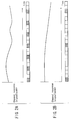
- FIGS. 2A and 2B are examples of graphs showing temporal variations of power as a channel response.
- the abscissa shows time, and the ordinate shows the intra-band average power of the channel response.
- FIG. 2A shows a temporal variation of power when the temporal variation of channel response is large
- FIG. 2B shows a temporal variation of power when the temporal variation of channel response is small.
- FIG. 2A An appropriate channel format corresponding to the temporal variation of power of the channel response is shown below each graph that shows the temporal variation of power of the channel response.
- FIG. 2A when the temporal variation of channel response is large, the frequency of insertion of channel response calculation preamble signal is increased. A channel response to be calculated to compensate for a data distortion can be updated in correspondence with the temporal variation of channel response. Therefore, a transmission error can be reduced. That is, when the temporal variation of channel response is large, a data length m between two channel response calculation preamble signals is set to be a small value, thus reducing transmission errors.
- the number of channel response calculation preamble signals inserted is varied in accordance with the temporal variation of channel response.
- FIG. 3 shows an example of the transmitted signal format in a radio communication system and radio transmission apparatus according to an embodiment of the present invention
- FIGS. 4, 5, and 6 are block diagrams.
- a control signal field written with control information which is used to demodulate data, is added to the transmitted signal format shown in FIG. 1. Since this control signal field is included, the receiving side can normally demodulate data by recognizing control information written in the control signal field.
- control signal field is inserted immediately after the first channel response calculation preamble signal, but its insertion position is not particularly limited.
- the control signal field contains a channel response calculation preamble signal output frequency field.
- the transmitting side writes transmission frequency information of channel response calculation preamble signals in the channel response calculation preamble signal output frequency field.
- the receiving side can detect the transmission frequency of channel response calculation preamble signals set at the transmitting side with reference to the contents of the channel response calculation preamble signal output frequency field, and can calculate a channel response at a correct timing.
- the receiving side can detect the output frequency, it can detect the position of the next channel response calculation preamble signal.
- the output frequency indicates that channel response calculation preamble signals are inserted every n symbols, for example.
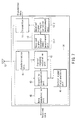
- FIG. 4 shows an example of a radio transmission apparatus according to the present invention.
- a base station 1 and terminal 2 have radio transmission apparatuses with the same arrangement.
- a transmitter 11 of the base station 1 transmits a transmitted signal which contains transmitted data and channel response calculation preamble signals in the transmission format shown in FIG. 3 from an antenna 12. Note that an optimal number of channel response calculation preamble signals is set in accordance with channel variation information output from a channel variation measurement unit 13.
- the terminal 2 receives the transmitted signal transmitted from the base station 1 by an antenna 22, and this signal is input to a receiver 24.
- the receiver 24 executes a reception process such as transmission distortion compensation and the like of a received signal using channel response calculation preamble signals, and outputs received data. Also, the receiver 24 outputs information used to measure a variation of channel response to a channel response variation measurement unit 23. As an input signal to the channel response variation measurement unit 23, a channel response calculation result or the like of the received signal is used.
- the channel response variation measurement unit 23 measures a variation of channel response, and outputs the measurement result to a transmitter 21.
- the measurement method of the variation of channel response includes:
- the transmitter 21 executes the same process as the transmission process of the base station 1, and outputs a transmitted signal to the base station 1 again. In this manner, a signal is transmitted between the base station 1 and terminal 2.
- FIG. 5 is a block diagram for explaining the transmitter 11 of the radio transmission apparatus shown in FIG. 4. Since the radio transmission apparatuses of the base station 1 and terminal 2 have the same arrangement, the transmitter 11 of the base station 1 will be explained as an example.
- the signal which is received by the antenna 12 and has the transmission format shown in FIG. 3 is input to a receiver 14.
- the receiver 14 executes a reception process of the received signal (to be described later), and outputs information used to measure a variation of channel response to a channel response variation measurement unit 13.
- a channel response variation measurement unit 13 As an input signal to the channel response variation measurement unit 13, for example, a channel response calculation result or the like is used.
- the channel response variation measurement unit 13 measures a variation of channel response, and outputs the measurement result to a channel response calculation preamble signal output frequency setting unit 31.
- the channel response calculation preamble signal output frequency setting unit 31 determines an optimal output frequency of channel response calculation preamble signals using the measurement result of the channel response variation, and informs a transmitted signal generator 32 and control signal field generator 33 of the output frequency of channel response calculation preamble signals.
- the control signal field generator 33 writes information of the channel response calculation preamble signal output frequency in the control signal field.
- transmitted data is converted into a data signal by a data signal generator 34, and the data signal, a synchronization preamble signal and channel response calculation preamble signals generated by a preamble signal generator 35, and the control signal field generated by the control signal field generator 33 are input to the transmitted signal generator 32.
- the transmitted signal generator 32 generates a transmitted signal based on the transmitted signal format shown in FIG. 3, and outputs it from the antenna 12.
- the channel response calculation preamble signals are inserted at the frequency set by the channel response calculation preamble signal output frequency setting unit 31. In this manner, the output frequency of channel response calculation preamble signals can be changed in accordance with a variation of channel response.
- FIG. 6 is a block diagram for explaining the receiver 14 of the radio transmission apparatus of the base station 1 shown in FIG. 4.
- the signal which is received by the antenna 12 and has the transmission format shown in FIG. 3 is input to a synchronization unit 41.
- the synchronization unit 41 synchronizes the received signal, and outputs the synchronized received signal to a channel response calculation unit 42 and distortion compensation unit 43.
- the channel response calculation preamble signal is input to the channel response calculation unit 42, and other signals are input to the distortion compensation unit 43.
- the channel response calculated by the channel response calculation unit 42 is input to the distortion compensation unit 43.
- the distortion compensation unit 43 compensates the received signal for any distortion using the channel response calculated by the channel response calculation unit 42.
- the control signal field is input to a control signal field analysis unit 44, which reads out control information required to demodulate, and supplies it to a data demodulation unit 45.
- the data demodulation unit 45 demodulates the distortion-compensated signal, and outputs the demodulated signal as received data.
- control signal field analysis unit 44 reads out information indicating the channel response calculation preamble signal output frequency, and informs the distortion compensation unit 43 and channel response calculation unit 42 of that channel response calculation preamble signal output frequency.
- the channel response calculation unit 42 supplies a channel response calculation preamble signal to the channel variation measurement unit 13, which measures the variation of channel response.
- the frequency of channel response calculation preamble signals to be inserted in the transmitted signal format by the transmitter 11 is changed in accordance with the measurement result.
- the frequency of channel response calculation preamble signals to be inserted in the signal format to be transmitted is changed in accordance with the channel variation, the channel response can be accurately calculated even when the channel variation is large, and a transmission error can be reduced.
- the channel response calculation preamble signal output frequency is sent to the distortion compensation unit 43 and channel response calculation unit 42, a channel response can be calculated at an accurate timing, and accurate distortion compensation can be made.
- the channel response calculation unit 42 can correctly recognize the reception timing of a channel response calculation preamble signal based on the received channel response calculation preamble signal output frequency information, and can calculate a channel response at a correct timing.
- the distortion correction unit 43 can correctly recognize the distortion compensation timing of data or the control signal field based on the received channel response calculation preamble signal output frequency.
- the distortion-compensated data is input to and demodulated by the demodulation unit 45. In this way, since the receiving side accurately recognizes the channel response calculation preamble signal output frequency, the data and control signal field can undergo distortion correction at correct timings. For this reason, even when the transmitting side varies the channel response calculation preamble signal output frequency, the data signal can be correctly demodulated.
- the transmitted signal format shown in FIG. 3 contains the channel response calculation preamble signal output frequency field used to inform, from the transmitting side, the receiving side of the channel response calculation preamble signal transmission frequency.
- information indicating the channel response calculation preamble signal output frequency may be contained in data.
- the channel response calculation preamble signal output frequency information is written in the transmitted signal.
- no channel response calculation preamble signal output frequency information may be written in the transmitted signal.
- the control signal field generator 33 of the transmitter, and the control signal analysis unit 44 of the receiver may be omitted.
- a method of calculating a correlation between each symbol and a channel response calculation preamble signal on the receiving side, and determining a symbol with high correlation as a channel response calculation preamble signal may be used.
- received signal strength (RSSI) information of a received signal may be used. Using the RSSI, a variation of channel response is measured.
- the channel response variation measurement unit 13 comprises a received signal strength measurement unit 13-1 and received signal strength variation measurement unit 13-2.
- the received signal strength measurement unit 13-1 measures the received signal strength of a received signal from the antenna 12, and the received signal strength variation measurement unit 13-2 measures a variation of received signal strength.
- the result of the received signal strength variation measurement unit 13-2 is input to the channel response calculation preamble signal output frequency setting unit 31 of the transmitter 11, thus setting the channel response calculation preamble signal output frequency in correspondence with the channel variation.
- the channel response calculation preamble signal output frequency is set inside the transmitter of the radio transmission apparatus that generates a transmitted signal.
- some radio transmission system may receive channel response calculation preamble signal output frequency information from a communication partner.
- the channel response variation measurement unit 13 and channel response calculation preamble frequency setting unit 31 may be omitted.
- Channel response calculation preamble signals may be inserted into the transmission format of a transmitted signal based on the channel response calculation preamble signal transmission frequency provided from the communication partner.
Landscapes
- Engineering & Computer Science (AREA)
- Power Engineering (AREA)
- Computer Networks & Wireless Communication (AREA)
- Signal Processing (AREA)
- Mobile Radio Communication Systems (AREA)
- Synchronisation In Digital Transmission Systems (AREA)
- Digital Transmission Methods That Use Modulated Carrier Waves (AREA)
- Cable Transmission Systems, Equalization Of Radio And Reduction Of Echo (AREA)
Applications Claiming Priority (2)
| Application Number | Priority Date | Filing Date | Title |
|---|---|---|---|
| JP2001087040 | 2001-03-26 | ||
| JP2001087040A JP3583730B2 (ja) | 2001-03-26 | 2001-03-26 | 無線通信システム及び無線伝送装置 |
Publications (1)
| Publication Number | Publication Date |
|---|---|
| EP1249948A1 true EP1249948A1 (fr) | 2002-10-16 |
Family
ID=18942335
Family Applications (1)
| Application Number | Title | Priority Date | Filing Date |
|---|---|---|---|
| EP02252160A Withdrawn EP1249948A1 (fr) | 2001-03-26 | 2002-03-26 | Méthode et appareil pour la maximalisation du débit de données via l'allocation variable des préambules dans un réseau de radiocommunication |
Country Status (3)
| Country | Link |
|---|---|
| US (2) | US7403545B2 (fr) |
| EP (1) | EP1249948A1 (fr) |
| JP (1) | JP3583730B2 (fr) |
Families Citing this family (10)
| Publication number | Priority date | Publication date | Assignee | Title |
|---|---|---|---|---|
| JP4050595B2 (ja) * | 2002-11-11 | 2008-02-20 | 松下電器産業株式会社 | 無線通信システム及び無線通信方法並びに無線通信装置 |
| JP4407126B2 (ja) * | 2003-01-09 | 2010-02-03 | ソニー株式会社 | 無線通信システム、無線通信装置及び無線通信方法、並びにコンピュータ・プログラム |
| JP2005020076A (ja) * | 2003-06-23 | 2005-01-20 | Toshiba Corp | 通信方法、送信装置および受信装置 |
| US7400643B2 (en) * | 2004-02-13 | 2008-07-15 | Broadcom Corporation | Transmission of wide bandwidth signals in a network having legacy devices |
| JP2007288656A (ja) * | 2006-04-19 | 2007-11-01 | Toyota Infotechnology Center Co Ltd | 無線通信装置、無線通信方法、および無線通信プログラム |
| JP4998169B2 (ja) * | 2007-09-20 | 2012-08-15 | 富士通株式会社 | 無線通信装置および伝搬環境指標分散抑制方法 |
| US9049065B2 (en) | 2009-05-11 | 2015-06-02 | Qualcomm Incorporated | Removal of ICI/ISI errors in frequency domain channel estimation for wireless repeaters |
| US20110116531A1 (en) * | 2009-05-11 | 2011-05-19 | Qualcomm Incorporated | Removal of multiplicative errors in frequency domain channel estimation for wireless repeaters |
| US20100284447A1 (en) * | 2009-05-11 | 2010-11-11 | Qualcomm Incorporated | Frequency domain feedback channel estimation for an interference cancellation repeater including sampling of non causal taps |
| JP6740718B2 (ja) * | 2016-05-31 | 2020-08-19 | ソニー株式会社 | 無線装置、および制御方法 |
Citations (3)
| Publication number | Priority date | Publication date | Assignee | Title |
|---|---|---|---|---|
| US5566172A (en) * | 1992-12-30 | 1996-10-15 | Alcatel N.V. | Method for transmitting information at high speed by multiple burst allocation and associated receiving method and device |
| EP0903872A1 (fr) * | 1997-09-17 | 1999-03-24 | Motorola, Inc. | Système de communication radio ayant un format de trame de transmission et procédé pour sa réalisation |
| GB2329796A (en) * | 1997-09-29 | 1999-03-31 | Motorola Ltd | Increased data rate by reduction of training data |
Family Cites Families (41)
| Publication number | Priority date | Publication date | Assignee | Title |
|---|---|---|---|---|
| US3701023A (en) * | 1971-06-29 | 1972-10-24 | Ibm | Phase jitter extraction method for data transmission systems |
| US3715670A (en) * | 1971-12-20 | 1973-02-06 | Bell Telephone Labor Inc | Adaptive dc restoration in single-sideband data systems |
| US4002991A (en) * | 1975-01-29 | 1977-01-11 | Nippon Gakki Seizo Kabushiki Kaisha | Pilot signal extracting circuitry |
| US4706244A (en) * | 1985-01-15 | 1987-11-10 | Rockwell International Corporation | Frequency multiplexed telephone system |
| JP2715057B2 (ja) * | 1994-04-05 | 1998-02-16 | クウォンタム・コーポレイション | データ記憶装置においてアンダーシュート誘起タイミング位相ステップを排除する方法およびハードディスクドライブ |
| US5636252A (en) * | 1994-05-04 | 1997-06-03 | Samsung Electronics Co., Ltd. | Automatic gain control of radio receiver for receiving digital high-definition television signals |
| US5953370A (en) * | 1994-09-09 | 1999-09-14 | Omnipoint Corporation | Apparatus for receiving and correlating a spread spectrum signal |
| US5602833A (en) * | 1994-12-19 | 1997-02-11 | Qualcomm Incorporated | Method and apparatus for using Walsh shift keying in a spread spectrum communication system |
| JP3242287B2 (ja) * | 1995-04-27 | 2001-12-25 | 株式会社日立製作所 | 無線通信システムおよび通信装置 |
| US5781540A (en) * | 1995-06-30 | 1998-07-14 | Hughes Electronics | Device and method for communicating in a mobile satellite system |
| US6307868B1 (en) * | 1995-08-25 | 2001-10-23 | Terayon Communication Systems, Inc. | Apparatus and method for SCDMA digital data transmission using orthogonal codes and a head end modem with no tracking loops |
| US6356555B1 (en) * | 1995-08-25 | 2002-03-12 | Terayon Communications Systems, Inc. | Apparatus and method for digital data transmission using orthogonal codes |
| JP2000508128A (ja) * | 1995-10-24 | 2000-06-27 | ジェネラル・インスツルメント・コーポレイション | マルチレイヤー送信フォーマットの物理的レイヤーを通じた可変長バースト送信 |
| US6181497B1 (en) * | 1995-12-12 | 2001-01-30 | International Business Machines Corporation | System and method for providing nonadjacent redundancy synchronization bytes |
| US6359938B1 (en) * | 1996-10-31 | 2002-03-19 | Discovision Associates | Single chip VLSI implementation of a digital receiver employing orthogonal frequency division multiplexing |
| JP3575215B2 (ja) * | 1997-03-05 | 2004-10-13 | 株式会社日立製作所 | パケット通信方法及び通信端末装置 |
| US6259709B1 (en) * | 1997-05-02 | 2001-07-10 | Legerity, Inc. | Training preamble added to CT2 muxes in a CT2 wireless telecommunications system |
| US20020131393A1 (en) * | 1997-08-12 | 2002-09-19 | Andrew Baldridge | Graphic user interface for a radio location determination system |
| US6307840B1 (en) * | 1997-09-19 | 2001-10-23 | Qualcomm Incorporated | Mobile station assisted timing synchronization in CDMA communication system |
| US6144691A (en) * | 1997-09-30 | 2000-11-07 | Nokia Mobile Phones Limited | Method and apparatus for synchronizing to a direct sequence spread spectrum signal |
| US6370158B1 (en) * | 1997-11-14 | 2002-04-09 | Wireless Facilities, Inc. | Wireless T/E Transceiver frame signaling subcontroller |
| US6356598B1 (en) * | 1998-08-26 | 2002-03-12 | Thomson Licensing S.A. | Demodulator for an HDTV receiver |
| US6243369B1 (en) * | 1998-05-06 | 2001-06-05 | Terayon Communication Systems, Inc. | Apparatus and method for synchronizing an SCDMA upstream or any other type upstream to an MCNS downstream or any other type downstream with a different clock rate than the upstream |
| US6618452B1 (en) * | 1998-06-08 | 2003-09-09 | Telefonaktiebolaget Lm Ericsson (Publ) | Burst carrier frequency synchronization and iterative frequency-domain frame synchronization for OFDM |
| US6219377B1 (en) * | 1998-06-29 | 2001-04-17 | Legerity, Inc. | Method and apparatus for generating tones in a multi-tone modem |
| PT1101294E (pt) * | 1998-07-28 | 2011-03-15 | Samsung Electronics Co Ltd | Transmissão descontínua num estado de manutenção do canal de controlo num sistema de comunicações cdma |
| US6252865B1 (en) * | 1998-10-02 | 2001-06-26 | Qualcomm, Inc. | Methods and apparatuses for fast power control of signals transmitted on a multiple access channel |
| US6246431B1 (en) * | 1999-01-26 | 2001-06-12 | Zenith Electronics Corporation | Digital television system for reducing co-channel interference in 8 MHZ channels |
| EP1159846A1 (fr) * | 1999-03-08 | 2001-12-05 | Nokia Corporation | Procede permettant d'etablir une communication entre un appareil utilisateur et un reseau radio |
| US6606341B1 (en) * | 1999-03-22 | 2003-08-12 | Golden Bridge Technology, Inc. | Common packet channel with firm handoff |
| US6169759B1 (en) * | 1999-03-22 | 2001-01-02 | Golden Bridge Technology | Common packet channel |
| US6426973B1 (en) * | 1999-04-29 | 2002-07-30 | The Board Of Trustees Of The University Of Illinois | Differential minimum mean squared error communication signal compensation method |
| EP2259530B1 (fr) * | 1999-07-28 | 2019-03-27 | Panasonic Intellectual Property Corporation of America | Appareil pour la transmission et pour la réception de données, ainsi que méthode pour la radiodiffusion numérique |
| US7027464B1 (en) * | 1999-07-30 | 2006-04-11 | Matsushita Electric Industrial Co., Ltd. | OFDM signal transmission scheme, and OFDM signal transmitter/receiver |
| WO2001061878A1 (fr) * | 2000-02-17 | 2001-08-23 | Samsung Electronics Co., Ltd. | Dispositif et procede d'assignation d'une voie commune de transmission par paquets dans un systeme de communication amcr |
| WO2001063870A1 (fr) * | 2000-02-22 | 2001-08-30 | Koninklijke Philips Electronics N.V. | Recepteur de porteuses multiples a estimateur de canaux |
| CN1172464C (zh) * | 2000-06-21 | 2004-10-20 | 三星电子株式会社 | 接入网/终端装置及数据控制信道发送/接收法和通信法 |
| US20020097780A1 (en) * | 2000-11-30 | 2002-07-25 | Odenwalder Joseph P. | Preamble generation |
| US7567781B2 (en) * | 2001-01-05 | 2009-07-28 | Qualcomm, Incorporated | Method and apparatus for power level adjustment in a wireless communication system |
| US7010065B2 (en) * | 2001-05-25 | 2006-03-07 | Hitachi Global Storage Technologies Netherlands B.V. | Method and apparatus for word synchronization with large coding distance and fault tolerance for PRML systems |
| EP1603134A1 (fr) * | 2004-05-31 | 2005-12-07 | STMicroelectronics S.r.l. | Procédé pour améliorer la fiabilité de données dans un système de disque dur |
-
2001
- 2001-03-26 JP JP2001087040A patent/JP3583730B2/ja not_active Expired - Fee Related
-
2002
- 2002-03-22 US US10/102,835 patent/US7403545B2/en not_active Expired - Fee Related
- 2002-03-26 EP EP02252160A patent/EP1249948A1/fr not_active Withdrawn
-
2008
- 2008-06-24 US US12/145,218 patent/US20090003494A1/en not_active Abandoned
Patent Citations (3)
| Publication number | Priority date | Publication date | Assignee | Title |
|---|---|---|---|---|
| US5566172A (en) * | 1992-12-30 | 1996-10-15 | Alcatel N.V. | Method for transmitting information at high speed by multiple burst allocation and associated receiving method and device |
| EP0903872A1 (fr) * | 1997-09-17 | 1999-03-24 | Motorola, Inc. | Système de communication radio ayant un format de trame de transmission et procédé pour sa réalisation |
| GB2329796A (en) * | 1997-09-29 | 1999-03-31 | Motorola Ltd | Increased data rate by reduction of training data |
Non-Patent Citations (1)
| Title |
|---|
| NANDA S ET AL: "ADAPTATION TECHNIQUES IN WIRELESS PACKET DATA SERVICES", IEEE COMMUNICATIONS MAGAZINE, IEEE SERVICE CENTER. PISCATAWAY, N.J, US, vol. 38, no. 1, January 2000 (2000-01-01), pages 54 - 64, XP000908338, ISSN: 0163-6804 * |
Also Published As
| Publication number | Publication date |
|---|---|
| US20090003494A1 (en) | 2009-01-01 |
| JP2002290295A (ja) | 2002-10-04 |
| JP3583730B2 (ja) | 2004-11-04 |
| US7403545B2 (en) | 2008-07-22 |
| US20020136189A1 (en) | 2002-09-26 |
Similar Documents
| Publication | Publication Date | Title |
|---|---|---|
| US20090003494A1 (en) | Radio communication system and apparatus | |
| US6788737B1 (en) | Communication terminal apparatus, base station apparatus and communication method | |
| CA2120714C (fr) | Methode et appareil pour evaluer la qualite de la reception dans un recepteur | |
| US7672221B2 (en) | Radio receiver and radio signal receiving method | |
| EP1164733B1 (fr) | Procede de construction de canaux et station de base utilisant le procede | |
| US7321563B2 (en) | Apparatus and method for estimating a channel condition of a forward link in a mobile communication system | |
| JPH10257013A (ja) | 受信装置 | |
| JP2001333123A (ja) | 通信端末装置及び復調方法 | |
| EP1885080B1 (fr) | Appareil et procédé pour la synchronisation d'un analyseur de signaux | |
| US20100020864A1 (en) | Pulse transmitting device, pulse receiving device, pulse communication system, and pulse communication method | |
| US7599401B2 (en) | Transmission device and transmission method | |
| GB0130687D0 (en) | Parameter estimation for adaptive antenna system | |
| JPH11275035A (ja) | 移動局通信装置、基地局通信装置及び無線通信システム | |
| CN100578962C (zh) | 天线选择的方法及选择接收天线的系统和装置 | |
| EP1197026A1 (fr) | Procede et appareil pour l'estimation de voie, a diversite d'emission | |
| JP2590441B2 (ja) | 干渉波検出方法 | |
| JP3357653B2 (ja) | 無線受信装置 | |
| EP1881634B1 (fr) | Communication adaptative pour réseaux sans fil | |
| JP2005159849A (ja) | 無線通信システム、基地局装置及び情報交換方法 | |
| KR100836152B1 (ko) | 이동통신단말기 및 그 채널 상태 측정 방법 | |
| JP2003115786A (ja) | ディジタル無線通信装置 | |
| CN116318315B (zh) | 一种点对多点网络通信的中继方法及系统 | |
| JP2002344366A (ja) | 等化装置及び等化方法 | |
| KR102721648B1 (ko) | 주파수 옵셋에 강인한 군사용 협대역 무선 통신 시스템 | |
| EP1133125A1 (fr) | Dispositif et procede d'emission |
Legal Events
| Date | Code | Title | Description |
|---|---|---|---|
| PUAI | Public reference made under article 153(3) epc to a published international application that has entered the european phase |
Free format text: ORIGINAL CODE: 0009012 |
|
| 17P | Request for examination filed |
Effective date: 20020417 |
|
| AK | Designated contracting states |
Kind code of ref document: A1 Designated state(s): AT BE CH CY DE DK ES FI FR GB GR IE IT LI LU MC NL PT SE TR |
|
| AX | Request for extension of the european patent |
Free format text: AL;LT;LV;MK;RO;SI |
|
| RTI1 | Title (correction) |
Free format text: METHOD AND APPARATUS FOR MAXIMISING THROUGHPUT VIA VARIABLE PREAMBLE ALLOCATION IN A RADIO COMMUNICATIONS NETWORK |
|
| 17Q | First examination report despatched |
Effective date: 20030410 |
|
| AKX | Designation fees paid |
Designated state(s): DE FR GB |
|
| STAA | Information on the status of an ep patent application or granted ep patent |
Free format text: STATUS: THE APPLICATION IS DEEMED TO BE WITHDRAWN |
|
| 18D | Application deemed to be withdrawn |
Effective date: 20040826 |