EP1251005A2 - Procédé et dispositif de contrôle des presses rotatives pendant des coupures de courant - Google Patents
Procédé et dispositif de contrôle des presses rotatives pendant des coupures de courant Download PDFInfo
- Publication number
- EP1251005A2 EP1251005A2 EP02251318A EP02251318A EP1251005A2 EP 1251005 A2 EP1251005 A2 EP 1251005A2 EP 02251318 A EP02251318 A EP 02251318A EP 02251318 A EP02251318 A EP 02251318A EP 1251005 A2 EP1251005 A2 EP 1251005A2
- Authority
- EP
- European Patent Office
- Prior art keywords
- section
- power failure
- printing material
- power
- printing
- Prior art date
- Legal status (The legal status is an assumption and is not a legal conclusion. Google has not performed a legal analysis and makes no representation as to the accuracy of the status listed.)
- Withdrawn
Links
Images

Classifications
-
- B—PERFORMING OPERATIONS; TRANSPORTING
- B41—PRINTING; LINING MACHINES; TYPEWRITERS; STAMPS
- B41F—PRINTING MACHINES OR PRESSES
- B41F33/00—Indicating, counting, warning, control or safety devices
- B41F33/04—Tripping devices or stop-motions
- B41F33/12—Tripping devices or stop-motions for starting or stopping the machine as a whole
-
- B—PERFORMING OPERATIONS; TRANSPORTING
- B41—PRINTING; LINING MACHINES; TYPEWRITERS; STAMPS
- B41F—PRINTING MACHINES OR PRESSES
- B41F13/00—Common details of rotary presses or machines
- B41F13/004—Electric or hydraulic features of drives
- B41F13/0045—Electric driving devices
-
- B—PERFORMING OPERATIONS; TRANSPORTING
- B41—PRINTING; LINING MACHINES; TYPEWRITERS; STAMPS
- B41P—INDEXING SCHEME RELATING TO PRINTING, LINING MACHINES, TYPEWRITERS, AND TO STAMPS
- B41P2213/00—Arrangements for actuating or driving printing presses; Auxiliary devices or processes
- B41P2213/70—Driving devices associated with particular installations or situations
- B41P2213/73—Driving devices for multicolour presses
- B41P2213/734—Driving devices for multicolour presses each printing unit being driven by its own electric motor, i.e. electric shaft
Definitions
- the present invention relates generally to a method and apparatus for controlling a rotary press in a power failure, and more specifically to a method and apparatus for controlling, in a power failure, a so-called shaftless rotary press that produces printing impressions on paper by separately driving printing sections and folding sections with independent drive units.
- the present invention may allow switching of the operation of a shaftless rotary press in which the components thereof are subjected to electrical synchronous control when power feeding is interrupted due to a failure of main power supply so that a traveling paper web can be braked with a constant braking force to prevent uneven tensions from being exerted on the paper web even when power feeding is discontinued due to a main power failure, thereby, in a breakage of the paper web, preventing the broken web from clinging around the rotary components.
- the constant braking force is larger than the braking force before the interruption of power feeding.
- the present invention makes it possible to resume the printing operation of the shaftless rotary press immediately after the power is restored.
- the present invention may accomplish the control, in a main power failure, of a rotary press that carries out printing operation by driving the printing section and the folding section with separate drive sources, pulling the printing material that is currently being braked in the paper feeding section, and bringing the blanket cylinder of the printing section into contact with the printing material; the control to cope with the power failure being accomplished in such a manner that the braking of the printing material in the paper feeding section is changed over to a braking mode with a constant braking force as soon as power feeding to the rotary press is interrupted in the main power failure, a power failure signal is output by detecting a voltage drop due to the power failure, the power supply is changed over to a battery power supply, the blanket cylinder is detached from the printing material with the battery power upon receipt of the power failure signal, and the printing material pulling mechanism in the folding section is decelerated and brought to an emergency halt within a given length of time also with the battery power upon receipt of the power failure signal.
- the present invention may accomplish the control, in a power failure, of a rotary press that carries out printing operation by driving the printing section and the folding section with separate drive sources, pulling the printing material that is currently being braked in the paper feeding section, and bringing the blanket cylinder of the printing section into contact with the printing material; the control to cope with the power failure being accomplished in such a manner that the braking of the printing material in the paper feeding section is changed over to a braking mode with a constant braking force that is greater than the braking force before the power failure as soon as power feeding to the rotary press is interrupted in the power failure, a power failure signal is output by detecting a voltage drop due to the power failure, the power supply is changed over to a battery power supply, the blanket cylinder is detached from the printing material with the battery power upon receipt of the power failure signal, and the printing material pulling mechanism in the folding section is decelerated and brought to an emergency halt within a given length of time interval also with the battery power upon receipt of the power failure signal.
- the present invention may accomplish the control, in a power failure, of a rotary press comprising separate drive sources in the printing section and the folding section thereof, a printing material braking mechanism for countering the pulling of the printing material in the paper feeding section thereof, a blanket cylinder moving mechanism for selectively moving the blanket cylinder in a direction away from the direction in which the blanket cylinder comes in contact with the printing material in the printing section thereof, and a printing material pulling mechanism for pulling the printing material by the rotation of a drag roller at least in the most upstream part of the folding section; the improvement comprising a printing material braking mechanism adapted to be changeable to a braking mode with a constant braking force as soon as power feeding to the rotary press is interrupted due to a main power failure, an uninterruptible power supply having a power failure signal output section with the power input side thereof connected to an external power supply for outputting a power failure signal by detecting a voltage drop on the power input side at the power failure and a battery power supply for outputting power to the power output side thereof upon detection of the
- the power failure signal output section of the uninterruptible power supply outputs a power failure signal, and feeds power to the power output side from the battery power supply.
- the printing material braking mechanism in the paper feeding section is changed over to a state where the braking force is kept constant.
- the power failure signal output by the power failure signal output section is input into the rotation control signal output section and the moving mechanism control section.
- the power output by the battery power supply to the power output side is input into the drag roller drive source control section, the rotation control signal output section and the moving mechanism control section of the printing material pulling mechanism at least on the most upstream side of the folding section.
- the rotation control signal output section and the moving mechanism control section are changed over to a rotary press stop mode upon receipt of a power failure signal, and start operation in the rotary press stop mode based on the power fed by the battery power supply.
- the drag roller drive source control section continues drive source control operation based on the rotary press stop mode signal output by the rotation control signal output section in accordance with the power fed by the battery power supply. That is, the rotation control signal output section outputs a control signal that gradually decelerate and bring to a halt the drag roller of the printing material pulling mechanism on the most upstream side of the folding section, so that the printing material that is traveling in the rotary press is stopped after deceleration with a given length of time.
- the drag roller drive source control section Upon receipt of this control signal, the drag roller drive source control section decelerates the rotation of the drag roller of the printing material pulling mechanism on the most upstream side of the folder and finally brings it to a halt.
- the time from deceleration to stop is determined within a time interval in which power can be fed from the battery power supply.
- the moving mechanism control section Upon receipt of the power failure signal, the moving mechanism control section immediately actuates the blanket cylinder moving mechanism to move the blanket cylinder from the printing position at which the blanket cylinder comes in contact with the printing material to a non-printing position at which the blanket cylinder is detached from the printing material.
- the printing material braking mechanism in the paper feeding section that has been changed over to a constant braking force mode continues braking with a constant braking force the printing material that is being pulled by the drag roller of the printing material pulling mechanism on the most upstream side of the folding section.
- the rotation control signal output section, the drag roller drive source control section, the moving mechanism control section and the printing material braking mechanism are operated so that the printing material traveling in the rotary press is decelerated and brought to a halt by electrical control under the influence of the constant braking force.
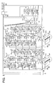
- FIG. 1 is a diagram of assistance in explaining an example in which an embodiment of the control apparatus in the event of a power failure according to the present invention is applied to an offset rotary press.
- FIG. 1 shows an offset rotary press comprising printing sections CT1 and CT2 each having four printing mechanisms P, a folding section FD for cutting and folding a printed continuous paper web W into predetermined printing images, and paper feeding sections SP1 and SP2 provided for each of the printing section CT1 and CT2 for feeding the paper web W as a printing material to the corresponding printing sections CT1 and CT2.
- Each of the printing mechanisms P in the printing sections CT1 and CT2 has two sets of printing couples of blanket cylinders BC and plate cylinders PC.
- the plate cylinder PC of each printing couple is driven by a drive means M via a transmission means GT.
- the blanket cylinder BC is driven by the drive means M via the plate cylinder PC and a transmission means (not shown) provided between both the plate cylinder PC and the blanket cylinder BC. That is, the printing mechanisms P in each of the printing sections CT1 and CT2 are driven separately by independent drive means M.
- an infeed roller IN In the vicinity of the upstream of each of the printing sections CT1 and CT2 provided is an infeed roller IN for feeding the paper web W to the corresponding printing section CT1 or CT2.
- an outfeed roller OT for pulling out the paper web W from the corresponding printing section CT1 or CT2; these rollers being driven by the drive means M via the transmission means GT.
- a first tension detecting means DN that is a tension detecting mechanism using a dancer roller, for example
- a second tension detecting means TP that is a tension detecting mechanism using a strain gauge, for example.
- a folding cylinder FC of the folding section FD is driven by the drive means M via the transmission means GT, and the other cylinders thereof by the drive means M via transmission means (not shown) provided between the folding cylinder FD and the other cylinders.
- a nipping roller NI for feeding the paper web W into a gap between the folding cylinder FD and the other cylinders that are in close contact with each other.
- a drag roller DR for feeding the paper web W to the folding section FD; all these rollers being driven by the drive means M via the transmission means GT.
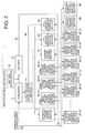
- Each of the drive means M has (i) a printing couple drive source control section 30 for #11 ⁇ #18 and #21 ⁇ #28, (ii) an infeed roller drive source control section 31 for #10 and #20, (iii) an outfeed roller drive source control section 32 for #19 and #29, (iv) a drag roller drive source control section 33 for #97, (v) a nipping roller drive source control section 34 for #97, and (vi) a folding cylinder drive source control section 35 for #99.
- a rotary encoder with Z phase (an incremental encoder; hereinafter referred to as an encoder) EN that is a feedback signal output section for outputting a first pulse signal as many as the number proportional to the rotational angular displacement of the drive means M and outputting a second pulse signal (Z-phase pulse signal) per rotation is also provided.
- the drive source control section 3 is connected to the rotation control signal output section 2 via an input-side interface 36 which will be described with reference to FIG. 5 and a connecting cable 92.
- a blanket cylinder changeover mechanism 6 that is a blanket cylinder moving mechanism using an air cylinder for selectively moving the blanket cylinder BC so as to cause the blanket surface of the blanket cylinder BC to make contact with, or detach from the paper web W is provided on each printing couple of the printing sections CT1 and CT2.
- Each of the blanket cylinder changeover mechanism 6 is connected to a moving mechanism control section 60 for controlling the operation of the blanket cylinder changeover mechanism 6 on the printing section CT1 or CT2.
- the rotating members PR are connected to a rotating member pushing mechanism 7, which is connected via a connecting piping 94 to a forcing pressure control section 70 for changing over the forcing pressure for forcing the paper web W onto the drag roller DR by the rotating members PR.
- a printing material braking mechanism 8 having an air-operated brake, for example.
- the printing material braking mechanism 8 is connected via a connecting piping 95 to a printing material braking control section 80 for changing over braking forces for the paper web W.
- an uninterruptible power supply 1 connected to an external power supply (not shown) is provided.
- the uninterruptible power supply 1 has a converter 11 on the power input side thereof, an inverter 13 on the power output side thereof, a battery power supply 12 and a power failure signal output section 14.
- the uninterruptible power supply 1 converts in the converter 11 the a-c power fed from the external power supply into d-c power, which is in turn stored in the battery power supply 12, and reconverts the converted d-c power into a-c power in the inverter 13 for output.
- the power failure signal output section 14 detects a voltage drop of power fed to the converter 11 due to a failure of the external power supply, and outputs a power failure signal.
- the power failure signal output by the power failure signal output section 14 is sent via a connecting cable 96 to the rotation control signal output section 2, the moving mechanism control section 60, and the pushing force control section 70.
- the drag roller drive source control apparatus 33 To the power output side of the uninterruptible power supply 1 connected via a connecting cable 91 are the drag roller drive source control apparatus 33, the moving mechanism control section 60, and the pushing force control section 70. Furthermore, the printing couple drive source control apparatus 30, the infeed roller drive source control apparatus 31, the outfeed roller drive source control apparatus 32, the nipping roller drive source control apparatus 34, the folding cylinder drive source control apparatus 35 and the printing material braking control section 80 are connected to an external power supply (not shown) via a connecting cable 90.
- a symbol AD shown in the upper middle of FIG. 1 refers to a gathering mechanism for cutting the paper web W at the across-the-width center thereof in the direction parallel to the longitudinal direction, and arranging the cut paper sheets in such a manner that positions of images on the sheets that form the basis of cutting in the folding section agree with each other in the longitudinal direction. Detailed description, however, is omitted here since this mechanism is not related to the present invention.
- the rotary press is operated as usual so long as no trouble occurs in the external power supply. That is, when the external power supply is turned on, power is fed via the connecting cable 90 to the uninterruptible power supply 1, the printing couple drive source control section 30, the infeed roller drive source control section 31, the outfeed roller drive source control section 32, the nipping roller drive source control section 34, the folding cylinder drive source control section 35 and the printing material braking control section 80.
- the uninterruptible power supply 1 Upon application of power, the uninterruptible power supply 1 converts the a-c power to d-c power in the converter 11 thereof, and reconverts the converted d-c power to a-c power, which is in turn fed to the rotation control signal output section 2, the drag roller drive source control section 33, the moving mechanism control section 60 and the pushing force control section 70.
- the power converted from a-c to d-c is stored in the battery power supply 12.
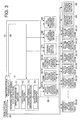
- a rotary press operation signal such as start and then increase the speed, is input from the input operation section 21 of the rotation control signal output section 2 (refer to FIG. 3) to operate the rotary press.
- the rotation control signal output section 2 into which the operation signal was input gives an instruction to the control signal generating section 23 to output a control signal corresponding to the operation signal input by the processing section 22, such as a reference pulse signal indicating the rotation reference.
- the control signal generating section 23 Upon receipt of the signal output instruction given by the processing section 22, the control signal generating section 23 outputs a control signal in accordance with the instruction. This signal is output to the connecting cable 92 via an output-side interface 24.
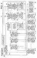
- the signal output to the connecting cable 92 by the rotation control signal output section 2 is input to each drive source control section 3 via the input-side interface 36, as shown in FIG. 5.
- the drive source control section 3 receiving the signal output by the rotation control signal output section 2 processes the signal in the processing section 37 to extract a reference phase and a reference speed, extracts the phase and speed at that point of time of the corresponding drive means M from a first pulse signal and a second pulse signal output by the encoder EN, compares the phase at that point of time of the drive means M with the extracted reference phase, compares the speed at that point of time of the drive means M with the reference speed, outputs a corrected signal that corrected the reference speed to eliminate the speed and phase differences, and feeds an appropriate drive power corresponding to the corrected signal to the drive means M via an amplifier 38.
- the infeed roller drive source control section 31 of the drive source control section 3 also receives and corrects the output signal of the first tension detecting means DN, whereas the outfeed roller drive source control section 32 also receives and corrects the output signal of the second tension detecting means TP when correcting the reference speed.
- the moving mechanism control section 60 changes over a blanket cylinder changeover solenoid valve 61 at a predetermined appropriate timing after the start of the rotary press to operate the blanket cylinder changeover mechanism 6, bringing and maintaining the blanket surface of the blanket cylinder BC into contact with the paper web W that is being traveled under the synchronous operation.
- the pushing force control section 70 feed a predetermined air pressure to the rotating member pushing mechanism 7 with an electro-pneumatic converter 71 along with the start of the rotary press to push the rotating member PR to the drag roller DR, forcing the paper web W that is guided in contact with the drag roller DR onto the drag roller DR via the rotating member PR.
- the printing material braking control section 80 changes over a printing material braking solenoid valve 81 in accordance with the diameter of the web roll WR of the paper web W at the start of printing to operate the printing material braking mechanism 8 so that braking is accomplished in accordance with the diameter of the web roll WR of the paper web W at the start of printing, while adjusting at all times air pressure fed to the printing material braking mechanism 8 in accordance with the paper-feeding tension detected by a publicly known paper-feeding tension detecting means (not shown).
- the diameter of the web roll WR of the paper web W at the start of printing may be detected with an appropriate publicly known detecting means (not shown).
- the apparatus for controlling the rotary press in a power failure as shown in FIG. 1 starts control operation in the following manner.
- the uninterruptible power supply 1 outputs a power failure signal as the power failure signal output section 14 detects a drop of the voltage of power into the converter 11, and the battery power supply 12 outputs a d-c power, which is converted into an a-c power in the inverter 13.
- the power failure signal output by the uninterruptible power supply 1 is input to the rotation control signal output section 2, the moving mechanism control section 60, and the pushing force control section 70 via the connecting cable 96, while the a-c power, based on the d-c power from the battery power supply 12, output by the uninterruptible power supply 1 is input to the rotation control signal output section 2, the drag roller drive source control section 33, the moving mechanism control section 60 and the pushing force control section 70 via the connecting cable 91.
- the rotation control signal output section 2 to which the power failure signal and the a-c power based on the d-c power of the battery power supply 12 output by the uninterruptible power supply 1 have been simultaneously input, outputs a signal indicating a rotation reference for causing the driving means M to rotate so that those driven components are decelerated and stopped in a predetermined time, 15 seconds, for example.
- the drag roller drive source control section 33 to which the a-c power based on the d-c power of the battery power supply 12 output by the uninterruptible power supply 1 is input, controls the rotation of the drag roller DR in accordance with the signal output by the uninterruptible power supply 1 for indicating the rotation reference for rotating to decelerate and stop the drive means M.
- the pushing force control section 70 to which the power failure signal and the a-c power based on the d-c power of the battery power supply 12 output by the uninterruptible power supply 1 have been input, maintains the air pressure that was predetermined in the electro-pneumatic converter 71, or changes the air pressure that was predetermined by the electro-pneumatic converter 71 to a higher value to supply to the rotating member pushing mechanism 7 so as to force the rotating member PR onto the drag roller DR, thereby keeping the state that the paper web W is kept forced onto the drag roller DR via the rotating member PR. Consequently, even after a trouble occurs in the external power supply, the drag roller DR keeps tensioning the paper web W while decelerating under controlled rotation, and eventually bringing the paper web W to a halt.
- the moving mechanism control section 60 to which the power failure signal and the a-c power based on the d-c power of the battery power supply 12 output by the uninterruptible power supply 1 have been input, immediately changes over the blanket cylinder movement changeover solenoid valve 61, actuating the blanket cylinder changeover mechanism 6 to separate the blanket surface of the blanket cylinder BC away from the paper web W and maintain that state, as shown in FIG. 4.
- the printing couple drive source control section 30, the infeed roller drive source control section 31, the outfeed roller drive source control section 32, the nipping roller drive source control section 34 and the folding cylinder drive source control section 35 stops the control operation as power supply to them has been interrupted. Consequently, both the plate cylinder PC and the blanket cylinder BC constituting a printing couple, the infeed roller IN, and the outfeed roller OT are changed over from the controlled rotation by the drive means M to the rotation by inertial force. However, since the blanket surface of the blanket cylinder BC is separated from the paper web W, as described above, there is no fear of the large and uneven tension produced by the rotation of the printing couple being exerted onto the paper web W.
- the printing material braking control section 80 to which power supply has been interrupted, is changed over to a state where the printing material braking mechanism 8 gives full play to the braking function thereof independently of the diameter of the web roll WR of the paper web W or of the paper feeding tension as the printing material braking solenoid valve 81 is changed by a built-in spring.
- the paper web W separated from the blanket cylinder BC is tensioned by the controlled rotation of the drag roller DR under the state where the printing material braking mechanisms 8 of the paper feeding sections SP1 and SP2 give full play to the maximum braking function thereof, and brought to a halt within a predetermined time. Since no uneven and large tension is exerted until the rotary press is stopped, there is no fear of the breakage of the paper web W.
- the power failure signal and the a-c power based on the d-c power of the battery power supply 12 output by the uninterruptible power supply 1 may be applied to the drag roller drive source control section 33, and to the infeed roller drive source control section 31, the outfeed roller drive source control section 32, the nipping roller drive source control section 34 and the folding cylinder drive source control section 35 to cause the drive means M corresponding to each of these to perform the same control as the control of the drive means M for the drag roller DR by the drag roller drive source control section 33.
- the drive means M for driving the printing couple drive source control section 3 and the printing couples may be adapted to perform similar operations.
- the present invention makes it possible to apply to an electrically synchronous-controlled shaftless rotary press to eliminate, in case power feeding is interrupted in a main power failure, the breakage of a paper web due to an uneven tension exerted onto the paper web that travels in the rotary press.
- the broken paper web is prevented from being wound on the rotary component of the rotary press, allowing the rotary press to resume printing operation immediately after the power is restored, eliminating major troubles in high-speed, timely printing operations, such as newspaper printing.
- the present invention is also extremely effective in improving the operating efficiency of the rotary press.
Landscapes
- Engineering & Computer Science (AREA)
- Mechanical Engineering (AREA)
- Inking, Control Or Cleaning Of Printing Machines (AREA)
- Rotary Presses (AREA)
Applications Claiming Priority (2)
| Application Number | Priority Date | Filing Date | Title |
|---|---|---|---|
| JP2001109471A JP3577288B2 (ja) | 2001-04-09 | 2001-04-09 | 輪転機の停電時制御方法及び停電時制御装置 |
| JP2001109471 | 2001-04-09 |
Publications (2)
| Publication Number | Publication Date |
|---|---|
| EP1251005A2 true EP1251005A2 (fr) | 2002-10-23 |
| EP1251005A3 EP1251005A3 (fr) | 2004-03-03 |
Family
ID=18961408
Family Applications (1)
| Application Number | Title | Priority Date | Filing Date |
|---|---|---|---|
| EP02251318A Withdrawn EP1251005A3 (fr) | 2001-04-09 | 2002-02-26 | Procédé et dispositif de contrôle des presses rotatives pendant des coupures de courant |
Country Status (3)
| Country | Link |
|---|---|
| US (1) | US6615730B2 (fr) |
| EP (1) | EP1251005A3 (fr) |
| JP (1) | JP3577288B2 (fr) |
Cited By (2)
| Publication number | Priority date | Publication date | Assignee | Title |
|---|---|---|---|---|
| DE102007039915A1 (de) * | 2007-07-13 | 2009-01-15 | Wifag Maschinenfabrik Ag | Verfahren und Vorrichtung zum Stillsetzen einer Druckmaschine bei Netzausfall |
| EP2840676A1 (fr) * | 2011-02-04 | 2015-02-25 | manroland web systems GmbH | Procédé destiné à l'immobilisation d'une imprimante à rouleaux |
Families Citing this family (7)
| Publication number | Priority date | Publication date | Assignee | Title |
|---|---|---|---|---|
| JP3662852B2 (ja) * | 2001-01-11 | 2005-06-22 | 株式会社東京機械製作所 | 印刷画像情報に基づいて制御対象を選択する輪転機の同期制御装置 |
| JP2002361838A (ja) * | 2001-06-13 | 2002-12-18 | Tokyo Kikai Seisakusho Ltd | 停電時制御が可能な輪転機の制御装置 |
| DE102005041919B4 (de) * | 2005-09-03 | 2008-05-29 | Baldwin Germany Gmbh | Bahnbruch-Überwachungseinrichtung für Rollenrotationsdruckmaschinen |
| US7287473B2 (en) * | 2005-12-20 | 2007-10-30 | Heidelberger Druckmaschinen Ag | Method for selecting printing material in a printing press and printing press |
| JP5355976B2 (ja) * | 2008-09-24 | 2013-11-27 | 三菱重工印刷紙工機械株式会社 | 輪転印刷機および輪転印刷機の停電制御方法 |
| JP2010167714A (ja) * | 2009-01-23 | 2010-08-05 | Mitsubishi Heavy Ind Ltd | 幅見当修正装置およびこれを備えた印刷機 |
| DE102009041485A1 (de) * | 2009-09-14 | 2011-04-14 | Heidelberger Druckmaschinen Ag | Papierfreie Druckmaschine bei Stromausfall |
Family Cites Families (14)
| Publication number | Priority date | Publication date | Assignee | Title |
|---|---|---|---|---|
| US2944644A (en) * | 1956-06-04 | 1960-07-12 | Electric Eye Equipment Company | Multi-unit printing-press drive |
| JPS6036946A (ja) | 1983-08-08 | 1985-02-26 | Mitsubishi Electric Corp | 空燃比制御装置 |
| JPS60171006A (ja) * | 1984-02-15 | 1985-09-04 | 松下電工株式会社 | ヘアセツト器 |
| DE3541275A1 (de) * | 1985-11-22 | 1987-05-27 | Heidelberger Druckmasch Ag | Steuerschaltung fuer einen elektrischen druckmaschinenantriebsmotor oder dergleichen |
| JPH0337650A (ja) | 1989-07-04 | 1991-02-19 | Fujitsu Ltd | マスク・レチクルの欠陥検査装置 |
| JPH0359081A (ja) | 1989-07-28 | 1991-03-14 | Teikoku Ink Seizo Kk | 水無し平版用減感インキ |
| US5365844A (en) * | 1993-07-29 | 1994-11-22 | Rockwell International Corporation | Device for controlling a web in a printing press |
| DE4417661C2 (de) * | 1994-05-20 | 1996-06-05 | Koenig & Bauer Albert Ag | Anordnung zum Verhindern von Druckwerksschäden bei einer Rollenrotationsdruckmaschine |
| DE4430693B4 (de) | 1994-08-30 | 2005-12-22 | Man Roland Druckmaschinen Ag | Antriebe für eine Rollenrotations-Offsetdruckmaschine |
| DE19600110A1 (de) * | 1995-08-10 | 1997-07-10 | Baumueller Nuernberg Gmbh | Elektrisches Antriebssystem und Sicherheitsmodul insbesondere in einer Druckmaschine |
| DE19702963B4 (de) * | 1996-02-07 | 2006-06-08 | Koenig & Bauer Ag | Antrieb für eine Rollenrotationsdruckmaschine |
| JP3037650B2 (ja) * | 1997-10-29 | 2000-04-24 | 株式会社東京機械製作所 | 輪転機の印刷ユニットの駆動装置 |
| JP3183871B2 (ja) * | 1999-08-30 | 2001-07-09 | 株式会社東京機械製作所 | 輪転機のネットワーク型同期制御装置 |
| US6684778B2 (en) * | 2001-05-25 | 2004-02-03 | Ryobi, Ltd. | Printing press with a sheet-turning-over-mechanism |
-
2001
- 2001-04-09 JP JP2001109471A patent/JP3577288B2/ja not_active Expired - Lifetime
-
2002
- 2002-02-25 US US10/084,771 patent/US6615730B2/en not_active Expired - Fee Related
- 2002-02-26 EP EP02251318A patent/EP1251005A3/fr not_active Withdrawn
Cited By (3)
| Publication number | Priority date | Publication date | Assignee | Title |
|---|---|---|---|---|
| DE102007039915A1 (de) * | 2007-07-13 | 2009-01-15 | Wifag Maschinenfabrik Ag | Verfahren und Vorrichtung zum Stillsetzen einer Druckmaschine bei Netzausfall |
| DE102007039915B4 (de) * | 2007-07-13 | 2012-03-29 | Wifag Maschinenfabrik Ag | Verfahren und Vorrichtung zum Stillsetzen einer Druckmaschine bei Netzausfall |
| EP2840676A1 (fr) * | 2011-02-04 | 2015-02-25 | manroland web systems GmbH | Procédé destiné à l'immobilisation d'une imprimante à rouleaux |
Also Published As
| Publication number | Publication date |
|---|---|
| US6615730B2 (en) | 2003-09-09 |
| US20020144609A1 (en) | 2002-10-10 |
| JP2002307663A (ja) | 2002-10-23 |
| JP3577288B2 (ja) | 2004-10-13 |
| EP1251005A3 (fr) | 2004-03-03 |
Similar Documents
| Publication | Publication Date | Title |
|---|---|---|
| EP1182159B1 (fr) | Dispositif pour ajuster l'écartement de deux rouleaux | |
| US5699735A (en) | Web-fed rotary press | |
| JPH0742019B2 (ja) | 輪転機における料紙走行張力および料紙切断位置の制御装置 | |
| US6615730B2 (en) | Method and apparatus for controlling rotary presses in power failure | |
| US6408757B2 (en) | Paper roll braking device | |
| EP2337686A1 (fr) | Section pour transporter des produits imprimés de découpes variables dans une plieuse pour machine à imprimer | |
| JP5134275B2 (ja) | 輪転印刷機 | |
| JP2001080054A (ja) | 多色刷平版輪転機における胴逃がし・胴入れ制御装置 | |
| JP3893372B2 (ja) | シャフトレス輪転機における停電時の断紙等防止方法及びその装置 | |
| JPS61144350A (ja) | 輪転機印刷機に於る版及びインキ換え方法 | |
| JP2006224413A (ja) | グラビア印刷機およびテンション制御方法 | |
| JP2008023751A (ja) | 輪転印刷機およびその運転方法 | |
| US7707917B2 (en) | Method and devices for severing sheets from and/or feeding a web into a subsequent processing stage | |
| EP4506122A1 (fr) | Méthode de découpe, de refoulage et/ou de gaufrage d'un carton et machine de traitement du carton | |
| JP3795053B2 (ja) | 輪転機及び輪転機の制御方法 | |
| JP4728410B2 (ja) | 輪転機の連続紙走行張力調整方法及び連続紙走行張力調整装置 | |
| US6769359B2 (en) | Paper-web holding apparatus for rotary printing press | |
| JP3730532B2 (ja) | 輪転機及び輪転機の制御方法 | |
| JP2021031295A (ja) | 輪転印刷機及び輪転印刷機の制御方法 | |
| JP3825460B2 (ja) | 輪転印刷機 | |
| US7540239B2 (en) | Web-fed rotary printing unit | |
| US8661976B2 (en) | Method for controlling a rotary press and rotary press | |
| JP2005319811A (ja) | 輪転印刷機 | |
| JP2002086683A (ja) | 印刷機械の運転方法 |
Legal Events
| Date | Code | Title | Description |
|---|---|---|---|
| PUAI | Public reference made under article 153(3) epc to a published international application that has entered the european phase |
Free format text: ORIGINAL CODE: 0009012 |
|
| AK | Designated contracting states |
Kind code of ref document: A2 Designated state(s): AT BE CH CY DE DK ES FI FR GB GR IE IT LI LU MC NL PT SE TR |
|
| AX | Request for extension of the european patent |
Free format text: AL;LT;LV;MK;RO;SI |
|
| PUAL | Search report despatched |
Free format text: ORIGINAL CODE: 0009013 |
|
| AK | Designated contracting states |
Kind code of ref document: A3 Designated state(s): AT BE CH CY DE DK ES FI FR GB GR IE IT LI LU MC NL PT SE TR |
|
| AX | Request for extension of the european patent |
Extension state: AL LT LV MK RO SI |
|
| RIC1 | Information provided on ipc code assigned before grant |
Ipc: 7B 41F 13/016 B Ipc: 7B 41F 33/06 B Ipc: 7B 41F 33/12 B Ipc: 7B 41F 13/004 A |
|
| 17P | Request for examination filed |
Effective date: 20040301 |
|
| AKX | Designation fees paid |
Designated state(s): DE GB |
|
| STAA | Information on the status of an ep patent application or granted ep patent |
Free format text: STATUS: THE APPLICATION IS DEEMED TO BE WITHDRAWN |
|
| 18D | Application deemed to be withdrawn |
Effective date: 20100901 |