EP1273784A2 - Zylinderkopf für eine viertakt Brennkraftmaschine - Google Patents
Zylinderkopf für eine viertakt Brennkraftmaschine Download PDFInfo
- Publication number
- EP1273784A2 EP1273784A2 EP02009887A EP02009887A EP1273784A2 EP 1273784 A2 EP1273784 A2 EP 1273784A2 EP 02009887 A EP02009887 A EP 02009887A EP 02009887 A EP02009887 A EP 02009887A EP 1273784 A2 EP1273784 A2 EP 1273784A2
- Authority
- EP
- European Patent Office
- Prior art keywords
- valve
- fitted
- cylinder head
- depth
- exhaust
- Prior art date
- Legal status (The legal status is an assumption and is not a legal conclusion. Google has not performed a legal analysis and makes no representation as to the accuracy of the status listed.)
- Granted
Links
Images


Classifications
-
- F—MECHANICAL ENGINEERING; LIGHTING; HEATING; WEAPONS; BLASTING
- F02—COMBUSTION ENGINES; HOT-GAS OR COMBUSTION-PRODUCT ENGINE PLANTS
- F02B—INTERNAL-COMBUSTION PISTON ENGINES; COMBUSTION ENGINES IN GENERAL
- F02B75/00—Other engines
- F02B75/16—Engines characterised by number of cylinders, e.g. single-cylinder engines
- F02B75/18—Multi-cylinder engines
- F02B75/22—Multi-cylinder engines with cylinders in V, fan, or star arrangement
-
- F—MECHANICAL ENGINEERING; LIGHTING; HEATING; WEAPONS; BLASTING
- F02—COMBUSTION ENGINES; HOT-GAS OR COMBUSTION-PRODUCT ENGINE PLANTS
- F02F—CYLINDERS, PISTONS OR CASINGS, FOR COMBUSTION ENGINES; ARRANGEMENTS OF SEALINGS IN COMBUSTION ENGINES
- F02F1/00—Cylinders; Cylinder heads
- F02F1/24—Cylinder heads
- F02F1/42—Shape or arrangement of intake or exhaust channels in cylinder heads
- F02F1/4214—Shape or arrangement of intake or exhaust channels in cylinder heads specially adapted for four or more valves per cylinder
-
- F—MECHANICAL ENGINEERING; LIGHTING; HEATING; WEAPONS; BLASTING
- F02—COMBUSTION ENGINES; HOT-GAS OR COMBUSTION-PRODUCT ENGINE PLANTS
- F02B—INTERNAL-COMBUSTION PISTON ENGINES; COMBUSTION ENGINES IN GENERAL
- F02B75/00—Other engines
- F02B75/02—Engines characterised by their cycles, e.g. six-stroke
- F02B2075/022—Engines characterised by their cycles, e.g. six-stroke having less than six strokes per cycle
- F02B2075/027—Engines characterised by their cycles, e.g. six-stroke having less than six strokes per cycle four
-
- F—MECHANICAL ENGINEERING; LIGHTING; HEATING; WEAPONS; BLASTING
- F02—COMBUSTION ENGINES; HOT-GAS OR COMBUSTION-PRODUCT ENGINE PLANTS
- F02B—INTERNAL-COMBUSTION PISTON ENGINES; COMBUSTION ENGINES IN GENERAL
- F02B2275/00—Other engines, components or details, not provided for in other groups of this subclass
- F02B2275/18—DOHC [Double overhead camshaft]
Definitions
- the present invention relates to a cylinder head in which at least one of plural valve guides for guiding intake and exhaust poppet valves in an opened or closed direction so that they can be slid is fitted in different depth in an overhead camshaft (OHC) four-stroke internal combustion engine provided with a valve lifter, particularly relates to a cylinder head of a four-stroke internal combustion engine in which a valve pause mechanism is provided to an intake poppet valve or an exhaust poppet valve fitted into a shallow valve guide in the depth of a fitted part.
- OOC overhead camshaft
- valve lifter springs 03, 04 that always press intake and exhaust poppet valves 01, 02 in a closed direction are different between the position of the valve lifter provided with a valve pause mechanism 05 and the position of the valve lifter without the valve pause mechanism 05, and as the valve lifter spring 03 provided to the intake or exhaust poppet valve 01 provided with the valve pause mechanism 05 is positioned lower by the quantity of the valve pause mechanism 05 attached to the valve lifter 00 of the intake or exhaust poppet valve 01, a valve guide 06 for guiding the intake or exhaust poppet valve 01 so that it can be slid is shorter, compared with a valve guide 07 on the side provided with no valve pause mechanism 05 (refer to Japanese published unexamined patent application No. 2000-205038).
- the longer valve guide 07 for guiding the intake or exhaust poppet valve 02 provided with no valve pause mechanism 05 so that it can be slid is required to be press-fitted into a fitting hole 09 deeper in a cylinder head 08 by longer quantity, the press fitting resistance is remarkably larger, compared with press fitting resistance in which the valve guide 06 of the intake or exhaust poppet valve 01 provided with the valve pause mechanism 05 is press-fitted and the press fit depth is deeper.
- the setting of the press fit time of each valve guide 06, 07 is different, the management of the manufacturing process is complex and is not easy.
- the invention relates to the improvement of a cylinder head of a four-stroke internal combustion engine in which such a problem is solved
- the invention according to Claim 1 is based upon a cylinder head of a four-stroke internal combustion engine in which plural valve guides for guiding and supporting intake and exhaust poppet valves in an opened or closed direction so that they can be slid have substantially uniform thickness in the longitudinal direction of the valve guide and depth in which at least one of the plural valve guides is fitted in the cylinder head is different from depth in which the other valve guide is fitted in the cylinder head and is characterized in that an idle fitting hole having depth acquired by subtracting depth substantially equal to the depth of the shallower fitted part from the depth of the deeper fitted part and thicker than the valve guide is formed from the end face of a fitted part on the side of a valve spring toward an inlet port or an exhaust port in the cylinder head.
- valve guides can be press-fitted at uniform press fit depth in the cylinder head independent of the length of a specific valve guide even if the specific valve guide out of the plural valve guides is long.
- a long valve guide for guiding an intake or exhaust poppet valve provided with no valve pause mechanism so that it can be slid can be press-fitted with the same strength, in the same length, therefore, in the same required time as the press fitting of a short valve guide for guiding an intake or exhaust poppet valve provided with a valve pause mechanism so that it can be slid by configuring the invention as in Claim 2.
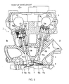
- An OHC four-stroke internal combustion engine 1 mounted in a motorcycle not shown is a fore and after V-type internal combustion engine in which a crankshaft (not shown) is directed in a direction of the body width and a cylinder on the front side of a vehicle body and a cylinder on the rear side of the vehicle body make a right included angle before and behind as shown in Fig.
- the body of the OHC four-stroke internal combustion engine 1 is composed of a cylinder block 2, a crankcase 3 integrated with the cylinder block 2 on the lower surface of the cylinder block 2, a pair of two cylinder heads 4 integrated with the respective head end of a cylinder bank on the front side of the vehicle body and a cylinder bank on the rear side of the vehicle body in the cylinder block 2 and a pair of two head covers 5 that respectively cover the heads of the cylinder heads 4.
- the cylinder blocks 2 which are installed on the front side of the vehicle body and on the rear side of the vehicle body and in each of which two cylinder holes 6 are arranged in the direction of the body width as shown in Fig. 2 (only the cylinder block on the front side of the vehicle body out of the cylinder blocks on the front side and the rear side is shown) form the four-cylinder OHC four-stroke internal combustion engine 1, a pent roof type concave portion 7 is respectively formed in a location corresponding to the cylinder hole 6 on the lower surface of each cylinder head 4 located on the front side and on the rear side of the vehicle body as shown in Figs. 3 to 5 and a combustion chamber 8 is formed by a piston (not shown) fitted into the cylinder hole 6, the cylinder hole 6 and the concave portion 7.
- each cylinder bank on the front side and on the rear side of the vehicle body of the V-type four-cylinder OHC four-stroke internal combustion engine 1 an intake system (not shown) including a carburetor and an intake chamber is arranged on the side of a cylinder included angle (on the side in contact with fore and after V-type space A shown in Fig. 1, that is, the space A between the cylinder bank on the front side of the vehicle body and the cylinder bank on the rear side of the vehicle body), and an exhaust pipe not shown is connected outside each cylinder bank on the front side and on the rear side of the vehicle body (the outside B of the fore and after V-type space A).
- one intake passage on the upstream side connected to the intake system is branched into two intake passages on the downstream side of intake and an inlet port 9 open to the combustion chamber 8 in two locations is formed
- two exhaust passages on the upstream side open to the combustion chamber 8 in two locations are integrated in one exhaust passage on the downstream side of exhaust and an exhaust port 10 connected to the exhaust pipe not shown is formed, and as shown in Figs.
- intake poppet valves 13a and 13b and exhaust poppet valves 14a and 14b that respectively seal two inlet openings 11a and 11b and two exhaust openings 12a and 12b so that the valves can be opened or closed are provided to the cylinder head 4.
- An inlet port and an exhaust port reverse in fore and after positions to the inlet port 9 and the exhaust port 10 in the cylinder head 4 on the front side of the vehicle body are also formed in the cylinder head 4 on the rear side of the vehicle body. That is, on the front side of the vehicle body of the cylinder head 4 on the rear side of the vehicle body, the inlet port (not shown) in the same shape as that of the inlet port 9 on the rear side of the vehicle body of the cylinder head 4 on the front side of the vehicle body is formed, and on the rear side of the vehicle body of the cylinder head 4 on the rear side of the vehicle body, the exhaust port (not shown) in the same shape as that of the exhaust port 10 on the front side of the vehicle body of the cylinder head 4 on the front side of the vehicle body is formed.
- the intake poppet valve 13a always opened or closed to which a valve lifter 17 without a valve pause mechanism shown in Figs. 3 to 5 is attached is provided to the inlet opening 11a located on the outside of the vehicle body in each cylinder hole 6, and the exhaust poppet valve 14a the opening or the closing of which can be paused and to which a valve lifter 18 with the valve pause mechanism shown in Figs. 3 to 5 is attached is provided to the exhaust opening 12a located on the outside of the vehicle body in each cylinder hole 6.
- the intake poppet valve 13b to which the valve lifter 18 with the valve pause mechanism is attached is provided to the inlet opening 11b located on the inside of the vehicle body in each cylinder hole 6 reversely to the inlet opening 11a on the outside of the vehicle body, and the valve lifter 17 without the valve pause mechanism is attached to the exhaust opening 12b located on the inside of the vehicle body in each cylinder hole 6 reversely to the exhaust opening 12a on the outside of the vehicle body (not shown in the longitudinal sectional view).
- An inlet camshaft 19 is arranged over an extension of a stem 15a of the intake poppet valve 13a
- an exhaust camshaft 20 is arranged over an extension of a stem 16a of the exhaust poppet valve 14a
- the inlet camshaft 19 and the exhaust camshaft 20 are attached to the cylinder head 4 respectively by a camshaft holder 23 located in the center in the direction of the body width and a camshaft holder 24 located on the right side in the direction of the body width so that the respective camshafts can be rotated as shown in Fig.
- an inlet cam 21a of the inlet camshaft 19 and an exhaust cam 22a of the exhaust camshaft 20 every cylinder hole 6 are touched to each top face of the valve lifter 17a without the valve pause mechanism of the intake poppet valve 13a and the valve lifter 18a with the valve pause mechanism of the exhaust poppet valve 14a, a driven sprocket 25 is respectively integrated with the inlet camshaft 19 and the exhaust camshaft 20 at the right end of the vehicle body, a chain without an end not shown is laid between a drive sprocket (not shown) integrated with a crankshaft not shown and the driven sprocket 25, and when the OHC four-stroke internal combustion engine 1 is operated, an inlet cam 21 and an exhaust cam 22 are rotated at speed equivalent to a half of the rotational speed of the crankshaft and in the same direction.
- each contact surface of the cylinder head 4 and the camshaft holder 23 or 24 is a plane tying the center of the inlet camshaft 19 and the center of the exhaust camshaft 20, and each contact surface of the cylinder head 4 and the camshaft holder 23 or 24 is made parallel to each contact surface of the cylinder block 2 and the cylinder head 4. Therefore, distance from the top wall 32 of the valve lifter 17 without the valve pause mechanism to the inlet opening 11 and distance from the top wall 40 of the valve lifter 18 with the valve pause mechanism to the exhaust opening 12 are made substantially equal.
- valve pause mechanism 41 is not provided to the valve lifter 17a without the valve pause mechanism attached to the stem 15a of the intake poppet valve 13a, a retainer 27 is integrally fitted to the top of the stem 15a via a cotter 28 adjacently under the lower surface of the top wall 32a of the valve lifter 17a without the valve pause mechanism.
- a retainer 35 is integrated fitted via a cotter 36 further under the valve pause mechanism 41 under the top wall 40 of the valve lifter 18a with the valve pause mechanism.
- valve lifter springs 30 and 31 for pressing the intake poppet valve 13 and the valve lifter 17a without the valve pause mechanism upward and each length of a valve lifter spring 38 for pressing the exhaust poppet valve 14 upward and a valve lifter spring 39 for pressing the valve lifter 18a with the valve pause mechanism upward are set to substantially identical length so as to give a substantially identical spring load and a substantially identical characteristic.
- a valve guide cylinder 26a that guides and supports the stem 15a of the intake poppet valve 13a so that the stem can be slid is longer than a valve guide cylinder 34a that guides and supports the stem 16a of the exhaust poppet valve 14a so that the stem can be slid and in addition, a valve spring retainer 29 for supporting each lower end of the valve lifter springs 30 and 31 of the intake poppet valve 13a is located on the upside of a valve spring retainer 37 for supporting each lower end of the valve lifter springs 38 and 39 of the exhaust poppet valve 14a.
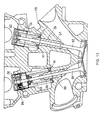
- the cylinder head 4 is cast so that a fitting hole 58 having a smaller diameter than the outside diameter of the valve guide cylinder 34a is formed in a part into which the valve guide cylinder 34a is fitted in the cylinder head 4 and a lower fitting hole 59 having a smaller diameter than the outside diameter of the valve guide cylinder 26a and having the same depth as the depth H 2 of the fitting hole 58 and an upper idle fitting hole 60 having a larger diameter than the outside diameter of the valve guide cylinder 26a are formed in a part into which the valve guide cylinder 26a is fitted in the cylinder head 4 are formed.
- Cutting work smaller than the respective outside diameters of the valve guide cylinders 34a and 26a by an amount of press fitting is applied to form the whole fitting hole 58 and the lower fitting hole 59 in the cylinder head 4, and over the fitting hole 59, if necessary, cutting work to an extent that the peripheral surface of the valve guide cylinder 26a is not touched to the upper idle fitting hole 60 at all is applied.
- the depth of the fitting hole 58 of the valve guide cylinder 34a is set to H 2 .
- the inside diameter of the idle fitting hole 60 is adjusted in a range from a minimum value of a diameter in which no interference with the valve guide 26a caused by the eccentricity of the fitting hole 59 occurs to a maximum value of the diameter in which area where no bucking occurs in the valve spring retainer 29 can be secured. Therefore, if the above-mentioned condition is met, the idle fitting hole 60 can be also formed by casting out in addition to cutting work.
- valve guide cylinder 34a and the valve guide cylinder 26a are respectively press-fitted into the fitting hole 58 and the lower fitting hole 59 in the cylinder head 4 with uniform press-in force in predetermined time.
- valve spring retainers 29 and 37 are fitted to the respective upper exposed parts of the valve guide cylinder 26a and the valve guide cylinder 34a, the two inside and outside valve lifter springs 30 and 31 are fitted in parallel between the retainer 27 and the valve spring retainer 29 and the two inside and outside valve lifter springs 38, 39 are fitted in parallel between the retainer 35 or the valve pause mechanism 41 and the valve spring retainer 37.
- the intake poppet valve 13 and the exhaust poppet valve 14 are pressed in a direction in which the inlet opening 11a of the inlet port 9 and the exhaust opening 12a of the exhaust port 10 are sealed by the spring of the valve lifter springs 30, 31 and the valve lifter springs 38, 39, and the top wall 32a of the valve lifter 17a without the valve pause mechanism and the top wall 40a of the valve lifter 18a with the valve pause mechanism are pressed in a direction in which the valve lifters are respectively touched to the inlet cam 21a and the exhaust cam 22a.
- a shim 33 is fitted between the top wall 32a of the valve lifter 17a without the valve pause mechanism and the top end of the stem 15a, a thicker part 57 slightly thicker than the peripheral part for functioning as a shim is formed in the center of the top wall 40a of the valve lifter 18a with the valve pause mechanism, the thicker shim part 57 is formed in various thickness and a few types of valve lifters 18a with the valve pause mechanism are prepared.
- valve pause mechanism 41 in the valve lifter 18 with the valve pause mechanism will be described.
- valve pause mechanism 41 is formed by a slide pin holder 43 shown in Fig. 7 fitted to a cylindrical peripheral wall 42 of the valve lifter 18a with the valve pause mechanism so that the slide pin holder can be moved in a direction (a vertical direction) in which the valve lifter 18a with the valve pause mechanism is slid, a slide pin 45 shown in Fig.
- a guide pin 47 that pierces the slide pin holder 43 and can be fitted into a guide groove 46 formed at one end of the slide pin 45
- a pin spring 49 that is fitted to the other end of the slide pin 45 and to the bottom of the pin hole 44 of the slide pin holder 43 and presses the bottom of the guide groove 46 of the slide pin 45 in a direction in which the bottom is touched to the guide pin 47
- a hydraulic drive unit 50 that presses the slide pin 45 toward the pin spring 49 against the spring in a stem through hole 48.
- the pressure oil passage 51 connected to a discharge port of a hydraulic pump (not shown) provided in the OHC four-stroke internal combustion engine 1 via a control valve (not shown) is formed in the cylinder head 4, a peripheral concave groove 53 is formed in a lifter guide hole 52 of the valve lifter 18 with the valve pause mechanism provided to the cylinder head 4, and the pressure oil passage 51 and the peripheral concave groove 53 communicate via a connecting hole 54.
- a side hole 55 that can communicate with the peripheral concave groove 53 of the lifter guide hole 52 is formed in the cylindrical peripheral wall 42 of the valve lifter 18 with the valve pause mechanism even if the valve lifter 18a with the valve pause mechanism is located in any location when the valve lifter 18a with the valve pause mechanism is vertically moved by the exhaust cam 22a. As shown in Fig.
- the peripheral concave groove 56 communicating with the side hole 55 is formed on the peripheral surface of the slide pin holder 43, the peripheral concave groove 56 communicates with an opening of the pin hole 44, in case pressure oil is supplied to the pressure oil passage 51, pressure oil is led to the opening of the pin hole 44 from the pressure oil passage 51 via the connecting hole 54, the peripheral concave groove 53, the side hole 55 and the peripheral concave groove 56, the slide pin 45 is moved toward the pin spring 49 against the spring force of the pin spring 49 with the pressure of the pressure oil (see Figs. 4, 5 and 10) and the stem 16a of the exhaust poppet valve 14a is fitted to the slide pin 45.
- valve lifter 18b with the valve pause mechanism is provided to the inlet port 11b located on the inside of the vehicle body reversely to the inlet port 11a on the outside of the vehicle body and the valve lifter 17b without the valve pause mechanism is provided to the exhaust port 12b located on the inside of the vehicle body.
- valve guide cylinders 26a and 34a are respectively press-fitted into the fitting holes 59 and 58 of the cylinder head 4 on the same press fitting conditions such as press fitting force and press fitting time. Therefore, the press fitting work and the control of the valve guide cylinders 26a and 34a are greatly simplified, the productivity is enhanced and in addition, the press fit quality is stably satisfactory.
- valve guide cylinder 26b for guiding and supporting a stem 15b of another intake poppet valve 13b so that the stem can be slid
- valve guide cylinder 34b for guiding and supporting a stem 16b of another exhaust poppet valve 14b so that the stem can be slid
- the height of the valve lifters 18a and 18b with the valve pause mechanism is reduced by the quantity and even if a valve included angle of the intake poppet valve 13 and the exhaust poppet valve 14 is reduced to reduce the combustion chamber 8 and increase compression ratio, the height of the cylinder head 4 is prevented from being increased and the large-sizing of the OHC four-stroke internal combustion engine 1 is avoided.
- valve lifters 17a and 17b without the valve pause mechanism have no valve pause mechanism 41
- the height of the valve lifters 17a and 17b without the valve pause mechanism can be equalized to that of the valve lifters 18a and 18b with the valve pause mechanism even if the shim 33 is provided, only one type of valve guide cylinder 34 is prepared for the valve lifters 17a and 17b without the valve pause mechanism, the stock management of the valve lifters 17a and 17b without the valve pause mechanism is simplified and the cost can be reduced.
- the invention provides a cylinder head in which any valve guide can be press-fitted in the cylinder head with substantially uniform press fit force based upon the cylinder head in which at least one valve guide out of plural valve guides for respectively guiding intake and exhaust poppet valves of an OHC four-stroke internal combustion engine provided with valve lifters so that the valve guide can be slid in a direction in which each valve is opened or closed is fitted differently in the depth of a fitted part.
- a cylinder head 4 of a four-stroke internal combustion engine 1 wherein plural valve guides 26a and 34a for guiding and supporting intake and exhaust poppet valves 15a and 16a so that they can be slid in a direction in which they are opened or closed have substantially uniform thickness in the respective longitudinal directions of the valve guides 26a and 34a and depth in which at least one valve guide 26a out of the plural valve guides 26a and 34a is fitted in the cylinder head 4 is different from depth in which another valve guide 34a is fitted in the cylinder head 4, an idle fitting hole 60 thicker than the valve guide is formed in depth H acquired by subtracting the depth H 2 of the shallower fitted part from the depth H 1 of the deeper fitted part from each end face of fitted parts on the sides of valve springs 30 and 31 toward an inlet port 9.
Landscapes
- Engineering & Computer Science (AREA)
- Chemical & Material Sciences (AREA)
- Combustion & Propulsion (AREA)
- Mechanical Engineering (AREA)
- General Engineering & Computer Science (AREA)
- Valve-Gear Or Valve Arrangements (AREA)
- Valve Device For Special Equipments (AREA)
- Cylinder Crankcases Of Internal Combustion Engines (AREA)
Applications Claiming Priority (2)
| Application Number | Priority Date | Filing Date | Title |
|---|---|---|---|
| JP2001205706 | 2001-07-06 | ||
| JP2001205706A JP4024018B2 (ja) | 2001-07-06 | 2001-07-06 | 4ストローク内燃機関のシリンダヘッド |
Publications (3)
| Publication Number | Publication Date |
|---|---|
| EP1273784A2 true EP1273784A2 (de) | 2003-01-08 |
| EP1273784A3 EP1273784A3 (de) | 2003-08-13 |
| EP1273784B1 EP1273784B1 (de) | 2006-11-29 |
Family
ID=19041965
Family Applications (1)
| Application Number | Title | Priority Date | Filing Date |
|---|---|---|---|
| EP02009887A Expired - Lifetime EP1273784B1 (de) | 2001-07-06 | 2002-05-02 | Zylinderkopf für eine viertakt Brennkraftmaschine |
Country Status (4)
| Country | Link |
|---|---|
| US (1) | US6691663B2 (de) |
| EP (1) | EP1273784B1 (de) |
| JP (1) | JP4024018B2 (de) |
| DE (1) | DE60216371T2 (de) |
Families Citing this family (6)
| Publication number | Priority date | Publication date | Assignee | Title |
|---|---|---|---|---|
| US20070137604A1 (en) * | 2005-12-21 | 2007-06-21 | Silseth John R | Motorcycle engine |
| JP4762091B2 (ja) * | 2006-09-05 | 2011-08-31 | 株式会社リケン | バルブ休止機構付きバルブリフタ |
| JP4627304B2 (ja) * | 2007-02-01 | 2011-02-09 | 愛知機械工業株式会社 | シリンダヘッドおよびこれを備える内燃機関 |
| KR20090051562A (ko) * | 2007-11-19 | 2009-05-22 | 현대자동차주식회사 | 가변 밸브 리프트 장치 |
| US8662033B2 (en) * | 2010-03-10 | 2014-03-04 | GM Global Technology Operations LLC | Modular engine assembly and fluid control assembly for hydraulically-actuated mechanism |
| JP5342592B2 (ja) * | 2011-03-31 | 2013-11-13 | 三菱重工業株式会社 | 内燃機関のシリンダ構造 |
Family Cites Families (5)
| Publication number | Priority date | Publication date | Assignee | Title |
|---|---|---|---|---|
| JPH02161147A (ja) * | 1988-08-01 | 1990-06-21 | Honda Motor Co Ltd | エンジンの燃料制御装置 |
| US5357916A (en) * | 1993-12-27 | 1994-10-25 | Chrysler Corporation | Valve adjuster mechanism for an internal combustion engine |
| US5655493A (en) * | 1996-01-16 | 1997-08-12 | Dresser Industries, Inc. | Exhaust valve for internal combustion engine |
| JP3482107B2 (ja) * | 1997-08-04 | 2003-12-22 | 本田技研工業株式会社 | 内燃機関の吸気装置 |
| JP4303342B2 (ja) * | 1999-01-11 | 2009-07-29 | 本田技研工業株式会社 | 自動二輪車用多気筒エンジン |
-
2001
- 2001-07-06 JP JP2001205706A patent/JP4024018B2/ja not_active Expired - Fee Related
-
2002
- 2002-05-02 EP EP02009887A patent/EP1273784B1/de not_active Expired - Lifetime
- 2002-05-02 DE DE60216371T patent/DE60216371T2/de not_active Expired - Lifetime
- 2002-06-06 US US10/162,875 patent/US6691663B2/en not_active Expired - Fee Related
Also Published As
| Publication number | Publication date |
|---|---|
| EP1273784B1 (de) | 2006-11-29 |
| DE60216371D1 (de) | 2007-01-11 |
| EP1273784A3 (de) | 2003-08-13 |
| JP4024018B2 (ja) | 2007-12-19 |
| JP2003020991A (ja) | 2003-01-24 |
| US6691663B2 (en) | 2004-02-17 |
| US20030005902A1 (en) | 2003-01-09 |
| DE60216371T2 (de) | 2007-03-15 |
Similar Documents
| Publication | Publication Date | Title |
|---|---|---|
| EP1057982A2 (de) | Viertakt-Brennkraftmaschine | |
| US6571758B2 (en) | Four-stroke internal combustion engine valve pause mechanism | |
| EP1273784B1 (de) | Zylinderkopf für eine viertakt Brennkraftmaschine | |
| EP1243780A2 (de) | Brennkraftmaschine | |
| US6378483B1 (en) | Lubrication system for four-stroke engine | |
| US5027753A (en) | Intake system of multi-cylinder internal combustion engine | |
| JPH1047155A (ja) | 内燃機関のシリンダヘッド装置 | |
| US6142116A (en) | Internal combustion engine with cylinder head having unique head bolt mounting and port arrangement | |
| JP2917274B2 (ja) | 4サイクルエンジンのシリンダヘッド | |
| US6189503B1 (en) | Porting arrangement for direct injected engine | |
| EP1344930A2 (de) | Brennkraftmaschine mit Kraftstoffeinspritzventil | |
| EP1243760A2 (de) | Brennkraftmaschine | |
| US6705265B2 (en) | Four-stroke internal combustion engine with valve resting mechanism | |
| JPH11257089A (ja) | 直噴式ディーゼル機関 | |
| US6209512B1 (en) | Small-dimension two or four stroke vehicle engine with stratified feed | |
| JP2009108826A (ja) | ガス燃料内燃機関 | |
| JPS6212812Y2 (de) | ||
| JPH0121326B2 (de) | ||
| JP2009108827A (ja) | ガス燃料内燃機関 | |
| JPH051807U (ja) | エンジンのシリンダヘツド構造 | |
| JP5586087B2 (ja) | 内燃機関の可変動弁機構 | |
| JPH06167207A (ja) | エンジンの潤滑装置 | |
| JPS61250311A (ja) | 内燃機関のバルブ作動制御装置 | |
| JPH11218053A (ja) | 内燃機関のシリンダヘッド | |
| JPH02123237A (ja) | 4サイクルエンジン |
Legal Events
| Date | Code | Title | Description |
|---|---|---|---|
| PUAI | Public reference made under article 153(3) epc to a published international application that has entered the european phase |
Free format text: ORIGINAL CODE: 0009012 |
|
| AK | Designated contracting states |
Kind code of ref document: A2 Designated state(s): AT BE CH CY DE DK ES FI FR GB GR IE IT LI LU MC NL PT SE TR |
|
| AX | Request for extension of the european patent |
Free format text: AL;LT;LV;MK;RO;SI |
|
| PUAL | Search report despatched |
Free format text: ORIGINAL CODE: 0009013 |
|
| AK | Designated contracting states |
Designated state(s): AT BE CH CY DE DK ES FI FR GB GR IE IT LI LU MC NL PT SE TR |
|
| AX | Request for extension of the european patent |
Extension state: AL LT LV MK RO SI |
|
| 17P | Request for examination filed |
Effective date: 20030916 |
|
| AKX | Designation fees paid |
Designated state(s): DE FR GB IT |
|
| GRAP | Despatch of communication of intention to grant a patent |
Free format text: ORIGINAL CODE: EPIDOSNIGR1 |
|
| GRAS | Grant fee paid |
Free format text: ORIGINAL CODE: EPIDOSNIGR3 |
|
| GRAA | (expected) grant |
Free format text: ORIGINAL CODE: 0009210 |
|
| AK | Designated contracting states |
Kind code of ref document: B1 Designated state(s): DE FR GB IT |
|
| REG | Reference to a national code |
Ref country code: GB Ref legal event code: FG4D |
|
| REF | Corresponds to: |
Ref document number: 60216371 Country of ref document: DE Date of ref document: 20070111 Kind code of ref document: P |
|
| ET | Fr: translation filed | ||
| PLBE | No opposition filed within time limit |
Free format text: ORIGINAL CODE: 0009261 |
|
| STAA | Information on the status of an ep patent application or granted ep patent |
Free format text: STATUS: NO OPPOSITION FILED WITHIN TIME LIMIT |
|
| 26N | No opposition filed |
Effective date: 20070830 |
|
| PGFP | Annual fee paid to national office [announced via postgrant information from national office to epo] |
Ref country code: FR Payment date: 20110523 Year of fee payment: 10 |
|
| PGFP | Annual fee paid to national office [announced via postgrant information from national office to epo] |
Ref country code: GB Payment date: 20110427 Year of fee payment: 10 |
|
| PGFP | Annual fee paid to national office [announced via postgrant information from national office to epo] |
Ref country code: IT Payment date: 20110516 Year of fee payment: 10 |
|
| REG | Reference to a national code |
Ref country code: DE Ref legal event code: R084 Ref document number: 60216371 Country of ref document: DE Effective date: 20120209 |
|
| GBPC | Gb: european patent ceased through non-payment of renewal fee |
Effective date: 20120502 |
|
| PG25 | Lapsed in a contracting state [announced via postgrant information from national office to epo] |
Ref country code: IT Free format text: LAPSE BECAUSE OF NON-PAYMENT OF DUE FEES Effective date: 20120502 |
|
| REG | Reference to a national code |
Ref country code: FR Ref legal event code: ST Effective date: 20130131 |
|
| PG25 | Lapsed in a contracting state [announced via postgrant information from national office to epo] |
Ref country code: GB Free format text: LAPSE BECAUSE OF NON-PAYMENT OF DUE FEES Effective date: 20120502 Ref country code: FR Free format text: LAPSE BECAUSE OF NON-PAYMENT OF DUE FEES Effective date: 20120531 |
|
| PGFP | Annual fee paid to national office [announced via postgrant information from national office to epo] |
Ref country code: DE Payment date: 20150428 Year of fee payment: 14 |
|
| REG | Reference to a national code |
Ref country code: DE Ref legal event code: R119 Ref document number: 60216371 Country of ref document: DE |
|
| PG25 | Lapsed in a contracting state [announced via postgrant information from national office to epo] |
Ref country code: DE Free format text: LAPSE BECAUSE OF NON-PAYMENT OF DUE FEES Effective date: 20161201 |