EP1277859A2 - Dispositif pour défibrer une mèche pour un métier à filer à bout libre - Google Patents
Dispositif pour défibrer une mèche pour un métier à filer à bout libre Download PDFInfo
- Publication number
- EP1277859A2 EP1277859A2 EP02012279A EP02012279A EP1277859A2 EP 1277859 A2 EP1277859 A2 EP 1277859A2 EP 02012279 A EP02012279 A EP 02012279A EP 02012279 A EP02012279 A EP 02012279A EP 1277859 A2 EP1277859 A2 EP 1277859A2
- Authority
- EP
- European Patent Office
- Prior art keywords
- spreading
- rollers
- roller
- open
- end spinning
- Prior art date
- Legal status (The legal status is an assumption and is not a legal conclusion. Google has not performed a legal analysis and makes no representation as to the accuracy of the status listed.)
- Granted
Links
- 238000007383 open-end spinning Methods 0.000 title claims abstract description 19
- 230000008859 change Effects 0.000 claims abstract description 10
- 230000007423 decrease Effects 0.000 claims abstract 2
- 238000003892 spreading Methods 0.000 claims description 116
- 230000007480 spreading Effects 0.000 claims description 116
- 239000002657 fibrous material Substances 0.000 claims description 13
- 230000000737 periodic effect Effects 0.000 claims description 6
- 238000011144 upstream manufacturing Methods 0.000 claims description 3
- 239000000835 fiber Substances 0.000 abstract description 25
- 238000009987 spinning Methods 0.000 description 11
- 230000008878 coupling Effects 0.000 description 10
- 238000010168 coupling process Methods 0.000 description 10
- 238000005859 coupling reaction Methods 0.000 description 10
- 238000000034 method Methods 0.000 description 9
- 230000008569 process Effects 0.000 description 9
- 230000002093 peripheral effect Effects 0.000 description 6
- 230000000694 effects Effects 0.000 description 3
- 241000239290 Araneae Species 0.000 description 2
- 210000001520 comb Anatomy 0.000 description 2
- 238000004519 manufacturing process Methods 0.000 description 2
- 239000004745 nonwoven fabric Substances 0.000 description 2
- 230000015572 biosynthetic process Effects 0.000 description 1
- 230000006835 compression Effects 0.000 description 1
- 238000007906 compression Methods 0.000 description 1
- 230000003247 decreasing effect Effects 0.000 description 1
- 230000001419 dependent effect Effects 0.000 description 1
- 238000010586 diagram Methods 0.000 description 1
- 238000004090 dissolution Methods 0.000 description 1
- 239000003517 fume Substances 0.000 description 1
- 230000001771 impaired effect Effects 0.000 description 1
- 238000003780 insertion Methods 0.000 description 1
- 230000037431 insertion Effects 0.000 description 1
- 238000003860 storage Methods 0.000 description 1
- 230000008719 thickening Effects 0.000 description 1
- 238000004804 winding Methods 0.000 description 1
Images


Classifications
-
- D—TEXTILES; PAPER
- D01—NATURAL OR MAN-MADE THREADS OR FIBRES; SPINNING
- D01H—SPINNING OR TWISTING
- D01H4/00—Open-end spinning machines or arrangements for imparting twist to independently moving fibres separated from slivers; Piecing arrangements therefor; Covering endless core threads with fibres by open-end spinning techniques
- D01H4/30—Arrangements for separating slivers into fibres; Orienting or straightening fibres, e.g. using guide-rolls
Definitions
- the invention relates to an open-end spinning device according to the preamble of claim 1.
- DE 40 40 102 A1 shows a device for spinning a Thread, in which the sliver end by an additional Air flow is moved into the set, so that a effective resolution should still be possible if the speed of the opening roller compared to Rotor spinning devices usual speed of opening rollers is significantly reduced. Because the sliver end in the Is pushed in, combing is intensified, essentially through the side flanks of the teeth or Is caused. It is aimed in this way, too sufficient at slower combing speeds Generating friction, through which the fibers are made safe the sliver end or fiber beard are pulled out. It has it turned out, however, that by sucking the Individual fibers with the peripheral speed of the Opening roller are transported so that the individual fibers despite the reduced peripheral speed of the opening roller overall have the same speed as at conventional opening rollers and thus undesirably fast are.
- the generic DE 196 10 960 A1 describes a Open-end spinning process, in which the individual fibers on their Can no longer be slowed down from the sliver to the thread should.
- the individual fibers should immediately after their Detach from the sliver of a precisely defined one mechanically controlled speed.
- the feed device has a very wide feed roller and an equally wide opening roller. So that the number the interventions of dissolving elements in the fiber beard increase.
- the invention has for its object the fiber template for to improve the resolver.
- the spreading device required in relation to multi-stage drafting devices advantageously little space.
- a Generate fiber material template with a more precise dosage and increased uniformity of the amount of fiber fed can be achieved.
- the dissolving process itself will improved. Too high distortions in the direction of fiber flow and the result associated disadvantages can be avoided.
- the spreading device there is a compact device for effective spreading of the Sliver in the transverse direction in a narrow space. It can be one thin fiber material template for the opening roller generated be that over the entire working width of the opening roller enough. This means that the resolution process is flawless low opening roller speed as well as compared to that of Rotor spinning usual opening roller widened opening roller achievable, which is characterized by high dosing accuracy and high Characterized yarn uniformity.
- the distance between each interacting spreading rollers can be changed periodically.
- the tensile stress on the fiber material template acts change periodically and so the spreading process intensify, accelerate and equalize.
- a sliver can be 2 to 3 times, for example Width of the original width can be spread.
- a frequency of periodic change that is much higher is called the rotational frequency of the spreading rollers, the frequency preferably to a value between 8 Hz and 25 Hz is set leads to a high uniformity of the Spreading the fiber material template.
- the depressions can be designed as trapezoidal grooves his. Such a shape is easy to manufacture and it forms deflection edges for the between each interacting spreading rollers guided zigzag Sliver. The sliver is with between the deflection edges a tensile stress builds up, and under the Influence of this tension is effectively spread.
- the depressions and webs are designed so that the webs of the spreading rollers approximately one in the axial direction Form sinusoid. In this way, it is more gentle Spreading.
- the Spreading rollers formed by discs, each on a Shaft are attached, and the peripheral surfaces of the webs form.
- This version is simple and inexpensive produce.
- the limitation to a maximum of two slivers means that the fiber material template predominantly by cross expansion and not mainly due to longitudinal distortion to a thin non-woven fabric has been pulled apart when the opening roller is presented. This allows the uniformity of the Improve the fiber material template.
- a deflection device upstream of the belt spreading device is at such a distance for that from a jug stripped sliver arranged that the sliver at Pull out of the jug between the jug and the deflection device more than the length of the tape of a coil rotation hangs vertically.
- This arrangement enables the Coiler rotation incorrect rotation introduced into the sliver can turn out.
- Such false rotations consist of so-called S and from so-called Z twists, the can happen accidentally when you take off the tape. With the Belt spreading device associated deflection device can safely avoided that the wrong turns in the Break in pairs of spreading rollers and hinder the spreading process.
- a Sliver 1 pulled from the can 2 runs over the Deflection roller 3 of a deflection device 4 and is by a Guide 5 fed to a spreading device 6.
- the distance between the axis of the guide roller 3 and the can 2 a little more than the length of a coil turn.
- the Sliver 1 passes through three of the spreading rollers 7, 8, 9, 10, 11, 12 formed pairs of rollers and is in a spread state presented as a thin nonwoven fabric 13 of the opening device 14.
- the feed trough 15 presses the spread sliver 1 against the Feed roller 16 and forms a with the feed roller 16 Nip that the end of the sliver 1, the so-called Beard, holds back.
- the opening roller 17 combs the fiber beard and dissolves the sliver down to the individual fiber. there rotates the opening roller 17 in the direction of arrow 18.
- Die Fibers are taken over by a vacuumed take-off roller 19 and brought together into a narrow ribbon.
- the direction of rotation of the take-off roller 19 is indicated by the arrow 20 indicated.
- the take-off roller 19 and the pinch roller 21 form a clamping line that is traversed by the ribbon.
- the air spinning device 22 generates an air vortex which is used for Thread formation serves.
- Such air spinning devices are known for example from DE 196 10 960.
- the thread 23 passes a fume cupboard 24 and becomes one For reasons of simplification, winding unit not shown promoted.
- the band spreading device 6 of Figure 2 is opposite the Figure 1 enlarged and shown in more detail.
- the Sliver 1 is in the guide 5 after the deflection first pair of rollers formed from the spreading rollers 7, 8 moved in and spread there. Spreading it will Sliver 1 thinner.
- the sliver 1 then runs through the spreading rollers 9 and 10 of the second pair of spreading rollers and finally the spreading rollers 11 and 12 of the third Spreading roller pair and is as thin, over the entire Working width of spread sliver 1 of the feed roller 16 supplied, which forms a clamping line with the feed trough 15.
- the high-speed opening roller 17 combs the fibers from the designated as fiber beard 25 end of the sliver 1 and dissolves the sliver 1 up to the individual fiber.
- the lower spreading rollers 8, 10, 12 are non-rotatable with the Gears 26, 27, 28 connected.
- the intermediate wheels 29, 30 provide a drive connection between the gears 26, 27, 28 of the lower spreading rollers 8, 10, 12 ago.
- the Intermediate wheel 30 is rotationally fixed to pulley 31 connected by means of the drive belt 32 over the Pulley 33 is driven.
- the pulley 33 is in turn, non-rotatably connected to the feed roller 16.
- the Pulley 33 is driven by motor 35 by means of drive belt 34 driven.
- the translation between the feed roller 16 and the lower spreading rollers 8, 10, 12 is chosen so that the Peripheral speed of the feed roller 16 and Spreading rollers 8, 10, 12 is the same.
- the axis 36 of the upper spreading roller 9 is on an arm of the Angle lever 37 attached.
- the angle lever 37 is in the With respect to the housing 40 fixed axis 38 and has a bolt 39 attached to the other arm.
- the Bolt 39 engages in the elongated hole 41 of the coupling rod 42.
- the upper spreading rollers 7 and 11 on the Angle levers 43 and 44 are pivotally mounted.
- the bolts 45, 46 of the angle levers 43, 44 also engage in each Elongated hole of the coupling rods 47, 48 a.
- the coupling rod 42 is pivotable with its end on the Bolt 45, the coupling rod 48 in the same way on the Bolt 39 attached so that the three angle levers 37, 43, 44th articulated and pivotable together are.
- pivoting the angle lever 37, 43, 44 against the upper spreading rollers 7, 9, 11 from the lower spreading rollers 8, 10, 12 are lifted off for example, to be able to insert new slivers.
- the lever knob 57 detects the locking lever 55 upwards pivoted, whereby the nose 56 disengages from the housing 40 and the fixation of the coupling rods 42, 47, 48 is released.
- the lever button 57 in the Representation of Figure 2 By subsequently moving the lever button 57 in the Representation of Figure 2 to the left, the angle lever 37, 43, 44 pivoted counterclockwise and the top Spreading rollers 7, 9, 11 raised.
- the upper spreading rollers 7, 9, 11 dodge upwards.
- the deflection takes place against the Tensile force caused by the respective tension spring 52, 53, 54 is applied as part of the game by the Dimensions of the elongated holes of the coupling rods 42, 47, 48 is limited.
- Figure 3 shows a section through the second pair of spreading rollers the band spreading device 6 shown in FIG Grip grooves and webs of the two spreading rollers 9, 10 into each other and form a zigzag Gap.
- the distance between the spreading rollers 9, 10 is so dimensioned that a sliver 1 of 7 ktex in the space can be drawn in without the upper spreading roller 9 to raise.
- the shaft 58 of the lower spreading roller 10 is on Housing 40 mounted and is driven via the gear 27.
- the spreading roller 10 laterally has rims 59, 60 on which the upper spreading roller 9 rests with its rims 61, 62.
- the upper spreading roller 9 is rotatably mounted on the axis 63.
- the Axis 63 is fixed to the angle lever 37.
- the working width of the roller pairs is the working width of the feed roller 16 customized.
- the sliver 1 is shown in FIG. 3 already largely over the width of the spreading rollers 9, 10 spread. After the spread by the third Spreading roller pair can the sliver 1 of the feed roller 16 over spread the entire working width.
- Figure 4 shows the space between the spreading rollers 9 and 10 in an enlarged view.
- the webs 64 of the lower Spreading roller 10 engage in the grooves 65 of the upper Spreading roller 9 and the webs 66 of the upper spreading roller 9 in the grooves 67 of the lower spreading roller 10.
- the sliver 1 runs zigzag in the space between the two Spreading rollers 9, 10 and when entering the pair of rollers each in the area between the webs 64 and the webs 66 subjected to a tensile stress and thereby spread.
- the Spreading process of the sliver 68 can be carried out more gently.
- FIG. 6 shows an alternative embodiment of the The subject matter.
- the sliver 71 is replaced by a Spreading roller pair performed, in which both the upper Spreading roller 72 as well as the lower spreading roller 73 disks 74, 75, each fastened to a shaft 76, 77 are, and their peripheral surfaces form webs 99, 100. Between the disks 74, 75 recesses 97, 98 are formed.
- This Execution of the spreading rollers 72, 73 is simple and manufacture inexpensively.
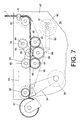
- FIG. 7 shows the side view of a belt spreading device 78 with up and down moving upper spreading rollers 79, 81 and stationary lower spreading rollers 80, 82.
- the opening device with the feed roller 16 is further in connection with Figure 2 described above.
- the sliver 1 passes a guide 5 and a deflecting roller 83 before it comes out of the upper Spreading roller 79 and the lower spreading roller 80 formed first spreading roller pair is supplied. Before it was the Feed roller 16 is submitted, it passes through a second the upper spreading roller 81 and the lower spreading roller 82 formed spreading roller pair.
- the height of the stationary lower spreading rollers 80, 82 is chosen so that Sliver 1 can run above the spreading rollers 80, 82, if there is between the deflection roller 83 and the feed roller 16 is pulled tight.
- the axes 84, 85 of the spreading rollers 79, 81 are on Angle lever 86 attached; the lower spreading rollers 80, 82 are mounted stationary on the housing 87.
- the storage corresponds to the Bearing of the spreading rollers 8, 10, 12 shown in Figure 2
- Angle lever 86 and the dashed line Swivel levers 88 are connected in a rotationally fixed manner to the shaft 89 and can be pivoted together about the axis of rotation of shaft 89.
- On The end of the pivot lever 88 is blown away by means of the crank rod 90 forth.
- the other end of the crank rod 90 engages the crank disk 91.
- the crank disc 91 is from Motor 92 driven.
- the speed of the crank disk 91 is between 500 revolutions per minute and 1,500 revolutions per minute Minute.
- the crank drive is a buffer element trained that when entering thickened tape or Belt twists no jam occurs.
- the lower spreading rollers 80, 82 are by means of Driving belt 93 via the intermediate gear 94 and the gear wheels 95, 96 rotated.
- the drive belt 93 also drives the Deflection roller 83.
- the gear ratios are like this chosen that both the deflection roller 83 and the Spreading rollers 79, 80, 81, 82 and the feed roller 16 die have the same peripheral speed.
- the sliver 1 loosens with each upward movement of the upper spreading rollers 79, 81 in the respective spreading roller pair the grooves.
- the new point of contact between fiber material and the webs is the downward movement of the Spreading rollers 79, 81 mostly shifted somewhat to the side.
- the Sliver 1 is not only more effective, but also spread more evenly.
Landscapes
- Engineering & Computer Science (AREA)
- Mechanical Engineering (AREA)
- Textile Engineering (AREA)
- Spinning Or Twisting Of Yarns (AREA)
- Preliminary Treatment Of Fibers (AREA)
- Nonwoven Fabrics (AREA)
Applications Claiming Priority (2)
| Application Number | Priority Date | Filing Date | Title |
|---|---|---|---|
| DE10135548 | 2001-07-20 | ||
| DE10135548A DE10135548A1 (de) | 2001-07-20 | 2001-07-20 | Offenend-Spinnvorrichtung |
Publications (3)
| Publication Number | Publication Date |
|---|---|
| EP1277859A2 true EP1277859A2 (fr) | 2003-01-22 |
| EP1277859A3 EP1277859A3 (fr) | 2003-05-28 |
| EP1277859B1 EP1277859B1 (fr) | 2005-09-14 |
Family
ID=7692607
Family Applications (1)
| Application Number | Title | Priority Date | Filing Date |
|---|---|---|---|
| EP02012279A Expired - Lifetime EP1277859B1 (fr) | 2001-07-20 | 2002-06-05 | Dispositif pour défibrer une mèche pour un métier à filer à bout libre |
Country Status (5)
| Country | Link |
|---|---|
| US (1) | US6796116B2 (fr) |
| EP (1) | EP1277859B1 (fr) |
| CN (1) | CN1399020A (fr) |
| CZ (1) | CZ20022296A3 (fr) |
| DE (2) | DE10135548A1 (fr) |
Cited By (1)
| Publication number | Priority date | Publication date | Assignee | Title |
|---|---|---|---|---|
| DE102009026737A1 (de) | 2008-09-16 | 2010-03-25 | Technische Universität Dresden | Vorrichtung und Verfahren zum Ausbreiten von bandförmigen Filamentgarnen |
Families Citing this family (5)
| Publication number | Priority date | Publication date | Assignee | Title |
|---|---|---|---|---|
| DE102005009731A1 (de) * | 2005-03-03 | 2006-09-07 | Rieter Ingolstadt Spinnereimaschinenbau Ag | Flyerloses Spinnverfahren sowie Vorrichtung mit einem Streckwerk |
| CH709566A1 (de) * | 2014-04-28 | 2015-10-30 | Rieter Ag Maschf | Abzugsanordnung für eine Spinnmaschine. |
| CZ306287B6 (cs) * | 2015-04-07 | 2016-11-16 | Rieter Cz S.R.O. | Způsob ukončení předení na pracovním místě rotorového dopřádacího stroje |
| CN106868658A (zh) * | 2017-03-22 | 2017-06-20 | 响水县晨丰纺织有限公司 | 一种摩擦纺纱机送纱机构 |
| CN113969442B (zh) * | 2021-10-29 | 2022-07-22 | 东台市兴源色织有限公司 | 一种棉布生产加工用转杯纺纱机 |
Family Cites Families (16)
| Publication number | Priority date | Publication date | Assignee | Title |
|---|---|---|---|---|
| US3107477A (en) * | 1949-11-23 | 1963-10-22 | Meimberg Julius | Process and apparatus for spinning fibrous materials |
| US3107447A (en) * | 1961-03-22 | 1963-10-22 | Anthony G Tucci | Seam-presser |
| GB1332856A (en) * | 1970-05-14 | 1973-10-10 | Chubu Seiko Kk | Rotary drafting apparatus |
| DE2506058C3 (de) * | 1975-02-13 | 1978-06-01 | Schubert & Salzer Maschinenfabrik Ag, 8070 Ingolstadt | Faserbandauflösevorrichtung für eine Offen-End-Spinnvorrichtung |
| US4369622A (en) * | 1980-03-24 | 1983-01-25 | Riegel Textile Corporation | Method and apparatus for drawing and blending textile materials |
| DE3219332A1 (de) * | 1982-05-22 | 1983-11-24 | F.A. Kümpers KG, 4440 Rheine | Lieferwalzen, die faserbaender kompakt erfassen und weiterfuehren |
| DE3245517C2 (de) * | 1982-12-09 | 1985-11-14 | Spinnbau GmbH, 2820 Bremen | Vorrichtung zum Verziehen von querorientiert einlaufenden Faservliesen |
| DE3402083C2 (de) * | 1984-01-21 | 1995-03-23 | Brockmanns Karl Josef Dr Ing | Verfahren und Vorrichtung zur Spinnfasernformation |
| DE3448514C2 (de) | 1984-01-21 | 1995-08-31 | Brockmanns Karl Josef Dr Ing | Faservorlageverstreckvorrichtung |
| CS264430B1 (en) * | 1987-06-15 | 1989-08-14 | Safar Vaclav | Device for fibres opening for spinning unit of spinning machine |
| US4979270A (en) * | 1989-08-03 | 1990-12-25 | Burlington Industries, Inc. | Apparatus and methods for converting tow into staple |
| DE4040102A1 (de) * | 1990-12-16 | 1992-06-17 | Fritz Stahlecker | Vorrichtung zum erspinnen eines fadens |
| US5699659A (en) * | 1996-03-08 | 1997-12-23 | Waverly Mills, Inc. | Process for producing substantially all-polyester yarns from fine denier feed fibers on an open end spinning machine |
| DE19610960A1 (de) * | 1996-03-20 | 1997-09-25 | Fritz Stahlecker | Verfahren zum Offenend-Spinnen |
| US6265045B1 (en) * | 1998-07-29 | 2001-07-24 | Clopay Plastic Products Company, Inc. | Method and apparatus for pin-hole prevention in zone laminates |
| US6368444B1 (en) * | 1998-11-17 | 2002-04-09 | Kimberly-Clark Worldwide, Inc. | Apparatus and method for cross-directional stretching of polymeric film and other nonwoven sheet material and materials produced therefrom |
-
2001
- 2001-07-20 DE DE10135548A patent/DE10135548A1/de not_active Withdrawn
-
2002
- 2002-06-05 EP EP02012279A patent/EP1277859B1/fr not_active Expired - Lifetime
- 2002-06-05 DE DE50204230T patent/DE50204230D1/de not_active Expired - Fee Related
- 2002-06-28 CZ CZ20022296A patent/CZ20022296A3/cs unknown
- 2002-07-19 US US10/199,824 patent/US6796116B2/en not_active Expired - Fee Related
- 2002-07-22 CN CN02126462A patent/CN1399020A/zh active Pending
Cited By (2)
| Publication number | Priority date | Publication date | Assignee | Title |
|---|---|---|---|---|
| DE102009026737A1 (de) | 2008-09-16 | 2010-03-25 | Technische Universität Dresden | Vorrichtung und Verfahren zum Ausbreiten von bandförmigen Filamentgarnen |
| DE102009026737B4 (de) * | 2008-09-16 | 2012-10-31 | Technische Universität Dresden | Vorrichtung und Verfahren zum Ausbreiten von bandförmigen Filamentgarnen |
Also Published As
| Publication number | Publication date |
|---|---|
| CN1399020A (zh) | 2003-02-26 |
| CZ20022296A3 (cs) | 2003-03-12 |
| DE50204230D1 (de) | 2005-10-20 |
| US20030014957A1 (en) | 2003-01-23 |
| DE10135548A1 (de) | 2003-01-30 |
| EP1277859B1 (fr) | 2005-09-14 |
| EP1277859A3 (fr) | 2003-05-28 |
| US6796116B2 (en) | 2004-09-28 |
Similar Documents
| Publication | Publication Date | Title |
|---|---|---|
| EP1984549B1 (fr) | Machine permettant de fabriquer des tissus maillés en matière fibreuse, en particulier métier à tricoter circulaire | |
| CH634883A5 (de) | Offen-end-friktionsspinnvorrichtung fuer eine spinneinheit. | |
| DE3878573T2 (de) | Vorrichtung und verfahren zum verstrecken textiler faserbaender. | |
| DE102009026737B4 (de) | Vorrichtung und Verfahren zum Ausbreiten von bandförmigen Filamentgarnen | |
| EP0165398A1 (fr) | Procédé et dispositif pour réaliser un fil par filature à friction | |
| EP0470949A2 (fr) | Dispositif pour le filage en continu de filaments | |
| EP1277859B1 (fr) | Dispositif pour défibrer une mèche pour un métier à filer à bout libre | |
| WO2015177227A1 (fr) | Machine à filer équipé d'un dispositif de fausse torsion | |
| EP3027794B1 (fr) | Métier à filer avec dispositif de fausse torsion | |
| EP0365856B1 (fr) | Dispositif de courroie transversal à la sortie d'une machine de cardage | |
| CH659837A5 (de) | Flachstrickmaschine mit einer vorrichtung zum abzug von formgestricken. | |
| EP2832904A1 (fr) | Métier à tisser et dispositif fausse-torsion | |
| DE602005006163T2 (de) | Kämmmaschine für Baumwolle und dergleichen mit verbesserter Vorrichtung zur Faserbandformung | |
| EP3027792B1 (fr) | Métier à filer avec dispositif de fausse torsion | |
| WO2007093164A1 (fr) | Procédé d'étirage et système d'étirage pour l'affinage de matière fibreuse | |
| DE3012929C2 (de) | Vorrichtung zum Herstellen eines aus mehreren Garnkomponenten bestehenden Effektfadens | |
| DE10051413A1 (de) | Spinnmaschine mit einer Verdichtungseinrichtung | |
| WO2015014682A1 (fr) | Métier à filer et dispositif de fausse torsion | |
| DE4003811A1 (de) | Riemchen-streckwerk sowie spinnmaschine mit einer vielzahl derartiger riemchen-streckwerke | |
| DE109147C (fr) | ||
| DE4004045A1 (de) | Vorrichtung zum pneumatischen falschdrallspinnen | |
| DE19615736A1 (de) | Vorrichtung zum Offenend-Spinnen | |
| DE3641177C2 (fr) | ||
| DE1510455C (de) | Nadelstabstrecke fur Faser bander | |
| DE19805396A1 (de) | Spinnmaschine mit Verdichtungseinrichtung |
Legal Events
| Date | Code | Title | Description |
|---|---|---|---|
| PUAI | Public reference made under article 153(3) epc to a published international application that has entered the european phase |
Free format text: ORIGINAL CODE: 0009012 |
|
| AK | Designated contracting states |
Kind code of ref document: A2 Designated state(s): AT BE CH CY DE DK ES FI FR GB GR IE IT LI LU MC NL PT SE TR |
|
| AX | Request for extension of the european patent |
Free format text: AL;LT;LV;MK;RO;SI |
|
| PUAL | Search report despatched |
Free format text: ORIGINAL CODE: 0009013 |
|
| AK | Designated contracting states |
Designated state(s): AT BE CH CY DE DK ES FI FR GB GR IE IT LI LU MC NL PT SE TR |
|
| AX | Request for extension of the european patent |
Extension state: AL LT LV MK RO SI |
|
| RIC1 | Information provided on ipc code assigned before grant |
Ipc: 7D 01H 5/00 B Ipc: 7D 01H 4/30 A |
|
| RAP1 | Party data changed (applicant data changed or rights of an application transferred) |
Owner name: SAURER GMBH & CO. KG |
|
| 17P | Request for examination filed |
Effective date: 20031128 |
|
| AKX | Designation fees paid |
Designated state(s): CH DE IT LI |
|
| GRAP | Despatch of communication of intention to grant a patent |
Free format text: ORIGINAL CODE: EPIDOSNIGR1 |
|
| GRAS | Grant fee paid |
Free format text: ORIGINAL CODE: EPIDOSNIGR3 |
|
| GRAA | (expected) grant |
Free format text: ORIGINAL CODE: 0009210 |
|
| AK | Designated contracting states |
Kind code of ref document: B1 Designated state(s): CH DE IT LI |
|
| REG | Reference to a national code |
Ref country code: CH Ref legal event code: EP |
|
| REF | Corresponds to: |
Ref document number: 50204230 Country of ref document: DE Date of ref document: 20051020 Kind code of ref document: P |
|
| PG25 | Lapsed in a contracting state [announced via postgrant information from national office to epo] |
Ref country code: LI Free format text: LAPSE BECAUSE OF NON-PAYMENT OF DUE FEES Effective date: 20060630 Ref country code: CH Free format text: LAPSE BECAUSE OF NON-PAYMENT OF DUE FEES Effective date: 20060630 |
|
| PGFP | Annual fee paid to national office [announced via postgrant information from national office to epo] |
Ref country code: IT Payment date: 20060630 Year of fee payment: 5 |
|
| PLBE | No opposition filed within time limit |
Free format text: ORIGINAL CODE: 0009261 |
|
| STAA | Information on the status of an ep patent application or granted ep patent |
Free format text: STATUS: NO OPPOSITION FILED WITHIN TIME LIMIT |
|
| 26N | No opposition filed |
Effective date: 20060615 |
|
| PG25 | Lapsed in a contracting state [announced via postgrant information from national office to epo] |
Ref country code: DE Free format text: LAPSE BECAUSE OF NON-PAYMENT OF DUE FEES Effective date: 20070103 |
|
| REG | Reference to a national code |
Ref country code: CH Ref legal event code: PL |
|
| PG25 | Lapsed in a contracting state [announced via postgrant information from national office to epo] |
Ref country code: IT Free format text: LAPSE BECAUSE OF NON-PAYMENT OF DUE FEES Effective date: 20070605 |