EP1281296B1 - Doppel-plasmabrennervorrichtung - Google Patents
Doppel-plasmabrennervorrichtung Download PDFInfo
- Publication number
- EP1281296B1 EP1281296B1 EP01966790A EP01966790A EP1281296B1 EP 1281296 B1 EP1281296 B1 EP 1281296B1 EP 01966790 A EP01966790 A EP 01966790A EP 01966790 A EP01966790 A EP 01966790A EP 1281296 B1 EP1281296 B1 EP 1281296B1
- Authority
- EP
- European Patent Office
- Prior art keywords
- gas
- plasma
- torch
- assembly
- feed material
- Prior art date
- Legal status (The legal status is an assumption and is not a legal conclusion. Google has not performed a legal analysis and makes no representation as to the accuracy of the status listed.)
- Expired - Lifetime
Links
- 239000000463 material Substances 0.000 claims abstract description 57
- 238000012545 processing Methods 0.000 claims abstract description 43
- 238000000429 assembly Methods 0.000 claims abstract description 13
- 230000000712 assembly Effects 0.000 claims abstract description 13
- 239000007789 gas Substances 0.000 claims description 93
- 239000000843 powder Substances 0.000 claims description 36
- 238000000034 method Methods 0.000 claims description 31
- 238000001816 cooling Methods 0.000 claims description 21
- 239000012530 fluid Substances 0.000 claims description 12
- 239000004411 aluminium Substances 0.000 claims description 9
- XAGFODPZIPBFFR-UHFFFAOYSA-N aluminium Chemical compound [Al] XAGFODPZIPBFFR-UHFFFAOYSA-N 0.000 claims description 9
- 229910052782 aluminium Inorganic materials 0.000 claims description 9
- XKRFYHLGVUSROY-UHFFFAOYSA-N Argon Chemical compound [Ar] XKRFYHLGVUSROY-UHFFFAOYSA-N 0.000 claims description 8
- 239000011261 inert gas Substances 0.000 claims description 7
- QVGXLLKOCUKJST-UHFFFAOYSA-N atomic oxygen Chemical compound [O] QVGXLLKOCUKJST-UHFFFAOYSA-N 0.000 claims description 6
- 239000001301 oxygen Substances 0.000 claims description 6
- 229910052760 oxygen Inorganic materials 0.000 claims description 6
- 239000002184 metal Substances 0.000 claims description 5
- 239000002245 particle Substances 0.000 claims description 5
- 239000000956 alloy Substances 0.000 claims description 4
- 229910052786 argon Inorganic materials 0.000 claims description 4
- 239000001307 helium Substances 0.000 claims description 4
- 229910052734 helium Inorganic materials 0.000 claims description 4
- SWQJXJOGLNCZEY-UHFFFAOYSA-N helium atom Chemical compound [He] SWQJXJOGLNCZEY-UHFFFAOYSA-N 0.000 claims description 4
- 229910052751 metal Inorganic materials 0.000 claims description 4
- 229910045601 alloy Inorganic materials 0.000 claims description 3
- 238000006243 chemical reaction Methods 0.000 claims description 3
- 239000000112 cooling gas Substances 0.000 claims description 3
- OKTJSMMVPCPJKN-UHFFFAOYSA-N Carbon Chemical compound [C] OKTJSMMVPCPJKN-UHFFFAOYSA-N 0.000 claims description 2
- 229910002804 graphite Inorganic materials 0.000 claims description 2
- 239000010439 graphite Substances 0.000 claims description 2
- 230000008878 coupling Effects 0.000 description 16
- 238000010168 coupling process Methods 0.000 description 16
- 238000005859 coupling reaction Methods 0.000 description 16
- 239000000615 nonconductor Substances 0.000 description 8
- PNEYBMLMFCGWSK-UHFFFAOYSA-N Alumina Chemical compound [O-2].[O-2].[O-2].[Al+3].[Al+3] PNEYBMLMFCGWSK-UHFFFAOYSA-N 0.000 description 6
- 239000007788 liquid Substances 0.000 description 6
- 238000004519 manufacturing process Methods 0.000 description 6
- 239000012809 cooling fluid Substances 0.000 description 5
- 238000010276 construction Methods 0.000 description 4
- 238000012986 modification Methods 0.000 description 4
- 230000004048 modification Effects 0.000 description 4
- 239000007787 solid Substances 0.000 description 4
- XLYOFNOQVPJJNP-UHFFFAOYSA-N water Substances O XLYOFNOQVPJJNP-UHFFFAOYSA-N 0.000 description 4
- QGZKDVFQNNGYKY-UHFFFAOYSA-N Ammonia Chemical compound N QGZKDVFQNNGYKY-UHFFFAOYSA-N 0.000 description 3
- 239000003570 air Substances 0.000 description 3
- 239000004744 fabric Substances 0.000 description 3
- 239000000047 product Substances 0.000 description 3
- 238000010791 quenching Methods 0.000 description 3
- 229910017083 AlN Inorganic materials 0.000 description 2
- PIGFYZPCRLYGLF-UHFFFAOYSA-N Aluminum nitride Chemical compound [Al]#N PIGFYZPCRLYGLF-UHFFFAOYSA-N 0.000 description 2
- IJGRMHOSHXDMSA-UHFFFAOYSA-N Atomic nitrogen Chemical compound N#N IJGRMHOSHXDMSA-UHFFFAOYSA-N 0.000 description 2
- 238000004458 analytical method Methods 0.000 description 2
- 239000012141 concentrate Substances 0.000 description 2
- 239000002826 coolant Substances 0.000 description 2
- 238000013461 design Methods 0.000 description 2
- VNWKTOKETHGBQD-UHFFFAOYSA-N methane Chemical compound C VNWKTOKETHGBQD-UHFFFAOYSA-N 0.000 description 2
- 239000000203 mixture Substances 0.000 description 2
- 239000002105 nanoparticle Substances 0.000 description 2
- 239000011858 nanopowder Substances 0.000 description 2
- 150000004767 nitrides Chemical class 0.000 description 2
- 239000004810 polytetrafluoroethylene Substances 0.000 description 2
- 229920001343 polytetrafluoroethylene Polymers 0.000 description 2
- 238000013341 scale-up Methods 0.000 description 2
- 229910052582 BN Inorganic materials 0.000 description 1
- PZNSFCLAULLKQX-UHFFFAOYSA-N Boron nitride Chemical compound N#B PZNSFCLAULLKQX-UHFFFAOYSA-N 0.000 description 1
- OTMSDBZUPAUEDD-UHFFFAOYSA-N Ethane Chemical compound CC OTMSDBZUPAUEDD-UHFFFAOYSA-N 0.000 description 1
- UFHFLCQGNIYNRP-UHFFFAOYSA-N Hydrogen Chemical compound [H][H] UFHFLCQGNIYNRP-UHFFFAOYSA-N 0.000 description 1
- 229910052581 Si3N4 Inorganic materials 0.000 description 1
- 229910021529 ammonia Inorganic materials 0.000 description 1
- 230000004888 barrier function Effects 0.000 description 1
- 230000015572 biosynthetic process Effects 0.000 description 1
- 239000002131 composite material Substances 0.000 description 1
- 230000003750 conditioning effect Effects 0.000 description 1
- 238000004320 controlled atmosphere Methods 0.000 description 1
- 239000000498 cooling water Substances 0.000 description 1
- 230000000593 degrading effect Effects 0.000 description 1
- 239000008367 deionised water Substances 0.000 description 1
- 238000011161 development Methods 0.000 description 1
- 230000007613 environmental effect Effects 0.000 description 1
- 238000005530 etching Methods 0.000 description 1
- 238000001704 evaporation Methods 0.000 description 1
- 230000008020 evaporation Effects 0.000 description 1
- 239000002803 fossil fuel Substances 0.000 description 1
- 238000010438 heat treatment Methods 0.000 description 1
- 239000003779 heat-resistant material Substances 0.000 description 1
- 239000001257 hydrogen Substances 0.000 description 1
- 229910052739 hydrogen Inorganic materials 0.000 description 1
- 230000002401 inhibitory effect Effects 0.000 description 1
- 150000002500 ions Chemical class 0.000 description 1
- 238000002844 melting Methods 0.000 description 1
- 230000008018 melting Effects 0.000 description 1
- 239000007769 metal material Substances 0.000 description 1
- 229910044991 metal oxide Inorganic materials 0.000 description 1
- 238000005121 nitriding Methods 0.000 description 1
- 229910052757 nitrogen Inorganic materials 0.000 description 1
- 229910000069 nitrogen hydride Inorganic materials 0.000 description 1
- 239000010815 organic waste Substances 0.000 description 1
- 230000003647 oxidation Effects 0.000 description 1
- 238000007254 oxidation reaction Methods 0.000 description 1
- 239000013618 particulate matter Substances 0.000 description 1
- 239000012254 powdered material Substances 0.000 description 1
- 239000002244 precipitate Substances 0.000 description 1
- 238000001556 precipitation Methods 0.000 description 1
- 230000002035 prolonged effect Effects 0.000 description 1
- 230000001681 protective effect Effects 0.000 description 1
- 238000000197 pyrolysis Methods 0.000 description 1
- 238000002407 reforming Methods 0.000 description 1
- 238000007789 sealing Methods 0.000 description 1
- HQVNEWCFYHHQES-UHFFFAOYSA-N silicon nitride Chemical compound N12[Si]34N5[Si]62N3[Si]51N64 HQVNEWCFYHHQES-UHFFFAOYSA-N 0.000 description 1
- 239000000126 substance Substances 0.000 description 1
- 238000003786 synthesis reaction Methods 0.000 description 1
- 238000007669 thermal treatment Methods 0.000 description 1
- 238000012546 transfer Methods 0.000 description 1
- 230000005068 transpiration Effects 0.000 description 1
- SANRKQGLYCLAFE-UHFFFAOYSA-H uranium hexafluoride Chemical compound F[U](F)(F)(F)(F)F SANRKQGLYCLAFE-UHFFFAOYSA-H 0.000 description 1
Images




Classifications
-
- H—ELECTRICITY
- H05—ELECTRIC TECHNIQUES NOT OTHERWISE PROVIDED FOR
- H05H—PLASMA TECHNIQUE; PRODUCTION OF ACCELERATED ELECTRICALLY-CHARGED PARTICLES OR OF NEUTRONS; PRODUCTION OR ACCELERATION OF NEUTRAL MOLECULAR OR ATOMIC BEAMS
- H05H1/00—Generating plasma; Handling plasma
- H05H1/24—Generating plasma
- H05H1/26—Plasma torches
-
- H—ELECTRICITY
- H05—ELECTRIC TECHNIQUES NOT OTHERWISE PROVIDED FOR
- H05H—PLASMA TECHNIQUE; PRODUCTION OF ACCELERATED ELECTRICALLY-CHARGED PARTICLES OR OF NEUTRONS; PRODUCTION OR ACCELERATION OF NEUTRAL MOLECULAR OR ATOMIC BEAMS
- H05H1/00—Generating plasma; Handling plasma
- H05H1/24—Generating plasma
- H05H1/26—Plasma torches
- H05H1/32—Plasma torches using an arc
- H05H1/44—Plasma torches using an arc using more than one torch
-
- Y—GENERAL TAGGING OF NEW TECHNOLOGICAL DEVELOPMENTS; GENERAL TAGGING OF CROSS-SECTIONAL TECHNOLOGIES SPANNING OVER SEVERAL SECTIONS OF THE IPC; TECHNICAL SUBJECTS COVERED BY FORMER USPC CROSS-REFERENCE ART COLLECTIONS [XRACs] AND DIGESTS
- Y10—TECHNICAL SUBJECTS COVERED BY FORMER USPC
- Y10S—TECHNICAL SUBJECTS COVERED BY FORMER USPC CROSS-REFERENCE ART COLLECTIONS [XRACs] AND DIGESTS
- Y10S977/00—Nanotechnology
- Y10S977/70—Nanostructure
- Y10S977/773—Nanoparticle, i.e. structure having three dimensions of 100 nm or less
- Y10S977/775—Nanosized powder or flake, e.g. nanosized catalyst
- Y10S977/777—Metallic powder or flake
-
- Y—GENERAL TAGGING OF NEW TECHNOLOGICAL DEVELOPMENTS; GENERAL TAGGING OF CROSS-SECTIONAL TECHNOLOGIES SPANNING OVER SEVERAL SECTIONS OF THE IPC; TECHNICAL SUBJECTS COVERED BY FORMER USPC CROSS-REFERENCE ART COLLECTIONS [XRACs] AND DIGESTS
- Y10—TECHNICAL SUBJECTS COVERED BY FORMER USPC
- Y10S—TECHNICAL SUBJECTS COVERED BY FORMER USPC CROSS-REFERENCE ART COLLECTIONS [XRACs] AND DIGESTS
- Y10S977/00—Nanotechnology
- Y10S977/84—Manufacture, treatment, or detection of nanostructure
- Y10S977/842—Manufacture, treatment, or detection of nanostructure for carbon nanotubes or fullerenes
- Y10S977/843—Gas phase catalytic growth, i.e. chemical vapor deposition
-
- Y—GENERAL TAGGING OF NEW TECHNOLOGICAL DEVELOPMENTS; GENERAL TAGGING OF CROSS-SECTIONAL TECHNOLOGIES SPANNING OVER SEVERAL SECTIONS OF THE IPC; TECHNICAL SUBJECTS COVERED BY FORMER USPC CROSS-REFERENCE ART COLLECTIONS [XRACs] AND DIGESTS
- Y10—TECHNICAL SUBJECTS COVERED BY FORMER USPC
- Y10S—TECHNICAL SUBJECTS COVERED BY FORMER USPC CROSS-REFERENCE ART COLLECTIONS [XRACs] AND DIGESTS
- Y10S977/00—Nanotechnology
- Y10S977/84—Manufacture, treatment, or detection of nanostructure
- Y10S977/842—Manufacture, treatment, or detection of nanostructure for carbon nanotubes or fullerenes
- Y10S977/844—Growth by vaporization or dissociation of carbon source using a high-energy heat source, e.g. electric arc, laser, plasma, e-beam
-
- Y—GENERAL TAGGING OF NEW TECHNOLOGICAL DEVELOPMENTS; GENERAL TAGGING OF CROSS-SECTIONAL TECHNOLOGIES SPANNING OVER SEVERAL SECTIONS OF THE IPC; TECHNICAL SUBJECTS COVERED BY FORMER USPC CROSS-REFERENCE ART COLLECTIONS [XRACs] AND DIGESTS
- Y10—TECHNICAL SUBJECTS COVERED BY FORMER USPC
- Y10S—TECHNICAL SUBJECTS COVERED BY FORMER USPC CROSS-REFERENCE ART COLLECTIONS [XRACs] AND DIGESTS
- Y10S977/00—Nanotechnology
- Y10S977/84—Manufacture, treatment, or detection of nanostructure
- Y10S977/90—Manufacture, treatment, or detection of nanostructure having step or means utilizing mechanical or thermal property, e.g. pressure, heat
Definitions
- the invention relates to a twin plasma torch apparatus.
- twin plasma torch apparatus In a twin plasma torch apparatus, the two torches are oppositely charged i.e. one has an anode electrode and the other a cathode electrode. In such apparatus, the arcs generated by each electrode are coupled together in a coupling zone remote from the two torches. Plasma gases are passed through each torch and are ionised to form a plasma which concentrates in the coupling zone, away from torch interference. Material to be heated/melted may be directed into this coupling zone wherein the thermal energy in the plasma is transferred to the material. Twin plasma processing can occur in open or confined processing zones.
- the twin arc process is energy efficient because as the resistance of the coupling between the two arcs increases remote from the two torches, the energy is increased but torch losses remain constant.
- the process is also advantageous in that relatively high temperatures are readily reached and maintained. This is attributable to both the fact that the energy from the two torches is combined and also because of the above mentioned efficiency.
- the torch nozzles project into the chamber so that the chamber walls, which have a low resistance, are removed from the vicinity of the plasma arc.
- This awkward construction inhibits side-arcing and encourages coupling of the arcs.
- the protruding nozzles provide surfaces on which melted material may precipitate. This not only results in wastage of material but shortens the life of the torches.
- additional fluid N 2 and/or NH 3
- the document emphasises the large scale of the chamber and similarly the extensive protrusion of torch nozzles into the internal reaction environment is observed.
- the torches are physically separate from the main chamber, they have environmental seals at their entry points and are electrically isolated.
- the present invention provides a twin plasma torch assembly comprising:
- the shroud gas confines the plasma gas, inhibits side-arcing, and increases plasma density.
- the invention therefore provides an assembly in which the torches are inhibited from side-arcing, and thus facilitates the miniaturisation of torch design where distance to low resistance paths are small.
- the use of shroud gas also eliminates the need for torch nozzles to extend beyond the housing.
- the shroud gas may be provided at various locations along the electrodes, particularly in cylindrical torches where arcs are generated along the length of the electrodes.
- each torch has a distal end for the discharge of plasma gas and the means for supplying shroud gas provides shroud gas downstream of the distal end of each electrode. Therefore, reactive gases such as oxygen may be added to the plasma without degrading the electrode.
- reactive gases such as oxygen may be added to the plasma without degrading the electrode.
- the practical applicability of plasma torches is increased by the facility to add reactive gases downstream of the electrode.
- each plasma torch comprises a housing which surrounds the electrode to define a shroud gas supply duct between the housing and the electrodes, wherein the end of the housing is tapered inwards towards the distal end of the torch to direct flow of the shroud gas around the plasma gas.
- the twin plasma torch assembly of the present invention may be used in an arc reactor having a chamber to carry out a plasma evaporation process to produce ultra-fine (i.e. sub-micron or nano-sized) powders, for example aluminium powders.
- the reactor may also be used in a spherodisation process.
- the chamber will typically have an elongate or tubular form with a plurality of orifices in a wall portion thereof, a twin plasma torch assembly being mounted over each orifice.
- the orifices, and thus the twin plasma torch assemblies, may be provided along and/or around said tubular portion.
- the orifices are preferably provided at substantially regular intervals.
- the distal ends of the first and/or second electrodes, for the discharge of plasma gas will typically be formed from a metallic material, but may also be formed from graphite.
- the plasma arc reactor preferably further comprises cooling means for cooling and condensing material which has been vaporised in the processing zone.
- the cooling means comprises a source of a cooling gas or a cooling ring.
- the plasma arc reactor will typically further comprise a collection zone for collecting processed feed material.
- the process feed material will typically be in the form of a powder, liquid or gas.
- the collection zone may be provided downstream of the cooling zone for collecting a powder of the condensed vaporised material.
- the collection zone may comprise a filter cloth which separates the powder particulate from the gas stream.
- the filter cloth is preferably mounted on an earthed cage to prevent electrostatic charge build up.
- the powder may then be collected from the filter cloth, preferably in a controlled atmosphere zone.
- the resulting powder product is preferably then sealed, in inert gas, in a container at a pressure above atmospheric pressure.
- the plasma arc reactor may further comprise means to transport processed feed material to the collection zone.
- Such means may be provided by a flow of fluid, such as, for example, an inert gas, through the chamber, wherein, in use, processed feed material is entrained in the fluid flow and is thereby transported to the collection zone.
- the means for generating a plasma arc in the space between the first and second electrodes will generally comprise a DC or AC power source.
- the apparatus according to the present invention may operate without using any water-cooled elements inside the plasma reactor and allows replenishment of feed material without stopping the reactor.
- the means for supplying feed material into the processing zone may be achieved by providing a material feed tube which is integrated with the chamber and/or the twin torch assembly.
- the material may be particulate matter such as a metal or may be a gas such as air, oxygen or hydrogen or steam to increase the power at which the torch assembly operates.
- first and second electrodes for the discharge of plasma gas, do not project into the chamber.
- the small size of the compact twin torch arrangement according to the present invention allows many units to be installed onto a product transfer tube. This enables easy scale-up to typically over 10 times to give a full production unit without scale up uncertainty.
- the present invention also provides a process for producing a powder from a feed material, which process comprises:
- the feed material will generally comprise or consist of a metal, for example aluminium or an alloy thereof. However, liquid and/or gaseous feed materials can also be used.
- the material may be provided in any suitable form which allows it to be fed into the space between the electrodes, i.e, into the processing zone.
- the material may be in the form of a wire, fibres and/or a particulate.
- the plasma gas will generally comprise or consist of an inert gas, for example helium and/or argon.
- the plasma gas is advantageously injected into the space between the first and second electrodes, i.e. the processing zone.
- At least some cooling of the vaporised material may be achieved using an inert gas stream, for example argon and/or helium.
- a reactive gas stream may be used.
- the use of a reactive gas enables oxide and nitride powders to be produced.
- oxide powders such as aluminium oxide powders.
- a reactive gas comprising, for example, ammonia can result in the production of nitride powders, such as aluminium nitride powders.
- the cooling gas may be recycled via a water-cooled conditioning chamber.
- the surface of the powder may be oxidised using a passivating gas stream. This is particularly advantageous when the material is a reactive metal, such as aluminium or is aluminium-based.
- the passivating gas may comprise an oxygen-containing gas.
- processing conditions such as material and gas feed rates, temperature and pressure, will need to be tailored to the particular material to be processed and the desired size of the particles in the final powder.
- the reactor may be preheated to a temperature of at least about 2000°C and typically approximately 2200°C. Preheating may be achieved using a plasma arc.
- the rate at which the solid feed material is fed into the channel in the first electrode will affect the product yield and powder size.
- the process according to the present invention may be used to produce a powdered material having a composition based on a mixture of aluminium metal and aluminium oxide. This is thought to arise with the oxygen addition made to the material during processing under low temperature oxidation conditions.
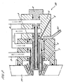
- Figures 1 and 2 are cross sections of assembled cathode 10 and anode 20 torch assemblies respectively. These are of modular construction each comprising an electrode module 1 or 2, a nozzle module 3, a shroud module 4, and a electrode guide module 5.
- the electrode module 1, 2 is in the interior of the torch 10, 20.
- the electrode guide module 5 and the nozzle module 3 are axially spaced apart surrounded the electrode module 1,2 at locations along its length. At least the distal end (i.e. the end from which plasma is discharged from the torch) of the electrode module 1, 2 is surrounded by the nozzle module 3.
- the proximal end of the electrode module 1 or 2 is housed in the electrode guide module 5.
- the nozzle module 3 is housed in the shroud module 4.
- O rings Sealing between the various modules and also the module elements is provided by “O” rings.
- O provide seals between the nozzle module 3 and both the shroud module 4 and electrode guide module 5.
- "O" rings are shown as small filled circles within a chamber.
- Each torch 10, 20 has ports 51 and 44 for entry of process gas and shroud gas respectively. Entry of process gas is towards the proximal end of the torch 10, 20.
- Process gas enters a passage 53 between the electrode 1 or 2 and the nozzle 3 and travels towards the distal end of the torch 10, 20.
- shroud gas is provided at the distal end of the torch 10, 20. This keeps shroud gas away from the electrode and is particularly advantageous when using a shroud gas which may degrade the electrode modules 1, 2, e.g. oxygen.
- the shroud gas could enter towards the proximal end of the torch 10, 20.
- the shroud module 4 is fitted at the distal end of the torch 10, 20.
- the shroud module 4 comprises a nozzle guide 41, a shroud gas guide 42, an electrical insulator 43, a chamber wall 111, and also a seat 46.
- An "O" ring is provided to seal the chamber wall 111 and the nozzle guide 41.
- coolant fluid may also be transported within the chamber wall 111.
- the electrical insulator 43 is located on the chamber wall 111 such that there is no low resistance path at the distal end of the torch to facilitate arc destabilisation.
- the electrical insulator 43 is typically made of boron nitride or silicon nitride.
- the shroud gas guide 42 is located on the electrical insulator 43 and provides support for the distal end of the nozzle module 3 and also allows flow of shroud gas out of the distal end of the torch. It is typically made from PTFE.
- the nozzle guide 41 is made of an electrical insulator, such as PTFE, and is used to locate the nozzle module 3 in the shroud module 4.
- the nozzle guide 41 also contains a passage 44 through which shroud gas is fed to an chamber 47.
- Shroud gas exits from the chamber 47 through passages 45 located in the shroud gas guide 42. These passages 45 are along the contact edge with the electrical insulator 43.
- shroud gas is shown to be delivered to the torch 10, 20 using a specific arrangement for the shroud gas module 4 ( Figure 8), delivery may be by other means.
- shroud gas may be delivered near the proximal end of the torch, through a passage surrounding the process gas passage 51.
- the shroud gas may also be delivered to an annular ring located at and offset from the distal end of the torch.
- the electrode guide module 5 conveniently provides a passage or port 51 for the entry of process gas.
- the internal proximal end of the nozzle module 3 is advantageously chamfered to direct flow of process gas from the passage 51 into the nozzle module 3 and around the electrode.
- the electrode guide module 5 needs to be correctly circumferentially aligned such that the electrode guide cooling circuit and the torch cooling circuit (discussed below) align.
- the nozzle module 3 and electrode modules 1 and 2 have cooling channels for the circulation of cooling fluid.
- the cooling circuits are combined into a single circuit in which cooling fluid enters the torch through an single torch entry port 8 and exits torch out of a single torch exit port 9.
- the cooling fluid enters through the entry port 8 travels through the electrode module 1, 2 to the nozzle module 3, and then exits out of the torch through a nozzle exit port 9.
- the fluid which leaves the nozzle exit port 9 is transported to a heat exchanger to provide cooled fluid which is recirculated to the entry port 8.
- fluid entering from the torch entry port 8 is directed to an electrode entry port 81. Cooling fluid enters the electrode near its proximal end and travels along a central passage to the distal end wherein it is redirected back to flow along a surrounding outer passage (or number of passages) and out of an electrode exit port 91. This fluid enters the nozzle at entry port 82 and flows along interior passages to the distal end of the nozzle. It is then directed back along surrounding passages to the exit from the nozzle port 92. The fluid is directed to the torch exit port 9.
- any fluid which acts as an effective coolant may be used in the cooling circuit.
- the water should preferably be de-ionised water to provide a high resistance path to current flow.
- the torches 10 and 20 may be used for twin plasma torch assemblies, in both open and confined processing zone chambers.
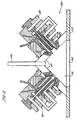
- the construction of confined processing zone twin plasma torch assembly 100 is shown in Figure 9.
- the assembly 100 is configured to provide torches 10, 20 which are easily installed to the correct position for operation.
- the offset between the distal ends of the electrodes 1, 2 and the angle between them are determined by the dimensions of the assembly components.
- the torch and assembly modules are constructed to close tolerance to provide good fitting between the modules. This would limit radial movement of one module within another module. To allow ease of assembly and re-assembly, corresponding modules would slide into one another and be locked in by for example, locking pins. The use of locking pins in the modules would also ensure that each module was correctly oriented within the torch assemblies ie. provide circumferential registration.
- the confined processing zone twin torch assembly 100 comprises a cathode and anode torch assemblies 10 and 20, and a feed tube 112. Typically, the two torches are at right angles to one another. The components are arranged to provide a confined processing zone 110 in which coupling of the arcs will occur.
- the feed tube 112 is used to supply powder, liquid, or gas feed material into the processing zone 110.
- the walls 111 of the shroud modules 4 conveniently define the chamber which contains the confined processing zone 110.
- the walls 111 provide a divergent processing zone 110 in which the low resistance wall surfaces are maintained away from the arcs, inhibiting side-arcing.
- the divergent nature of the design allows gas expansion after plasma coupling, without a constrictive pressure build-up.
- the walls 111 define a conical chamber which may comprise curved or flat walls.
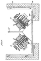
- the perimeter of the walls 111 may be joined to chamber walls 113 to enable the assembly 100 to be mounted ( Figure 4).
- a circular orifice 114 can have a diameter of 15cm.
- the confined processing zone 110 may be made as a separate module comprising the feed tube 112, and the chamber walls 111 and 113.
- the assembly 100 may be mounted into a cylinder which comprises (optional) inner cooling walls 115, surrounded by an outer refractory lining 116 ( Figure 4).
- the lining 116 would preferably be a heat resistant material.
- the walls 111 may themselves also have integrated cooling channels.
- a shroud gas is provided to encircle the arcs generated from the electrodes.
- the shroud gas may be helium, nitrogen or air. Any gas which provides a high resistance path to prevent the arc from travelling through the shroud is suitable. Preferably, the gas should be relatively cold.
- the high resistance path of the shroud gas concentrates the arc into a relatively narrow bandwidth.
- the tapered distal end of the nozzle module assists in providing a gas shroud which is directed to encircle the arc.
- the shroud gas also acts to confine the plasma and inhibits melted feed material from being recirculated back towards the feed tube 112 or the chamber walls 111. Thus, the efficiency of processing is increased.
- any regions of the assembly which are particularly close to the arcs are made or coated with an electrical insulator, for example the shroud gas guide 42 and the electrical insulator 43.
- the invention may be applied to numerous practical applications, for example to manufacture nano-powders, spherodisation of powders or the treatment of organic waste. Some further examples are given below.
- the invention allows replacement of existing gas fossil fuel burners with an electrical gas heater. Introducing water between the two torches will enable steam to be generated which may be used to heat existing kilns and incinerators. Gasses may be introduced between the arcs to give an efficient gas heater.
- Materials which dissociate into chemically reactive materials may be processed in the unit as there need not be any reactor wall contact at high temperatures.
- the walls 111 of the water cooled processing zone chamber would have a grated surface to allow transpiration to occur. This creates a protective barrier to stop reactive gas impingement.
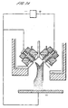
- the assembly may be utilised to produce ultra fine powders (generally of unit dimension of less than 200 nanometres) is illustrated in Figure 5.
- the small size of the unit enables easy attachment of a quench ring 130 in close proximity to the gaseous high temperature plasma coupling zone. Fine powder is produced in the zone 132, within the expansion zone 131. Higher gas quench velocities produce smaller the terminal unit dimension of the particles.
- a plurality of twin torch assemblies as herein described may be mounted on a processing chamber.
- nano-powders produced by this method would produce finer powders as it would be possible to install the quench apparatus 130 in close proximity to the arc to arc coupling zone. This would minimise the time available for the powder/liquid feed material particles to grow.
- composite materials may be fed to make nano-alloy materials.
- the modular assembly may also be configured as to operate in transferred arc modes with anode ( Figure 6) and cathode ( Figure 7) targets.
- the torches described above are suitable for operation in transferred arc to arc coupling mode ( Figures 6A and 7A) and transferred arc mode ( Figures 6B and 7B).
- Typical plasma gas temperatures at the arc to arc coupling zone have been measured to be up to 10,000 K for an Argon plasma. Introduction of angular particles results in spherodisation.
- the Coupling zone between the arcs may be used to thermally modify a feed gas, for example methane, ethane or UF6.
- the plasma plume may also be used to achieve surface modification by, for example, ion impingement, melting, or to chemically alter the surface such as in nitriding.
- the assembly according to the present invention may also be used in ICP analyses and as a high energy UV light source.
- cooling water systems of the two torches may be combined, or one or both of the torches of the twin apparatus could have a gas shroud.
- the gas shroud may be applied to torches which do not have the modular construction mentioned above.
- the apex cone angle in the torch assembly may be different for different applications. In some cases it may be desirable to fit to a cylinder without a cone.
- a plurality of twin torch assemblies as herein described may be mounted on chamber.
Landscapes
- Physics & Mathematics (AREA)
- Engineering & Computer Science (AREA)
- Plasma & Fusion (AREA)
- Spectroscopy & Molecular Physics (AREA)
- Physical Or Chemical Processes And Apparatus (AREA)
- Plasma Technology (AREA)
- Treatment Of Fiber Materials (AREA)
- Manufacture Of Metal Powder And Suspensions Thereof (AREA)
- Powder Metallurgy (AREA)
- Solid-Phase Diffusion Into Metallic Material Surfaces (AREA)
- Nozzles (AREA)
- Fuel Cell (AREA)
Claims (26)
- Doppelplasmabrenneranordnung, umfassend:dadurch gekennzeichnet, dass die distalen Enden der ersten und der zweiten Elektrode nicht über das Gehäuse hinaus vorstehen.(a) wenigstens zwei Plasmabrenneranordnungen entgegengesetzter Polarität, welche in einem Gehäuse gelagert sind, wobei die Anordnungen mit Abstand voneinander angeordnet sind und umfassen:(i) eine erste Elektrode (1) in einer ersten Brenneranordnung,(ii) eine zweite Elektrode (2) in einem zweiten Brenner, welche mit einem Abstand von der ersten Elektrode angeordnet ist oder dazu ausgebildet ist, mit einem Abstand von der ersten Elektrode angeordnet zu sein, der ausreichend ist, um zwischen diesen in einer Bearbeitungszone einen Plasmabogen zu erzielen;(b) Mittel (51, 53) zur Einleitung eines Plasmagases in die Bearbeitungszone um jede Elektrode herum;(c) Mittel (42, 44) zur Einleitung eines Schutzgases, um das Plasmagas zu umgeben;(d) Mittel (112) zum Zuführen von Zufuhrmaterial in die Bearbeitungszone; und(e) Mittel zur Erzeugung eines Plasmabogens in der Bearbeitungszone;
- Doppelplasmabrenneranordnung nach Anspruch 1, bei welcher jeder Brenner ein distales Ende zum Auslass von Plasmagas aufweist, wobei das Mittel (42, 44) zum Zuführen von Schutzgas ein Schutzgas stromabwärts des distalen Endes einer jeden Elektrode bereitstellt.
- Doppelplasmabrenneranordnung nach Anspruch 2, bei welcher jeder Brenner ein Gehäuse umfasst, das die Elektrode umgibt, um den Schutzgaszufuhrkanal zwischen dem Gehäuse und der Elektrode zu definieren, und bei welcher das Ende des Gehäuses nach innen zum distalen Ende des Brenners hin verjüngt ist, um eine Strömung des Schutzgases um das Plasmagas herum zu richten.
- Anordnung nach einem der vorhergehenden Ansprüche, welche ferner eine Sammelzone zum Sammeln von bearbeitetem Zufuhrmaterial in der Form eines Pulvers umfasst.
- Anordnung nach Anspruch 4, welche ferner Mittel zum Transportieren von bearbeitetem Zufuhrmaterial zur Sammelzone umfasst.
- Anordnung nach Anspruch 5, bei welcher das Mittel zum Transport von bearbeitetem Zufuhrmaterial zu der Sammelzone ein Mittel zur Bereitstellung einer Strömung von Fluid durch die Kammer hindurch umfasst, wobei im Betrieb bearbeitetes Zufuhrmaterial in der Fluidströmung mitgenommen wird und dadurch zur Sammelzone transportiert wird.
- Anordnung nach einem der vorhergehenden Ansprüche, bei welcher distale Enden der ersten und/oder der zweiten Elektrode (1, 2) zum Auslass von Plasmagas aus Graphit gebildet ist/sind.
- Anordnung nach einem der vorhergehenden Ansprüche, welche ferner ein Kühlmittel (130) zur Kühlung und Kondensation von Material umfasst, das in der Bearbeitungszone verdampft wurde.
- Anordnung nach Anspruch 8, bei welcher das Kühlmittel eine Kühlgasquelle oder einen Kühlring (130) umfasst.
- Anordnung nach einem der vorhergehenden Ansprüche, bei welcher das Mittel zur Erzeugung eines Plasmabogens in der Bearbeitungszone zwischen der ersten und der zweiten Elektrode (1, 2) eine Gleichstromoder Wechselstrom-Energiequelle umfasst.
- Plasmabogenreaktor, umfassend eine Kombination aus einer Reaktionskammer und einer Doppelplasmabrenneranordnung gemäß einem der vorhergehenden Ansprüche.
- Reaktor nach Anspruch 11, bei welchem die Kammer eine längliche Form mit einer Mehrzahl von Öffnungen in einem Wandabschnitt derselben aufweist; sowie eine Doppelplasmabrenneranordnung nach einem der vorhergehenden Ansprüche über jeder Öffnung montiert aufweist.
- Reaktor nach Anspruch 12, bei welchem die Kammer einen rohrförmigen Abschnitt mit einer Mehrzahl von Öffnungen in einem Wandabschnitt desselben aufweist, wobei eine Doppelplasmabrenneranordnung über jeder Öffnung montiert ist.
- Reaktor nach Anspruch 13, bei welchem die Öffnungen entlang des und/oder um den rohrförmigen Abschnitt herum vorgesehen sind.
- Reaktor nach einem der Ansprüche 12 bis 14, bei welchem die Öffnungen bei im Wesentlichen regelmäßigen Intervallen vorgesehen sind.
- Verfahren zur Erzeugung eines Pulvers aus einem Zufuhrmaterial, welches Verfahren umfasst:(A) Bereitstellen eines Plasmabogenreaktors, wie er in einem der Ansprüche 11 bis 15 definiert ist;(B) Einleiten eines Plasmagases in die Bearbeitungszonen zwischen der ersten und der zweiten Elektrode (1, 2);(C) Erzeugen eines Plasmabogens in den Bearbeitungszonen zwischen den ersten und den zweiten Elektroden;(D) Zuführen von Zufuhrmaterial in die Plasmabögen, wodurch das Zufuhrmaterial verdampft wird;(E) Kühlen des verdampften Materials, um ein Pulver zu kondensieren; und(F) Sammeln des Pulvers.
- Verfahren nach Anspruch 16, bei welchem das Zufuhrmaterial ein Metall oder eine Legierung umfasst oder aus einem Metall oder einer Legierung besteht.
- Verfahren nach Anspruch 17, bei welchem das Zufuhrmaterial Aluminium oder eine Legierung desselben ist.
- Verfahren nach einem der Ansprüche 16 bis 18, bei welchem das Zufuhrmaterial draht-, faser- und/oder teilchenförmig vorliegt.
- Verfahren nach einem der Ansprüche 16 bis 19, bei welchem das Plasmagas ein Inertgas umfasst oder aus einem Inertgas besteht.
- Prozess nach Anspruch 20, bei welchem das Plasmagas Helium und/oder Argon umfasst oder aus Helium und/oder Argon besteht.
- Verfahren nach einem der Ansprüche 16 bis 21, bei welchem das verdampfte Material unter Verwendung eines Intertgasstroms wenigstens etwas gekühlt wird.
- Verfahren nach einem der Ansprüche 16 bis 22, bei welchem das verdampfte Material unter Verwendung eines Reaktionsgasstroms wenigstens etwas gekühlt wird.
- Prozess nach einem der Ansprüche 16 bis 22, bei welchem die Oberfläche des Pulvers unter Verwendung eines Passivierungsgasstroms oxidiert wird.
- Prozess nach Anspruch 24, bei welchem das Passivierungsgas ein sauerstoffhaltiges Gas umfasst.
- Prozess nach einem der Ansprüche 16 bis 25, bei welchem das Pulver Partikel umfasst, von denen im Wesentlichen alle einen Durchmesser von weniger als 200 nm, vorzugsweise weniger als 50 nm aufweisen.
Applications Claiming Priority (5)
| Application Number | Priority Date | Filing Date | Title |
|---|---|---|---|
| GB0008797 | 2000-04-10 | ||
| GB0008797A GB0008797D0 (en) | 2000-04-10 | 2000-04-10 | Plasma torches |
| GB0022986A GB0022986D0 (en) | 2000-09-19 | 2000-09-19 | Plasma torches |
| GB0022986 | 2000-09-19 | ||
| PCT/GB2001/001545 WO2001078471A1 (en) | 2000-04-10 | 2001-04-04 | Twin plasma torch apparatus |
Publications (2)
| Publication Number | Publication Date |
|---|---|
| EP1281296A1 EP1281296A1 (de) | 2003-02-05 |
| EP1281296B1 true EP1281296B1 (de) | 2004-09-29 |
Family
ID=26244073
Family Applications (1)
| Application Number | Title | Priority Date | Filing Date |
|---|---|---|---|
| EP01966790A Expired - Lifetime EP1281296B1 (de) | 2000-04-10 | 2001-04-04 | Doppel-plasmabrennervorrichtung |
Country Status (12)
| Country | Link |
|---|---|
| US (1) | US6744006B2 (de) |
| EP (1) | EP1281296B1 (de) |
| JP (1) | JP5241984B2 (de) |
| KR (1) | KR100776068B1 (de) |
| CN (1) | CN1217561C (de) |
| AT (1) | ATE278314T1 (de) |
| AU (1) | AU9335001A (de) |
| CA (1) | CA2405743C (de) |
| DE (1) | DE60201387T2 (de) |
| IL (2) | IL152119A0 (de) |
| RU (1) | RU2267239C2 (de) |
| WO (1) | WO2001078471A1 (de) |
Families Citing this family (63)
| Publication number | Priority date | Publication date | Assignee | Title |
|---|---|---|---|---|
| US7576296B2 (en) | 1995-03-14 | 2009-08-18 | Battelle Energy Alliance, Llc | Thermal synthesis apparatus |
| US6395197B1 (en) | 1999-12-21 | 2002-05-28 | Bechtel Bwxt Idaho Llc | Hydrogen and elemental carbon production from natural gas and other hydrocarbons |
| JP2003522299A (ja) * | 2000-02-10 | 2003-07-22 | テトロニクス リミテッド | 微細粉末を製造するためのプラズマアーク反応器 |
| US20050195966A1 (en) * | 2004-03-03 | 2005-09-08 | Sigma Dynamics, Inc. | Method and apparatus for optimizing the results produced by a prediction model |
| EP1637325A1 (de) | 2004-09-16 | 2006-03-22 | Imperial Tobacco Limited | Verfahren zum Drucken einer Verpackungshülle eines Rauchartikels |
| US7763823B2 (en) * | 2004-10-29 | 2010-07-27 | United Technologies Corporation | Method and apparatus for microplasma spray coating a portion of a compressor blade in a gas turbine engine |
| IL168286A (en) * | 2005-04-28 | 2009-09-22 | E E R Env Energy Resrc Israel | Plasma torch for use in a waste processing chamber |
| US7342197B2 (en) * | 2005-09-30 | 2008-03-11 | Phoenix Solutions Co. | Plasma torch with corrosive protected collimator |
| US9681529B1 (en) * | 2006-01-06 | 2017-06-13 | The United States Of America As Represented By The Secretary Of The Air Force | Microwave adapting plasma torch module |
| FR2897747B1 (fr) | 2006-02-23 | 2008-09-19 | Commissariat Energie Atomique | Torche a plasma a arc transfere |
| US7671294B2 (en) * | 2006-11-28 | 2010-03-02 | Vladimir Belashchenko | Plasma apparatus and system |
| US9173967B1 (en) | 2007-05-11 | 2015-11-03 | SDCmaterials, Inc. | System for and method of processing soft tissue and skin with fluids using temperature and pressure changes |
| US9994450B2 (en) * | 2007-07-06 | 2018-06-12 | Evaco, Llc | Method and apparatus for a low cost and carbon free point of use dissociation of water into elemental gases and production of hydrogen related power |
| AU2012202058B2 (en) * | 2007-07-06 | 2015-05-28 | Evaco, Llc | Carbon free dissociation of water and production of hydrogen related power |
| US8507401B1 (en) | 2007-10-15 | 2013-08-13 | SDCmaterials, Inc. | Method and system for forming plug and play metal catalysts |
| WO2010142004A2 (en) | 2009-06-10 | 2010-12-16 | Katholieke Universifeit Leuven | Controlled biosecure aquatic farming system in a confined environment |
| US9126191B2 (en) | 2009-12-15 | 2015-09-08 | SDCmaterials, Inc. | Advanced catalysts for automotive applications |
| US8652992B2 (en) | 2009-12-15 | 2014-02-18 | SDCmaterials, Inc. | Pinning and affixing nano-active material |
| US8557727B2 (en) | 2009-12-15 | 2013-10-15 | SDCmaterials, Inc. | Method of forming a catalyst with inhibited mobility of nano-active material |
| US8803025B2 (en) * | 2009-12-15 | 2014-08-12 | SDCmaterials, Inc. | Non-plugging D.C. plasma gun |
| US9039916B1 (en) | 2009-12-15 | 2015-05-26 | SDCmaterials, Inc. | In situ oxide removal, dispersal and drying for copper copper-oxide |
| US9149797B2 (en) | 2009-12-15 | 2015-10-06 | SDCmaterials, Inc. | Catalyst production method and system |
| KR101581046B1 (ko) * | 2009-12-16 | 2015-12-30 | 주식회사 케이씨씨 | 플라즈마 아크토치의 위치조절장치 |
| JP2011140032A (ja) * | 2010-01-06 | 2011-07-21 | Honda Motor Co Ltd | 2電極アーク溶接装置及び2電極アーク溶接方法 |
| US8669202B2 (en) | 2011-02-23 | 2014-03-11 | SDCmaterials, Inc. | Wet chemical and plasma methods of forming stable PtPd catalysts |
| CN103635273A (zh) * | 2011-05-18 | 2014-03-12 | 东北泰克诺亚奇股份有限公司 | 金属粉末的制造方法及金属粉末的制造装置 |
| BR112014003781A2 (pt) | 2011-08-19 | 2017-03-21 | Sdcmaterials Inc | substratos revestidos para uso em catalisadores e conversores catalíticos e métodos para revestir substratos com composições de revestimento por imersão |
| US10314155B2 (en) * | 2012-08-06 | 2019-06-04 | Hypertherm, Inc. | Asymmetric consumables for a plasma arc torch |
| US9107282B2 (en) * | 2012-08-06 | 2015-08-11 | Hypertherm, Inc. | Asymmetric consumables for a plasma arc torch |
| US9497845B2 (en) | 2012-08-06 | 2016-11-15 | Hypertherm, Inc. | Consumables for a plasma arc torch for bevel cutting |
| US9781818B2 (en) | 2012-08-06 | 2017-10-03 | Hypertherm, Inc. | Asymmetric consumables for a plasma arc torch |
| US10721812B2 (en) | 2012-08-06 | 2020-07-21 | Hypertherm, Inc. | Asymmetric consumables for a plasma arc torch |
| US9095829B2 (en) * | 2012-08-16 | 2015-08-04 | Alter Nrg Corp. | Plasma fired feed nozzle |
| US9511352B2 (en) | 2012-11-21 | 2016-12-06 | SDCmaterials, Inc. | Three-way catalytic converter using nanoparticles |
| US9156025B2 (en) | 2012-11-21 | 2015-10-13 | SDCmaterials, Inc. | Three-way catalytic converter using nanoparticles |
| SK500582012A3 (sk) | 2012-12-17 | 2014-08-05 | Ga Drilling, A. S. | Multimodálne rozrušovanie horniny termickým účinkom a systém na jeho vykonávanie |
| US9987703B2 (en) * | 2012-12-17 | 2018-06-05 | Fuji Engineering Co., Ltd. | Plasma spraying apparatus |
| SK500062013A3 (sk) | 2013-03-05 | 2014-10-03 | Ga Drilling, A. S. | Generovanie elektrického oblúka, ktorý priamo plošne tepelne a mechanicky pôsobí na materiál a zariadenie na generovanie elektrického oblúka |
| DE102013103508A1 (de) * | 2013-04-09 | 2014-10-09 | PLASMEQ GmbH | Plasmabrenner |
| US9586179B2 (en) | 2013-07-25 | 2017-03-07 | SDCmaterials, Inc. | Washcoats and coated substrates for catalytic converters and methods of making and using same |
| CN106061600A (zh) | 2013-10-22 | 2016-10-26 | Sdc材料公司 | 用于重型柴油机的催化剂设计 |
| MX2016004759A (es) | 2013-10-22 | 2016-07-26 | Sdcmaterials Inc | Composiciones para trampas de oxidos de nitrogeno (nox) pobres. |
| US9687811B2 (en) | 2014-03-21 | 2017-06-27 | SDCmaterials, Inc. | Compositions for passive NOx adsorption (PNA) systems and methods of making and using same |
| CN105338724A (zh) * | 2014-08-14 | 2016-02-17 | 新疆兵团现代绿色氯碱化工工程研究中心(有限公司) | 一种v型等离子体炬的喷口 |
| DE102014219275A1 (de) | 2014-09-24 | 2016-03-24 | Siemens Aktiengesellschaft | Zündung von Flammen eines elektropositiven Metalls durch Plasmatisierung des Reaktionsgases |
| CN104551699B (zh) * | 2014-12-31 | 2016-08-17 | 华中科技大学 | 一种高温合金机加工的辅助装置 |
| AU2016297700B2 (en) | 2015-07-17 | 2021-08-12 | Ap&C Advanced Powders & Coatings Inc. | Plasma atomization metal powder manufacturing processes and systems therefore |
| KR20170014281A (ko) * | 2015-07-29 | 2017-02-08 | 창원대학교 산학협력단 | 환형 플라즈마 용사 건 |
| EP4640343A1 (de) | 2015-10-29 | 2025-10-29 | AP&C Advanced Powders And Coatings Inc. | Herstellungsverfahren für metallpulverzerstäubung |
| EP4159345A1 (de) | 2016-04-11 | 2023-04-05 | AP&C Advanced Powders And Coatings Inc. | Flugwärmebehandlungsverfahren für reaktive metallpulver |
| CN106513198A (zh) * | 2016-08-30 | 2017-03-22 | 沈裕祥 | 空气等离子单丝线材与粉末复合喷枪 |
| DE102016010619A1 (de) | 2016-09-05 | 2018-03-08 | bdtronic GmbH | Vorrichtung und Verfahren zur Erzeugung eines atmosphärischen Plasmas |
| KR102403998B1 (ko) * | 2017-03-31 | 2022-05-31 | 미쓰이금속광업주식회사 | 구리 입자 및 그 제조 방법 |
| CN111712342A (zh) * | 2017-07-21 | 2020-09-25 | 加拿大派罗杰尼斯有限公司 | 用于使用推力器辅助等离子体雾化以大规模成本有效地生产超细球形粉末的方法 |
| JP7194544B2 (ja) * | 2017-10-03 | 2022-12-22 | 三井金属鉱業株式会社 | 粒子の製造方法 |
| RU205453U1 (ru) * | 2020-05-06 | 2021-07-15 | Общество С Ограниченной Ответственностью "Новые Дисперсные Материалы" | Устройство для получения порошков для аддитивных технологий |
| RU2751609C1 (ru) * | 2020-05-06 | 2021-07-15 | Общество С Ограниченной Ответственностью "Новые Дисперсные Материалы" | Способ и устройство для получения порошков для аддитивных технологий |
| RU2756959C1 (ru) * | 2020-06-08 | 2021-10-07 | Общество С Ограниченной Ответственностью "Новые Дисперсные Материалы" | Устройство для получения мелкодисперсного порошка |
| US12138705B2 (en) * | 2021-07-16 | 2024-11-12 | Lincoln Global, Inc. | Plasma cutting system with dual electrode plasma arc torch |
| JP7743001B2 (ja) | 2021-08-25 | 2025-09-24 | ハイパーサーム インコーポレイテッド | 材料加工システムを用いたエッジ成形 |
| US20230407475A1 (en) * | 2022-05-20 | 2023-12-21 | The Board Of Trustees Of The Leland Stanford Junior University | Fully open-air combustion deposition and rapid plasma treatment of metal oxides |
| CN116600461B (zh) * | 2023-06-13 | 2025-10-10 | 南京工业大学 | 用于提高气体转化性能的等离子体装置和气体重整方法 |
| GB2643493A (en) * | 2024-07-24 | 2026-02-25 | Tetronics Tech Limited | Method and plasma reactor for the production of hydrogen gas |
Family Cites Families (69)
| Publication number | Priority date | Publication date | Assignee | Title |
|---|---|---|---|---|
| US2284551A (en) | 1940-08-03 | 1942-05-26 | Peter P Alexander | Packing of powdered metals |
| BE639079A (de) | 1962-10-26 | |||
| DE1220058B (de) | 1965-06-28 | 1966-06-30 | Kernforschung Gmbh Ges Fuer | Verfahren und Vorrichtung zur Waermebehandlung pulverfoermiger Stoffe, insbesondere zum Schmelzen der Koerner hochschmelzender Stoffe, mittels eines Hochtemperaturplasmas |
| GB1164810A (en) | 1966-12-19 | 1969-09-24 | Atomic Energy Authority Uk | Improvements in or relating to Production of Particulate Refractory Material |
| GB1339054A (en) | 1971-05-13 | 1973-11-28 | Vos N I Gornorudny I Vostnigri | Apparatus for and a method of comminuting materials |
| JPS5546603B2 (de) | 1973-10-05 | 1980-11-25 | ||
| GB1493394A (en) | 1974-06-07 | 1977-11-30 | Nat Res Dev | Plasma heater assembly |
| JPS50160199A (de) * | 1974-06-20 | 1975-12-25 | ||
| US4112288A (en) * | 1975-04-17 | 1978-09-05 | General Atomic Company | Orifice tip |
| US4194107A (en) | 1977-06-02 | 1980-03-18 | Klasson George A | Welding tip |
| DE2755213C2 (de) | 1977-12-10 | 1982-05-06 | Fa. Dr. Eugen Dürrwächter DODUCO, 7530 Pforzheim | Nichtabschmelzende Elektrode und Verfahren zu ihrer Herstellung |
| JPS555125A (en) * | 1978-06-26 | 1980-01-16 | Mitsubishi Heavy Ind Ltd | Plasma arc build-up welding method by powder metals or other |
| JPS55117577A (en) * | 1979-03-01 | 1980-09-09 | Rikagaku Kenkyusho | Operating method of plasma generator |
| US4341941A (en) * | 1979-03-01 | 1982-07-27 | Rikagaku Kenkyusho | Method of operating a plasma generating apparatus |
| US4238427A (en) | 1979-04-05 | 1980-12-09 | Chisholm Douglas S | Atomization of molten metals |
| US4861961A (en) | 1981-03-04 | 1989-08-29 | Huys John H | Welding electrode |
| US4374075A (en) * | 1981-06-17 | 1983-02-15 | Crucible Inc. | Method for the plasma-arc production of metal powder |
| JPS5831825A (ja) | 1981-08-14 | 1983-02-24 | Otsuka Tekko Kk | 微粉炭を運搬容器に充填する装置 |
| FR2511558B1 (fr) * | 1981-08-17 | 1987-04-30 | Aerospatiale | Equipement pour le stockage de l'energie sous forme cinetique et la restitution de celle-ci sous forme electrique, et procede de mise en oeuvre de cet equipement |
| JPS60224706A (ja) * | 1984-04-20 | 1985-11-09 | Hitachi Ltd | 金属超微粒子の製造法 |
| US4610718A (en) * | 1984-04-27 | 1986-09-09 | Hitachi, Ltd. | Method for manufacturing ultra-fine particles |
| JPH062882B2 (ja) | 1985-06-20 | 1994-01-12 | 大同特殊鋼株式会社 | 微粒子製造装置 |
| DE3642375A1 (de) | 1986-12-11 | 1988-06-23 | Castolin Sa | Verfahren zur aufbringung einer innenbeschichtung in rohre od. dgl. hohlraeume engen querschnittes sowie plasmaspritzbrenner dafuer |
| JPS63147182A (ja) | 1986-12-10 | 1988-06-20 | Tokai Rubber Ind Ltd | クリ−ニングブレ−ドの製法 |
| FR2614750B1 (fr) * | 1987-04-29 | 1991-10-04 | Aerospatiale | Electrode tubulaire pour torche a plasma et torche a plasma pourvue de telles electrodes |
| JPS6459485A (en) | 1987-08-31 | 1989-03-07 | Asahi Chemical Ind | Ic card |
| JPH01275708A (ja) * | 1988-04-28 | 1989-11-06 | Natl Res Inst For Metals | ニッケルと窒化チタン超微粒子の接合した複合超微粒子の製造法 |
| US4982067A (en) * | 1988-11-04 | 1991-01-01 | Marantz Daniel Richard | Plasma generating apparatus and method |
| JP2659807B2 (ja) * | 1989-01-26 | 1997-09-30 | 万鎔工業株式会社 | 直接製錬方法 |
| GB8911441D0 (en) * | 1989-05-18 | 1989-07-05 | Tetronics Res & Dev Co Ltd | A process for the treatment of molten materials |
| US5062936A (en) * | 1989-07-12 | 1991-11-05 | Thermo Electron Technologies Corporation | Method and apparatus for manufacturing ultrafine particles |
| JPH03226509A (ja) * | 1990-01-31 | 1991-10-07 | Sumitomo Metal Ind Ltd | プラズマ発生装置および超微粒粉末の製造方法 |
| JP3000610B2 (ja) | 1990-03-14 | 2000-01-17 | 大同特殊鋼株式会社 | 硬質粒子分散合金粉末の製造方法及び硬質粒子分散合金粉末 |
| JPH03126270U (de) * | 1990-04-03 | 1991-12-19 | ||
| GB2271124B (en) * | 1990-12-26 | 1995-09-27 | Opa | Method and apparatus for plasma treatment of a material |
| DE4105407A1 (de) | 1991-02-21 | 1992-08-27 | Plasma Technik Ag | Plasmaspritzgeraet zum verspruehen von festem, pulverfoermigem oder gasfoermigem material |
| FR2673990B1 (fr) | 1991-03-14 | 1993-07-16 | Sne Calhene | Dispositif formant vanne, pour le raccordement etanche de deux conteneurs et conteneur prevu pour etre accouple a un tel dispositif. |
| GB9108891D0 (en) | 1991-04-25 | 1991-06-12 | Tetronics Research & Dev Co Li | Silica production |
| JPH04350106A (ja) * | 1991-05-28 | 1992-12-04 | Nisshin Flour Milling Co Ltd | 合金組成の超微粒子製造方法 |
| JPH0582806A (ja) | 1991-09-20 | 1993-04-02 | Yokogawa Electric Corp | シリコン半導体圧力計の製造方法 |
| JPH05103970A (ja) * | 1991-10-15 | 1993-04-27 | Mitsubishi Heavy Ind Ltd | 微粒子製造装置 |
| NO174180C (no) | 1991-12-12 | 1994-03-23 | Kvaerner Eng | Innföringsrör for brenner for kjemiske prosesser |
| RU2032280C1 (ru) * | 1992-02-18 | 1995-03-27 | Инженерный центр "Плазмодинамика" | Способ управления плазменным потоком и плазменное устройство |
| JPH05253557A (ja) * | 1992-03-12 | 1993-10-05 | Mitsubishi Heavy Ind Ltd | 焼却灰溶融炉 |
| JPH0680410A (ja) * | 1992-08-31 | 1994-03-22 | Sumitomo Heavy Ind Ltd | 炭素煤製造装置 |
| GB9224745D0 (en) | 1992-11-26 | 1993-01-13 | Atomic Energy Authority Uk | Microwave plasma generator |
| JP3254278B2 (ja) * | 1992-12-09 | 2002-02-04 | 高周波熱錬株式会社 | 混合/複合超微粒子製造方法及びその製造装置 |
| GB9300091D0 (en) | 1993-01-05 | 1993-03-03 | Total Process Containment Ltd | Process material transfer |
| DE4307346A1 (de) | 1993-03-09 | 1994-09-15 | Loedige Maschbau Gmbh Geb | Sicherheitsschließvorrichtung für Behälteröffnungen |
| JPH06272047A (ja) * | 1993-03-16 | 1994-09-27 | Mitsubishi Cable Ind Ltd | 被覆粉体の製造方法及びその装置 |
| JPH06299209A (ja) | 1993-04-14 | 1994-10-25 | Sansha Electric Mfg Co Ltd | 磁性材料の粉粒体の生成方法 |
| US5460701A (en) * | 1993-07-27 | 1995-10-24 | Nanophase Technologies Corporation | Method of making nanostructured materials |
| US5408066A (en) | 1993-10-13 | 1995-04-18 | Trapani; Richard D. | Powder injection apparatus for a plasma spray gun |
| JP2549273B2 (ja) | 1994-04-28 | 1996-10-30 | 鎌長製衡株式会社 | 粉体充填機の脱気装置 |
| JPH085247A (ja) * | 1994-06-15 | 1996-01-12 | Tsukishima Kikai Co Ltd | プラズマ式溶融炉 |
| US5420391B1 (en) | 1994-06-20 | 1998-06-09 | Metcon Services Ltd | Plasma torch with axial injection of feedstock |
| US5526358A (en) | 1994-08-19 | 1996-06-11 | Peerlogic, Inc. | Node management in scalable distributed computing enviroment |
| US5593740A (en) | 1995-01-17 | 1997-01-14 | Synmatix Corporation | Method and apparatus for making carbon-encapsulated ultrafine metal particles |
| US6063243A (en) | 1995-02-14 | 2000-05-16 | The Regents Of The Univeristy Of California | Method for making nanotubes and nanoparticles |
| JPH08243756A (ja) | 1995-03-03 | 1996-09-24 | Mitsubishi Materials Corp | プラズマ肉盛用溶接トーチ及び肉盛溶接方法 |
| JPH0839260A (ja) * | 1995-04-10 | 1996-02-13 | Daido Steel Co Ltd | 粉末肉盛溶接方法 |
| JPH09209002A (ja) * | 1996-01-30 | 1997-08-12 | Ohara:Kk | 活性金属の圧粉体の製造法、溶解法、および鋳造法ならびに活性金属を含む合金の製造法 |
| US5935461A (en) * | 1996-07-25 | 1999-08-10 | Utron Inc. | Pulsed high energy synthesis of fine metal powders |
| JPH10216959A (ja) | 1997-01-31 | 1998-08-18 | Inoue Seisakusho:Kk | 抵抗溶接用電極 |
| JP3041413B2 (ja) | 1997-03-10 | 2000-05-15 | 工業技術院長 | レーヤードアルミニウム微粒子の生成法及びその応用 |
| US5820939A (en) * | 1997-03-31 | 1998-10-13 | Ford Global Technologies, Inc. | Method of thermally spraying metallic coatings using flux cored wire |
| DE19755350A1 (de) * | 1997-12-12 | 1999-06-17 | Henkel Kgaa | Verfahren zum Beizen und Passivieren von Edelstahl |
| JPH11291023A (ja) * | 1998-04-10 | 1999-10-26 | Nippon Steel Corp | タンディシュ内溶鋼加熱用プラズマトーチ |
| US6391084B1 (en) * | 1998-07-27 | 2002-05-21 | Toho Titanium Co., Ltd. | Metal nickel powder |
-
2001
- 2001-04-04 CA CA002405743A patent/CA2405743C/en not_active Expired - Fee Related
- 2001-04-04 IL IL15211901A patent/IL152119A0/xx not_active IP Right Cessation
- 2001-04-04 KR KR1020027013512A patent/KR100776068B1/ko not_active Expired - Fee Related
- 2001-04-04 US US10/257,346 patent/US6744006B2/en not_active Expired - Fee Related
- 2001-04-04 EP EP01966790A patent/EP1281296B1/de not_active Expired - Lifetime
- 2001-04-04 CN CN018078540A patent/CN1217561C/zh not_active Expired - Fee Related
- 2001-04-04 RU RU2002129886/06A patent/RU2267239C2/ru not_active IP Right Cessation
- 2001-04-04 DE DE60201387T patent/DE60201387T2/de not_active Expired - Lifetime
- 2001-04-04 AT AT01966790T patent/ATE278314T1/de not_active IP Right Cessation
- 2001-04-04 WO PCT/GB2001/001545 patent/WO2001078471A1/en not_active Ceased
- 2001-04-04 JP JP2001575787A patent/JP5241984B2/ja not_active Expired - Fee Related
- 2001-04-04 AU AU93350/01A patent/AU9335001A/en not_active Abandoned
-
2002
- 2002-10-03 IL IL152119A patent/IL152119A/en unknown
Also Published As
| Publication number | Publication date |
|---|---|
| AU9335001A (en) | 2001-10-23 |
| KR100776068B1 (ko) | 2007-11-15 |
| CA2405743C (en) | 2009-09-15 |
| US6744006B2 (en) | 2004-06-01 |
| RU2267239C2 (ru) | 2005-12-27 |
| IL152119A (en) | 2007-05-15 |
| CA2405743A1 (en) | 2001-10-18 |
| DE60201387T2 (de) | 2005-11-17 |
| WO2001078471A1 (en) | 2001-10-18 |
| CN1217561C (zh) | 2005-08-31 |
| JP5241984B2 (ja) | 2013-07-17 |
| JP2003530679A (ja) | 2003-10-14 |
| EP1281296A1 (de) | 2003-02-05 |
| IL152119A0 (en) | 2003-05-29 |
| US20030160033A1 (en) | 2003-08-28 |
| ATE278314T1 (de) | 2004-10-15 |
| KR20020095208A (ko) | 2002-12-20 |
| DE60201387D1 (de) | 2004-11-04 |
| CN1422510A (zh) | 2003-06-04 |
Similar Documents
| Publication | Publication Date | Title |
|---|---|---|
| EP1281296B1 (de) | Doppel-plasmabrennervorrichtung | |
| Venkatramani | Industrial plasma torches and applications | |
| US8859931B2 (en) | Plasma synthesis of nanopowders | |
| KR100784576B1 (ko) | 미세 분말 제조 방법 및 미세 분말 제조를 위한 프라즈마 아크 반응기 | |
| JP5823375B2 (ja) | プラズマ反応炉およびナノ粉末の合成プロセス | |
| US6379419B1 (en) | Method and transferred arc plasma system for production of fine and ultrafine powders | |
| US7232975B2 (en) | Plasma generators, reactor systems and related methods | |
| US3404078A (en) | Method of generating a plasma arc with a fluidized bed as one electrode | |
| US9997322B2 (en) | Electrode assemblies, plasma generating apparatuses, and methods for generating plasma | |
| WO1993012634A1 (en) | A torch device for chemical processes | |
| RU2455119C2 (ru) | Способ получения наночастиц | |
| RU2406592C2 (ru) | Способ и установка для получения нанопорошков с использованием трансформаторного плазмотрона | |
| ES2337987T3 (es) | Metodo para llevar a cabo reacciones quimicas homogeneas y heterogeneas usando plasma. | |
| JPH03226509A (ja) | プラズマ発生装置および超微粒粉末の製造方法 | |
| US3764272A (en) | Apparatus for producing fine powder by plasma sublimation | |
| US4596918A (en) | Electric arc plasma torch | |
| JPH06126159A (ja) | 材料処理方法および装置 | |
| WO1993002787A1 (en) | Process for the production of ultra-fine powdered materials | |
| Boulos et al. | Induction Plasma Spraying | |
| Venkatramani | Thermal plasmas in material processing | |
| US20260115679A1 (en) | Method and system for producing silicon | |
| US20260115680A1 (en) | Method and system for producing silicon | |
| GB2359096A (en) | Plasma production of fine powders using an electrode with a channel | |
| JP2020189257A (ja) | 微粒子製造装置及び微粒子製造方法 | |
| Sheer et al. | Invited review: Development and application of the high intensity convective electric arc |
Legal Events
| Date | Code | Title | Description |
|---|---|---|---|
| PUAI | Public reference made under article 153(3) epc to a published international application that has entered the european phase |
Free format text: ORIGINAL CODE: 0009012 |
|
| 17P | Request for examination filed |
Effective date: 20021004 |
|
| AK | Designated contracting states |
Designated state(s): AT BE CH CY DE DK ES FI FR GB GR IE IT LI LU MC NL PT SE TR |
|
| AX | Request for extension of the european patent |
Extension state: AL LT LV MK RO SI |
|
| 17Q | First examination report despatched |
Effective date: 20030225 |
|
| GRAP | Despatch of communication of intention to grant a patent |
Free format text: ORIGINAL CODE: EPIDOSNIGR1 |
|
| GRAS | Grant fee paid |
Free format text: ORIGINAL CODE: EPIDOSNIGR3 |
|
| GRAA | (expected) grant |
Free format text: ORIGINAL CODE: 0009210 |
|
| AK | Designated contracting states |
Kind code of ref document: B1 Designated state(s): AT BE CH CY DE DK ES FI FR GB GR IE IT LI LU MC NL PT SE TR |
|
| PG25 | Lapsed in a contracting state [announced via postgrant information from national office to epo] |
Ref country code: IT Free format text: LAPSE BECAUSE OF FAILURE TO SUBMIT A TRANSLATION OF THE DESCRIPTION OR TO PAY THE FEE WITHIN THE PRESCRIBED TIME-LIMIT;WARNING: LAPSES OF ITALIAN PATENTS WITH EFFECTIVE DATE BEFORE 2007 MAY HAVE OCCURRED AT ANY TIME BEFORE 2007. THE CORRECT EFFECTIVE DATE MAY BE DIFFERENT FROM THE ONE RECORDED. Effective date: 20040929 Ref country code: CH Free format text: LAPSE BECAUSE OF FAILURE TO SUBMIT A TRANSLATION OF THE DESCRIPTION OR TO PAY THE FEE WITHIN THE PRESCRIBED TIME-LIMIT Effective date: 20040929 Ref country code: TR Free format text: LAPSE BECAUSE OF FAILURE TO SUBMIT A TRANSLATION OF THE DESCRIPTION OR TO PAY THE FEE WITHIN THE PRESCRIBED TIME-LIMIT Effective date: 20040929 Ref country code: NL Free format text: LAPSE BECAUSE OF FAILURE TO SUBMIT A TRANSLATION OF THE DESCRIPTION OR TO PAY THE FEE WITHIN THE PRESCRIBED TIME-LIMIT Effective date: 20040929 Ref country code: LI Free format text: LAPSE BECAUSE OF FAILURE TO SUBMIT A TRANSLATION OF THE DESCRIPTION OR TO PAY THE FEE WITHIN THE PRESCRIBED TIME-LIMIT Effective date: 20040929 Ref country code: FI Free format text: LAPSE BECAUSE OF FAILURE TO SUBMIT A TRANSLATION OF THE DESCRIPTION OR TO PAY THE FEE WITHIN THE PRESCRIBED TIME-LIMIT Effective date: 20040929 |
|
| REG | Reference to a national code |
Ref country code: GB Ref legal event code: FG4D |
|
| REG | Reference to a national code |
Ref country code: CH Ref legal event code: EP |
|
| REG | Reference to a national code |
Ref country code: IE Ref legal event code: FG4D |
|
| REF | Corresponds to: |
Ref document number: 60201387 Country of ref document: DE Date of ref document: 20041104 Kind code of ref document: P |
|
| PG25 | Lapsed in a contracting state [announced via postgrant information from national office to epo] |
Ref country code: DK Free format text: LAPSE BECAUSE OF FAILURE TO SUBMIT A TRANSLATION OF THE DESCRIPTION OR TO PAY THE FEE WITHIN THE PRESCRIBED TIME-LIMIT Effective date: 20041229 Ref country code: GR Free format text: LAPSE BECAUSE OF FAILURE TO SUBMIT A TRANSLATION OF THE DESCRIPTION OR TO PAY THE FEE WITHIN THE PRESCRIBED TIME-LIMIT Effective date: 20041229 Ref country code: SE Free format text: LAPSE BECAUSE OF FAILURE TO SUBMIT A TRANSLATION OF THE DESCRIPTION OR TO PAY THE FEE WITHIN THE PRESCRIBED TIME-LIMIT Effective date: 20041229 |
|
| PG25 | Lapsed in a contracting state [announced via postgrant information from national office to epo] |
Ref country code: ES Free format text: LAPSE BECAUSE OF FAILURE TO SUBMIT A TRANSLATION OF THE DESCRIPTION OR TO PAY THE FEE WITHIN THE PRESCRIBED TIME-LIMIT Effective date: 20050109 |
|
| LTIE | Lt: invalidation of european patent or patent extension |
Effective date: 20040929 |
|
| NLV1 | Nl: lapsed or annulled due to failure to fulfill the requirements of art. 29p and 29m of the patents act | ||
| PG25 | Lapsed in a contracting state [announced via postgrant information from national office to epo] |
Ref country code: LU Free format text: LAPSE BECAUSE OF NON-PAYMENT OF DUE FEES Effective date: 20050404 Ref country code: CY Free format text: LAPSE BECAUSE OF FAILURE TO SUBMIT A TRANSLATION OF THE DESCRIPTION OR TO PAY THE FEE WITHIN THE PRESCRIBED TIME-LIMIT Effective date: 20050404 Ref country code: IE Free format text: LAPSE BECAUSE OF NON-PAYMENT OF DUE FEES Effective date: 20050404 |
|
| REG | Reference to a national code |
Ref country code: CH Ref legal event code: PL |
|
| PG25 | Lapsed in a contracting state [announced via postgrant information from national office to epo] |
Ref country code: MC Free format text: LAPSE BECAUSE OF NON-PAYMENT OF DUE FEES Effective date: 20050430 |
|
| ET | Fr: translation filed | ||
| PLBE | No opposition filed within time limit |
Free format text: ORIGINAL CODE: 0009261 |
|
| STAA | Information on the status of an ep patent application or granted ep patent |
Free format text: STATUS: NO OPPOSITION FILED WITHIN TIME LIMIT |
|
| 26N | No opposition filed |
Effective date: 20050630 |
|
| REG | Reference to a national code |
Ref country code: GB Ref legal event code: 732E |
|
| PG25 | Lapsed in a contracting state [announced via postgrant information from national office to epo] |
Ref country code: PT Free format text: LAPSE BECAUSE OF NON-PAYMENT OF DUE FEES Effective date: 20050228 |
|
| PGFP | Annual fee paid to national office [announced via postgrant information from national office to epo] |
Ref country code: AT Payment date: 20100428 Year of fee payment: 10 |
|
| PGFP | Annual fee paid to national office [announced via postgrant information from national office to epo] |
Ref country code: BE Payment date: 20100426 Year of fee payment: 10 |
|
| BERE | Be: lapsed |
Owner name: *TETRONICS LTD Effective date: 20110430 |
|
| REG | Reference to a national code |
Ref country code: AT Ref legal event code: MM01 Ref document number: 278314 Country of ref document: AT Kind code of ref document: T Effective date: 20110404 |
|
| PG25 | Lapsed in a contracting state [announced via postgrant information from national office to epo] |
Ref country code: BE Free format text: LAPSE BECAUSE OF NON-PAYMENT OF DUE FEES Effective date: 20110430 |
|
| PG25 | Lapsed in a contracting state [announced via postgrant information from national office to epo] |
Ref country code: AT Free format text: LAPSE BECAUSE OF NON-PAYMENT OF DUE FEES Effective date: 20110404 |
|
| PGFP | Annual fee paid to national office [announced via postgrant information from national office to epo] |
Ref country code: DE Payment date: 20140423 Year of fee payment: 14 Ref country code: FR Payment date: 20140430 Year of fee payment: 14 |
|
| REG | Reference to a national code |
Ref country code: DE Ref legal event code: R119 Ref document number: 60201387 Country of ref document: DE |
|
| PG25 | Lapsed in a contracting state [announced via postgrant information from national office to epo] |
Ref country code: DE Free format text: LAPSE BECAUSE OF NON-PAYMENT OF DUE FEES Effective date: 20151103 |
|
| REG | Reference to a national code |
Ref country code: FR Ref legal event code: ST Effective date: 20151231 |
|
| PG25 | Lapsed in a contracting state [announced via postgrant information from national office to epo] |
Ref country code: FR Free format text: LAPSE BECAUSE OF NON-PAYMENT OF DUE FEES Effective date: 20150430 |
|
| PGFP | Annual fee paid to national office [announced via postgrant information from national office to epo] |
Ref country code: GB Payment date: 20191028 Year of fee payment: 19 |
|
| GBPC | Gb: european patent ceased through non-payment of renewal fee |
Effective date: 20200404 |
|
| PG25 | Lapsed in a contracting state [announced via postgrant information from national office to epo] |
Ref country code: GB Free format text: LAPSE BECAUSE OF NON-PAYMENT OF DUE FEES Effective date: 20200404 |