EP1296200B1 - Appareil de fixage d'images et procédé de fixation d'images - Google Patents
Appareil de fixage d'images et procédé de fixation d'images Download PDFInfo
- Publication number
- EP1296200B1 EP1296200B1 EP02021032A EP02021032A EP1296200B1 EP 1296200 B1 EP1296200 B1 EP 1296200B1 EP 02021032 A EP02021032 A EP 02021032A EP 02021032 A EP02021032 A EP 02021032A EP 1296200 B1 EP1296200 B1 EP 1296200B1
- Authority
- EP
- European Patent Office
- Prior art keywords
- image
- heating body
- electricity
- fixing
- subject
- Prior art date
- Legal status (The legal status is an assumption and is not a legal conclusion. Google has not performed a legal analysis and makes no representation as to the accuracy of the status listed.)
- Expired - Lifetime
Links
- 238000000034 method Methods 0.000 title claims description 49
- 230000005611 electricity Effects 0.000 claims description 99
- 238000010438 heat treatment Methods 0.000 claims description 98
- 238000002844 melting Methods 0.000 claims description 23
- 230000008018 melting Effects 0.000 claims description 23
- 229920005989 resin Polymers 0.000 claims description 14
- 239000011347 resin Substances 0.000 claims description 14
- 239000011230 binding agent Substances 0.000 claims description 5
- 230000001965 increasing effect Effects 0.000 claims description 5
- 238000009825 accumulation Methods 0.000 claims description 4
- 238000001816 cooling Methods 0.000 description 12
- 238000009826 distribution Methods 0.000 description 10
- 230000000694 effects Effects 0.000 description 6
- 230000001939 inductive effect Effects 0.000 description 6
- 230000003247 decreasing effect Effects 0.000 description 5
- 238000010586 diagram Methods 0.000 description 5
- 230000010354 integration Effects 0.000 description 5
- 238000004132 cross linking Methods 0.000 description 4
- 239000007787 solid Substances 0.000 description 4
- 239000000758 substrate Substances 0.000 description 4
- 229920005992 thermoplastic resin Polymers 0.000 description 4
- 230000006866 deterioration Effects 0.000 description 3
- 238000005516 engineering process Methods 0.000 description 3
- 230000020169 heat generation Effects 0.000 description 3
- 239000000155 melt Substances 0.000 description 3
- 239000011248 coating agent Substances 0.000 description 2
- 238000000576 coating method Methods 0.000 description 2
- 238000007796 conventional method Methods 0.000 description 2
- 238000002425 crystallisation Methods 0.000 description 2
- 230000008025 crystallization Effects 0.000 description 2
- 230000006870 function Effects 0.000 description 2
- 230000006698 induction Effects 0.000 description 2
- 239000000463 material Substances 0.000 description 2
- 239000002861 polymer material Substances 0.000 description 2
- 230000001360 synchronised effect Effects 0.000 description 2
- 206010019332 Heat exhaustion Diseases 0.000 description 1
- 238000010521 absorption reaction Methods 0.000 description 1
- 239000007767 bonding agent Substances 0.000 description 1
- 230000002950 deficient Effects 0.000 description 1
- 238000005265 energy consumption Methods 0.000 description 1
- 230000004927 fusion Effects 0.000 description 1
- 230000001788 irregular Effects 0.000 description 1
- 238000004093 laser heating Methods 0.000 description 1
- 239000007788 liquid Substances 0.000 description 1
- 239000002075 main ingredient Substances 0.000 description 1
- 229910001120 nichrome Inorganic materials 0.000 description 1
- 229920002545 silicone oil Polymers 0.000 description 1
- 230000001960 triggered effect Effects 0.000 description 1
Images





Classifications
-
- G—PHYSICS
- G03—PHOTOGRAPHY; CINEMATOGRAPHY; ANALOGOUS TECHNIQUES USING WAVES OTHER THAN OPTICAL WAVES; ELECTROGRAPHY; HOLOGRAPHY
- G03G—ELECTROGRAPHY; ELECTROPHOTOGRAPHY; MAGNETOGRAPHY
- G03G15/00—Apparatus for electrographic processes using a charge pattern
- G03G15/20—Apparatus for electrographic processes using a charge pattern for fixing, e.g. by using heat
- G03G15/2003—Apparatus for electrographic processes using a charge pattern for fixing, e.g. by using heat using heat
- G03G15/2014—Apparatus for electrographic processes using a charge pattern for fixing, e.g. by using heat using heat using contact heat
- G03G15/2039—Apparatus for electrographic processes using a charge pattern for fixing, e.g. by using heat using heat using contact heat with means for controlling the fixing temperature
-
- G—PHYSICS
- G03—PHOTOGRAPHY; CINEMATOGRAPHY; ANALOGOUS TECHNIQUES USING WAVES OTHER THAN OPTICAL WAVES; ELECTROGRAPHY; HOLOGRAPHY
- G03G—ELECTROGRAPHY; ELECTROPHOTOGRAPHY; MAGNETOGRAPHY
- G03G15/00—Apparatus for electrographic processes using a charge pattern
- G03G15/20—Apparatus for electrographic processes using a charge pattern for fixing, e.g. by using heat
- G03G15/2003—Apparatus for electrographic processes using a charge pattern for fixing, e.g. by using heat using heat
- G03G15/2014—Apparatus for electrographic processes using a charge pattern for fixing, e.g. by using heat using heat using contact heat
- G03G15/2053—Structural details of heat elements, e.g. structure of roller or belt, eddy current, induction heating
-
- G—PHYSICS
- G03—PHOTOGRAPHY; CINEMATOGRAPHY; ANALOGOUS TECHNIQUES USING WAVES OTHER THAN OPTICAL WAVES; ELECTROGRAPHY; HOLOGRAPHY
- G03G—ELECTROGRAPHY; ELECTROPHOTOGRAPHY; MAGNETOGRAPHY
- G03G2215/00—Apparatus for electrophotographic processes
- G03G2215/20—Details of the fixing device or porcess
- G03G2215/2003—Structural features of the fixing device
- G03G2215/2016—Heating belt
-
- G—PHYSICS
- G03—PHOTOGRAPHY; CINEMATOGRAPHY; ANALOGOUS TECHNIQUES USING WAVES OTHER THAN OPTICAL WAVES; ELECTROGRAPHY; HOLOGRAPHY
- G03G—ELECTROGRAPHY; ELECTROPHOTOGRAPHY; MAGNETOGRAPHY
- G03G2215/00—Apparatus for electrophotographic processes
- G03G2215/20—Details of the fixing device or porcess
- G03G2215/2003—Structural features of the fixing device
- G03G2215/2016—Heating belt
- G03G2215/2025—Heating belt the fixing nip having a rotating belt support member opposing a pressure member
- G03G2215/2032—Heating belt the fixing nip having a rotating belt support member opposing a pressure member the belt further entrained around additional rotating belt support members
Definitions
- the present invention relates to an image fixing apparatus and a process for fixing an image in electrophotography utilized in a copying machine, facsimile, or a printer, and more particularly to an image fixing apparatus and a process for fixing an image which is useful in saving energy.
- the melting point or the softening point is determined by an amount of molecules, distribution in molecular amounts, rate of crystallization, rate of cross-linking, and intermolecular forces.
- the amount of molecules, the rate of cross-linking, or distribution of molecules need to be reduced among the conditions mentioned above.
- the bottom line is inevitably determined. Consequently, when amount of molecules is decreased, the distribution of molecular amount is narrowed.
- melt viscosity deteriorates due to weakened bonding force interacting between the molecules owing to shortened molecular chains.
- the melt viscosity also deteriorates when distribution of molecular amount is narrowed due to the weakened bonding force interacting on molecular chains.
- melt viscosity deteriorates when the rate of cross-linking between the molecules is reduced, due to easy moving of molecules.
- JP-B Japanese Patent Application Publication
- the heater element in the JP-B 51-29825 is configured as a linear heater element provided with pulse electricity, and having a structure to suppress excess heat exhaustion within the system.
- US 2001/006583 A1 discloses an image forming method which utilizes a color toner having a viscosity of from 10 7 to 10 14 mPas at 110°C, and a fixing device for fixing color toner images on an image support, said fixing device comprising a fixing belt, a supplementary belt, a linear heating element, a pressure roller, a cooling roller, and supplementary rollers.
- EP-A-0 370 520 discloses a pulse width and pulse density control for a linear heater of a belt or film fixing apparatus.
- An object of the present invention was to provide a process for fixing a toner image and an image fixing apparatus which further saves energy while maintaining stable operation without causing off-settings and the like.
- the first aspect of the present invention provides an image fixing apparatus comprising: a linear heating body; an endless belt entrained around thereon; a pressure body for interposing a subject to be fixed having an image between the endless belt; the image on the subject to be fixed being heated by the linear heating body by way of the endless belt; and thereafter cooled and removed from the endless belt; said image being formed by a toner comprising a binder containing a resin as a main component, the softening point or the melting point of the toner being in the range of 50 to 160°C, and the viscosity of the toner being in the range of 10 to 10 13 mPas at a temperature on or above the softening point or the melting point of the toner; characterized by means for supplying pulse electricity to the linear heating body; and means for controlling the supply of electricity which variably controls the pulse width and/or the pulse frequency of the electricity supplied to the linear heating body during the process for fixing the image on a single subject to be fixed to apply a variable heat amount to the linear heating body,
- a process for fixing an image formed by a toner comprising a binder containing a resin as a main component, the softening point or the melting point of the toner being in the range of 50 to 160°C, and the viscosity of the toner being in the range of 10 to 10 13 mPas at a temperature on or above the softening point or melting point of the toner, said process comprising:
- the present invention provides an image fixing system which is a system for fixing a toner image, comprising: a linear heating body, an endless belt entrained around thereon, a pressure body for interposing a subject to be fixed having an image between the endless belt, and means for supplying pulse electricity to the heating body, wherein an image on the subject to be fixed is heated by the linear heating body by way of the endless belt, and separates the subject to be fixed from the endless belt following a step for cooling, and the image is formed by a toner comprising a bonding agent in which the main ingredient is a resin, the softening point or the melting point of the toner is in the range of 50 to 160°C, and the viscosity in the range of 10 to 10 13 mPas (centi-poise) at temperatures on or greater than the softening point or the melting point.
- a toner comprising a bonding agent in which the main ingredient is a resin, the softening point or the melting point of the toner is in the range of 50
- the image fixing system of the present invention successfully solved shortcomings of the conventional art by altering widths of the electric pulse provided to the heating body, or by varying the number of electric pulses supplied to the heating body per prescribed time unit during a process for fixing the image on a single subject to be fixed.
- a toner image is fixed by fusing the image, specifically a binder resin which is a fusing component of the toner in the toner image, with heat and pressure onto a subject to be fixed.
- the toner image preferably is exerted a strong pressure, and in order to give strong pressure, the subject to be fixed having a toner image on the substrate preferably is exerted a continuous pressure one after another by a heated thin pressure body disposed in a ridge line in the MD (machine direction).
- the "linear heating body" as referred in the present invention defines a very thin heated pressure body in a rigid line, and does not refer to a heating body such as a nichrome line or the like.
- the linear heating body may be furnished within the guide roller or may be provided separately from the guide roller.
- the linear heating body does not necessarily rotate.
- An example of the linear heating body includes a thermal head or the like.
- the linear heating body of the present invention may be heated by any known suitable heating methods such as resistance heating, induction heating, high frequency vibration heating, or a laser heating.
- waveforms of an electric pulse is not limited and may be anything from square, triangle, or sinusoidal. Also, the intervals between the pulses do not necessarily have to be an off-state.
- rubber region of the resin refers to a phenomenon in which, as the temperature of the toner increases, resin in the toner begins to intenerate, and leads to deterioration in viscosity of the resin.
- rubber-like region herein does not refer to an elastic restoring force when a power is exerted to deform a high polymer material and released thereafter, but rather to a factor for decrease in stress (or creep factor) of the material itself.
- the toner in the conventional roller fixing system has an extremely high viscosity in the resin contained in the toner, exhibits high self cohesion in a so-called rubber-region which covers from inteneration to a complete melting, thus hardly causes off-setting meaning a portion of the toner adheres on the fixing roller.
- the viscosity of the toner remarkably drops to cause deterioration in self-cohesion, and causes portion of the toner to adhere to the fixing roller.
- thermoplastic resin when heated, it usually remains solid up to the softening point, and then becomes soft to exhibit viscosity above the softening point, and reaches a state of viscous liquid when further heated above the melting point.
- the conditions such as range of temperature between the softening point and the melting point, viscosity of the toner from the softening point to the melting point and above the melting point, are subject for change with respect to molecular amount of the resin, distribution of molecular amount, rate of crystallization, rate of cross-linking, and intermolecular forces.
- resins which exhibit 10 to 10 13 mPas (centi-poise) in between the softening point and the melting point may be used in the present invention from on or above the softening point, and apparently on or above the melting point. Therefore, the term "rubber-like region" used herein does not refer to an elastic restoring force when a power is exerted to deform a high polymer material and released thereafter, but rather to a factor for decrease in stress (or creep factor) of the material itself.
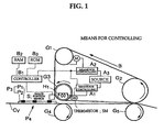
- FIG. 1 one example of an image fixing apparatus of the present invention furnished with heating and cooling function is shown.
- a resistance or a heat generation inducing body (H1) a guide roller (G3) which accommodates the heat generation inducing body within itself and which also acts as a heat fixing roller, an endless belt (B) entrained around the guide rollers (G1), (G2) and (G3), means for supplying pulse electricity to the heat generation inducing body (H1), and a pressure body (P4) which interposes a subject to be fixed (P3) bearing an image (P1) on a substrate (P2) between the pressure body (P4) and the endless belt (B), is provided.
- the pressure body (P4) in this example is configured by a conveyor belt (Cv) crossed from the pressure roller (G4) and the guide roller (G5).
- the guide roller (G1) and the guide roller (G2) may either be a drive roller and the other a driven roller, or either one of the rollers may be a cooling roller.
- the guide roller (G2) acts as the cooling roller for the image (P1) on the subject to be fixed (P3) which is conveyed in the direction of advance from left to right on the endless belt (B) as indicated by an arrow in the figure.
- the guide roller (G2) is configured to have a greater diameter than the guide roller (G3) which also acts as the fixing roller, or the guide roller (G1) which also acts as the driving roller, in order to secure enough surface area to be cooled.
- any means for cooling in addition to the guide roller (G2), or replacing the guide roller (G2) may be provided in the image fixing apparatus.
- the image (P1) on the subject to be fixed (P3) is heated with the heating body (H1) by way of endless belt (B), thereafter going through a process for cooling by the guide roller (G2) which also acts as means for cooling, and then the subject to be fixed bearing the image (P2) is separated from the endless belt (B).
- the controlling system of the image fixing apparatus in this example includes: means for controlling supply of electricity (A1) for a heater which is the heating body (H1) including means for switching supply of electricity, and means for controlling the rotation (A2) of a pulse motor (M) for driving the guide roller (G1) which also acts as drive roller, and these means for controlling (A1) and (A2) receives an image signal from the image position sensor (S) which monitors a location of the image (P1) on the subject to be fixed (P3).
- These means for controlling (A1) and (A2) are controlled by the controller (B1) connected to the RAM (B2) and ROM (B3), and controls supply of electricity from the electricity source (A3).
- the guide roller (G3) which also acts as heat fixing roller, is furnished with a thermal sensor such as thermistor (SM), and an output signal from the thermistor is sent to the means for controlling (A1) and used for switching operation to switch supply of electricity in the means for switching electricity (not shown in the drawings).
- the supply of electricity does not necessarily be a pulse electricity, and when the subject for controlling which is, for instance, a voltage and/or a electric current, is provided in an amount defined in analogue, it is not impossible to control the analogue amount using a digital signal as the subject to be controlled.
- supply of electricity is used as an amount of pulse electricity which is not only the amount for controlling, but also an amount to be controlled (subject for controlling). Needless to say the merit of such controlling system is well known by the ones skilled in the art.
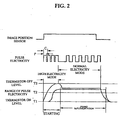
- FIG. 2 shows one example of a temperature variance for the electric pulse supplied to the heater (H1) in the means for controlling supply of electricity (A1), and the heater (H1).
- the heater (H1) when the image (P1) on the subject to be fixed (P3) reaches the heater (H1), the heater is well heated in the temperature as shown in the dotted-line, to melt fix the toner image. Thereafter, the means for electric supply only requires feeding a constant electric pulse having constant pulse width to the heater until the position sensor (S) no longer monitors the image on the substrate (P2) and the output signal becomes low in which the cutoff timing of the electric supply is synchronized, thereby the means for supplying electricity (A1) stops providing electricity to the heater (H1). However, the temperature of the heater (H1) still remains high enough to fix the remainder of the image after the electric supply is being cutoff.
- FIG. 3 is a block diagram showing one example of the control system in which the controller (B1) controls the means for controlling supply of electricity (A1) which provides pulse electricity to the heater (H1).
- the control system integrates a sensor (S) connected to the controller (B1), ROM (Read Only Memory - B3), RAM (Random Access Memory - B2), and a sequence program readable and updatable for sequentially controlling the means for controlling (A1) and (A2), and a program for interfacing a level signal of the thermal sensor (SM) acting as output of the inverter circuit (A12) and a pulse signal of the queue driver portion (A11) in a readable, updatable manner.
- SM level signal of the thermal sensor
- the respective data for Nn, Cn, and Pn are initially stored in the ROM (Read Only Memory) (B3) in advance in a manner to allow reading out.
- the retrieved data (Nn, Cn, and Pn) are sequentially sent to a register (B4) and to a data latch unit (B5), both of which are controlled by the controller (B1).
- the data Nn is sent to N pulse counter (B6), while data (Cn and Pn) are sent to the counter for determining length of time in supplying electricity (B7).
- the counter for determining length of time in supplying electricity determines a length in time for electric supply per one pulse data (Cj, Pk), and feeds the data to the queue driver (A11) of the means for controlling supply of electricity (A1).
- the queue driver (A11) outputs prescribed pulses in accordance with the sequential order of the data representing time of electric supply, and drives the heater (H1).
- the N Pulse counter (B6) counts the number of output electric pulses, and sends signal to the controller (B1) after counting reaches the data Ni.
- the controller (B1) outputs address signals for the next cycle, and also controls the register (B4) and the data latch unit (B5).
- the length of time for electric supply, number of pulses for each mode is defined based on the data collected in advance.
- such means for controlling supply of electricity (A1) may be varied in the fixing process for each of the image (P1) on a single subject to be fixed (P3).
- the means for controlling supply of electricity (A1) of the heater (H1) is shown as a mode having extended supply of electricity per pulse (P) in which the number of pulse electricity cycle is dense (C), and a normal (constant) mode which comes thereafter.
- the heater (H1) has an excellent heat-blocking property
- the temperature of the heater as the heating body may gradually increase, pulse width per unit time or the number of pulses provided to the heater (H1) preferably is reduced during the process for fixing from the start of heating until the end of heating for all of the images in a single subject to be fixed (P3).
- the means for controlling supply of electricity (A1) of the present invention to hold off supply of electricity to the heating body (H1) before the front edge of the image (P1) reaches the position of the heating body which is a heater (H1), and/or the means for supplying electricity (A1) to stop the supply of electricity immediately after the rear-edge of the image (P1) passes through the position of the heating body even if the rear-end of the substrate (2) bearing the image (P1) is still on its way to pass the position of the heating body.
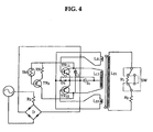
- FIG. 4 shows one example of a control circuit as a method for starting, ending, and switching supply of electricity to the heater (H1) controlled by the method for finely adjusting supply of electricity of the device of the present invention.
- a self-running multivibrator for the heating body (H1) is formed by a transistor (TR11) and a transistor (TR12).
- TR11 transistor
- TR12 transistor
- By electrically conducting the transistor (TR11) and the transistor (TR12) alternatively, secondary induction high voltage corresponding to alternating inputs to a primary coil (L11) of a transformer are output to the secondary coil (L21).
- the self-active multivibrator is controlled by a feed back circuit comprising a transistor (TR1), resist (Rx), and a thermistor (SM) as the thermal sensor in FIG. 1, in which a negative in-out relationship is established to a load fluctuation of the self-active multivibrator circuit.
- the self-active multivibrator is devised to conduct the primary coil (L11) of the transformer when one transistor (TR11) turns to be conductive. Consequently, while the secondary inductive output voltage is outputted to the secondary coil (L21) after a short while and then used as a heater source, the third inductive output voltage generated after a short while is output to the primary coil (L11) due to this secondary output voltage. Then, this third inductive output voltage generated after a short while is fed back to the other transistor (TR12) to render it conductive, and the transistor (TR12) functions in the same way as the transistor (TR11). Then, this operation is repeated alternatively to operate the multi-vibrator.
- a condenser (C1) is used to set a time constant (that is, a frequency of the pulse electricity) at the time of electrically conducting both transistors by cooperating with the primary coil (L11) of the circuit. Further, a direct current component from a rectifier (D) is given as the power supply to this circuit.
- this self-active multivibrator is used to determine the lowest and the highest limits in the temperatures during heating by the heater (H1) of the fixing device of the present invention. Hence, it determines the range of temperatures as illustrated in FIG. 2 by the means for controlling (A1).
- a push-pull type switch (SW) is configured to allow the heater (H1) to switch between a high calorific value (R1+R2) and a low calorific value (R2 only).
- a Zener diode which turns electrically conductive at the time of reaching zener break voltage is connected parallel to the resist (R3) plus rectifier (D) to protect the rectifier (D) from a sudden over voltage current, thus it is possible to provide an over current bypass path at the portion of a resist (R3) for the rectifier (D).
- a back electromotive force absorption circuit having a general high time constant, which includes the diode and the resistance.
- FIG. 6 there is shown another example of the control circuit as starting, ending, and switching methods for supplying electricity to the heating body (H1) in relation to the fixing device of the present invention.
- Another example of the control circuit for starting, stopping, and switching electricity supply to the heater (H1) of the fixing device of the present invention is shown in FIG. 6.
- the load resist (R1) of the heating body (H1) is expressed only by the resist (R1) of the heating body (H1) in a case of low temperature heating, and by the resist (R11+R12) for heating in high temperature, while means for switching temperature (7) is shown as an electric switch (SW).
- means for switching and opening-closing the line electricity supply to the heater (H1) is configured by an electric supply circuit control (CR) and the transistor (TR), the electric supply circuit control (CR) comprises an electromagnetic switch (X) for opening and closing the electromagnetic switch.
- the transistor (TR) amplifies output by a temperature sensor such as the thermistor (SM) for driving the electromagnetic switch (X).
- a temperature sensor such as the thermistor (SM) for driving the electromagnetic switch (X).
- SM thermistor
- the output signal is fed to the base electrode of the transistor (TR) through the thermistor (SM)
- this transistor (TR) turns electrically conductive, and magnetizes the electromagnetic switch (X).
- the circuit formed of the rectifier (D) and the resist (Rx2) in the example absorbs back electromotive force generated at the time of turning off the electromagnetic switch (X) in order to protect the circuit.
- the rectifier (D) is a power source for a method of controlling volume of electricity supply, comprised of the electric supply circuit
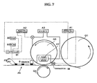
- FIG. 7 another example of the fixing device of the present invention is shown.
- the endless belt (B) is entrained about and links the guide rollers (G1), (G2) and the fixing roller (G3), however, it may also be arranged to nip the conveying belt (Cv) by the pressure roller (G4) and the guide roller (G3) positioned in the heater (H1), thereby conveying the subject for fixing by the force of friction.
- the guide roller (G1) also acting as the means for controlling is configured to have larger diameter than the pressure roller (G4) to ensure enough surface area for cooling.
- amount of electric supply as the subject to be controlled acquires a shape of pulse waveform.
- the amount of heat is diffused multi-dimensionally, and as shown in chart representing output amount of the heat from the roller (G3) in FIG. 8A to FIG. 8C, shaped in a single integral waveform in which the pulse output is integrated.
- FIG. 9A through FIG. 9D shows relationships of heat distributions of the integral waveforms of the electric pulse against the guide roller (G3).
- the items expressed as FIG. 9B and FIG. 9D are values of integrated pulses when the paper is conveyed past over the linear heating body, while FIG. 9A and FIG. 9C show the status of temperature variance of the fixing roller.
- the values of pulse-width, and pulse density (density of pulse electricity cycle) of FIG. 9A and FIG. 9B are left constant, and the temperature of the fixing roller with time is increased. On the contrary, the values of pulse integration with time are decreased for items FIG. 9C and FIG.
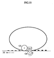
- FIG. 10 illustrates an influence of the guide roller (G1) to the heat distribution of the integrated waveforms shown in FIG. 9A through FIG. 9D, presented for each images, when the heating body (heater) of the present invention is configured in a shape of a rod. The saving of energy attained by the present invention is shown by actually feeding papers in the device.
- numerals 1 ⁇ through 5 ⁇ represent images on a sheet of paper, and each one of the images is heated with the integral waveforms controlled by the method of the present invention. Further, by using a toner having relatively low melt viscosity of 10 4 to print out three lines of solid images disposed 2 centimeters apart having 2 centimeters in width in the direction of advance, problems such as image expansion or off-setting was not caused due to an effect of controlled integral waveforms of the present invention, and for all three lines, a uniform solid images in quality were obtained.
- the present invention brings an explicit effect of stability in actual operation without causing off-settings and the like, and attains further energy savings using a process for fixing toner images and an image fixing apparatus of the present invention.
Landscapes
- Physics & Mathematics (AREA)
- General Physics & Mathematics (AREA)
- Fixing For Electrophotography (AREA)
- Developing Agents For Electrophotography (AREA)
- Control Of Resistance Heating (AREA)
Claims (18)
- Appareil de fixage d'images comprenant :ladite image (P1) étant formée par un toner comprenant un liant contenant comme constituant principal une résine, le point de ramollissement ou le point de fusion du toner se situant dans la gamme de 50 à 160°C, et la viscosité du toner se situant dans la gamme de 10 à 103 mPas à une température égale ou supérieure au point de ramollissement ou au point de fusion du toner,un corps de chauffage linéaire (H1);une courroie sans fin (B) entraínée autour de ce corps;un corps de pression (P4) pour intercaler un sujet devant être fixé (P3) possédant une image (P1) entre le corps de pression et la courroie sans fin (B);l'image (P1) sur le sujet (P3) devant être fixé étant chauffée par le corps de chauffage linéaire (H1) au moyen de la courroie sans fin (B) et étant ensuite refroidie et retirée de la courroie sans fin (B);
caractérisé par
des moyens pour appliquer une électricité sous forme impulsionnelle au corps de chauffage linéaire (H1); et
des moyens (A1) pour commander l'alimentation en électricité, qui commandent d'une manière variable la durée des impulsions et/ou la fréquence des impulsions de l'énergie envoyée au corps de chauffage linéaire (H1) pendant le processus de fixage de l'image (P1) sur un seul sujet (P3) devant être fixé pour l'application d'une quantité de chaleur variable au corps de chauffage linéaire (H1), ce qui permet d'empêcher un accroissement excessif de la température de surface du corps de chauffage linéaire (H1) pendant le passage du sujet (P3). - Dispositif de fixage d'images selon la revendication 1, caractérisé en ce que les moyens de délivrance d'une électricité sous forme d'impulsions comprennent des moyens (A1) pour commander l'envoi d'électricité, qui commandent d'une manière variable la durée des impulsions de l'électricité envoyée au corps de chauffage linéaire (H1) pendant le processus de fixage de l'image (P1) sur un seul sujet (P3) devant être fixé.
- Dispositif de fixage d'images selon la revendication 1, caractérisé en ce que les moyens pour délivrer une électricité sous la forme d'impulsions comprennent des moyens (A1) pour commander l'envoi d'électricité, qui commandent d'une manière variable la fréquence des impulsions de l'électricité envoyée au corps de chauffage linéaire (H1) pendant le processus de fixage de l'image (P1) sur un seul sujet (P3) devant être fixé.
- Dispositif de fixage d'images selon la revendication 1, caractérisé en ce que les moyens pour délivrer une électricité sous la forme d'impulsions comprennent des moyens (A1) pour commander l'envoi d'électricité, qui commandent d'une manière variable la durée des impulsions et la fréquence des impulsions de l'électricité envoyée au corps de chauffage linéaire (H1) pendant le processus de fixage de l'image (P1) sur un seul sujet (P3) devant être fixé.
- Dispositif de fixage d'images selon l'une quelconque des revendications 1 à 4, caractérisé en ce que les moyens (A1) pour commander l'envoi d'électricité réduisent la durée des impulsions ou la fréquence des impulsions de l'électricité sous forme impulsionnelle envoyée au corps de chauffage linéaire (H1) pendant le processus de fixage de l'image (P1) sur un seul sujet (P3) devant être fixé.
- Dispositif de fixage d'images selon l'une quelconque des revendications 1 à 5, caractérisé en ce que le rapport de l'envoi d'électricité du corps de chauffage (H1) au moment du démarrage du processus de fixage et au moment de la fin du processus de fixage pour le fixage d'un seul sujet devant être fixé et va de 10:9,5 à 10:1 lorsque le sujet (P3) devant être fixé est déplacé sur une longueur de 420 mm dans le sens machine (MD).
- Dispositif de fixage d'images selon l'une quelconque des revendications 1 à 6, caractérisé en ce que les moyens (A1) pour commander l'envoi d'électricité appliquent une ou plusieurs impulsions au corps de chauffage linéaire (H1) avant le fixage de la partie extrémité avant de l'image (P1) sur le sujet (P3), et atteint la position du corps de chauffage linéaire (H1).
- Dispositif de fixage d'images selon l'une quelconque revendications 1 à 7, caractérisé en ce que les moyens (A1) pour la commande d'envoi d'électricité débranchent l'alimentation en électricité appliquée au corps de chauffage linéaire (H1) avant que la partie d'extrémité avant de l'image (P1) sur le sujet (P3) devant être fixé n'atteigne la position du corps de chauffage linéaire (H1), conformément à un accumulateur de chaleur du corps de chauffage linéaire (H1) pour une seconde image et des images successives lorsque le sujet (P3) devant être fixé présente une pluralité d'images.
- Dispositif de fixage d'images selon l'une quelconque revendications 1 à 8, caractérisé en ce que les moyens (A1) pour commander l'envoi d'électricité s'arrêtent de délivrer de l'électricité une fois que la partie d'extrémité arrière de l'image (P1) franchit la position du corps de chauffage linéaire (H1) et avant que la partie d'extrémité arrière du sujet (P3) devant être fixé n'atteigne la position du corps de chauffage linéaire (H1).
- Dispositif de fixage d'images selon l'une quelconque revendications 1 à 9, caractérisé en ce que le corps de chauffage linéaire (H1) est prévu à l'intérieur d'un rouleau de guidage (G3) pourvu d'un capteur thermique (SM).
- Procédé pour fixer une image formée par un toner comprenant un liant contenant une résine en tant que constituant principal, le point de ramollissement ou le point de fusion du toner se situant dans la gamme de 50 à 160°C et la viscosité du toner se situant dans la gamme de 10 à 1013 mPas à une température égale ou supérieure au point de ramollissement ou au point de fusion du toner, ledit procédé comprenant :caractérisé en ce que ledit corps de chauffage linéaire reçoit de l'électricité sous la forme d'impulsions à partir de moyens servant à délivrer l'électricité sous forme d'impulsions, lesdits moyens pour délivrer l'électricité sous forme d'impulsions comprenant des moyens pour commander l'envoi d'électricité, qui commandent d'une manière variable la durée des impulsions et/ou la fréquence des impulsions de l'électricité envoyée au corps de chauffage linéaire pendant le processus de fixage de l'image sur une seul sujet devant être fixé.une étape pour chauffer une image sur un sujet devant être fixé au moyen d'un corps de chauffage linéaire à l'aide d'une courroie sans fin, le sujet devant être fixé étant intercalé entre un corps de pression et la courroie sans fin entraínée autour du corps de chauffage linéaire; etune étape de séparation du sujet devant être fixé par rapport à la courroie sans fin après que l'image a été refroidie;
- Procédé de fixage d'une image selon la revendication 11, caractérisé en ce qu'une combinaison de la durée d'impulsions et de la fréquence d'impulsions de l'électricité envoyée au corps de chauffage linéaire est commandée d'une manière variable pendant le traitement pour la fixation de l'image sur un seul sujet devant être fixé.
- Procédé de fixage d'une image selon l'une quelconque des revendications 11 ou 12, caractérisé en ce qu'une combinaison de la durée des impulsions et de la fréquence des impulsions de l'électricité envoyée au corps de chauffage linéaire est commandée d'une manière variable pendant le processus de fixage de l'image sur un seul sujet devant être fixé.
- Procédé de fixage d'une image selon l'une quelconque des revendications 11 à 13, caractérisé en ce que le rapport de l'envoi d'électricité du corps de chauffage au moment du démarrage du processus de fixage et au moment de la fin du processus de fixage pour le fixage d'un seul sujet devant être fixé et va de 10:9,5 à 10:1 lorsque le sujet devant être fixé est déplacé sur une longueur de 420 mm dans le sens machine (MD).
- Procédé de fixage d'une image selon l'une quelconque des revendications 11 à 14, caractérisé en ce qu'une ou plusieurs impulsions envoyées au corps de chauffage linéaire est (sont) appliquée(s) avant que la partie d'extrémité avant de l'image sur le sujet devant être fixé n'atteigne la position du corps de chauffage linéaire.
- Procédé de fixage d'une image selon l'une quelconque des revendications 11 à 15, caractérisé en ce que l'alimentation en électricité envoyée au corps de chauffage linéaire est maintenue débranchée avant que la partie d'extrémité avant de l'image sur le sujet devant être fixé n'atteigne la position du corps de chauffage linéaire, conformément à une accumulation de chaleur du corps de chauffage linéaire, pour une seconde image et des images successives lorsque le sujet devant être fixé possède une pluralité d'images.
- Procédé de fixage d'une image selon l'une quelconque des revendications 11 à 16, caractérisé en ce que l'envoi d'électricité au corps de chauffage linéaire est arrêté après que la partie d'extrémité arrière de l'image a franchi la position du corps de chauffage linéaire et avant que la partie d'extrémité arrière du sujet devant être fixé n'atteigne la position du corps de chauffage linéaire.
- Procédé de fixage d'une image selon l'une quelconque des revendications 11 à 17, caractérisé en ce que le corps de chauffage linéaire est prévu à l'intérieur d'un rouleau de guidage et l'alimentation en électricité est commandée par la température du rouleau de guidage.
Applications Claiming Priority (2)
| Application Number | Priority Date | Filing Date | Title |
|---|---|---|---|
| JP2001290062A JP3781650B2 (ja) | 2001-09-21 | 2001-09-21 | 画像定着方法及び画像定着装置 |
| JP2001290062 | 2001-09-21 |
Publications (3)
| Publication Number | Publication Date |
|---|---|
| EP1296200A2 EP1296200A2 (fr) | 2003-03-26 |
| EP1296200A3 EP1296200A3 (fr) | 2003-06-04 |
| EP1296200B1 true EP1296200B1 (fr) | 2005-08-10 |
Family
ID=19112456
Family Applications (1)
| Application Number | Title | Priority Date | Filing Date |
|---|---|---|---|
| EP02021032A Expired - Lifetime EP1296200B1 (fr) | 2001-09-21 | 2002-09-20 | Appareil de fixage d'images et procédé de fixation d'images |
Country Status (4)
| Country | Link |
|---|---|
| US (2) | US7046949B2 (fr) |
| EP (1) | EP1296200B1 (fr) |
| JP (1) | JP3781650B2 (fr) |
| DE (1) | DE60205438T2 (fr) |
Families Citing this family (17)
| Publication number | Priority date | Publication date | Assignee | Title |
|---|---|---|---|---|
| JP3781650B2 (ja) * | 2001-09-21 | 2006-05-31 | 株式会社リコー | 画像定着方法及び画像定着装置 |
| US7254360B2 (en) * | 2004-04-15 | 2007-08-07 | Ricoh Company, Ltd. | Image fixing apparatus, and, image forming apparatus having the same, and image forming process |
| JP3677767B1 (ja) | 2004-06-07 | 2005-08-03 | 株式会社アドバンテスト | ヒータ電力制御回路およびこれを用いたバーイン装置 |
| JP4845367B2 (ja) * | 2004-10-22 | 2011-12-28 | キヤノン株式会社 | 画像形成装置 |
| JP2007121653A (ja) * | 2005-01-26 | 2007-05-17 | Ricoh Co Ltd | 定着方法、定着装置、画像形成方法、画像形成装置 |
| JP4356666B2 (ja) * | 2005-08-29 | 2009-11-04 | 富士ゼロックス株式会社 | 加熱装置および定着装置 |
| JP2008058157A (ja) * | 2006-08-31 | 2008-03-13 | Brother Ind Ltd | 光量測定装置、画像形成装置およびトナー濃度測定装置 |
| US7885557B2 (en) * | 2008-12-16 | 2011-02-08 | Lexmark International, Inc. | Thermistor isolation technique for a ceramic fuser heater |
| JP2010217464A (ja) * | 2009-03-17 | 2010-09-30 | Ricoh Co Ltd | 画像形成装置 |
| JP5369907B2 (ja) * | 2009-06-03 | 2013-12-18 | 株式会社リコー | ベルト定着装置およびこれを有する画像形成装置 |
| US8457540B2 (en) * | 2009-09-15 | 2013-06-04 | Ricoh Company, Ltd. | Fixing device and image forming apparatus incorporating same |
| JP2012118481A (ja) * | 2010-11-10 | 2012-06-21 | Ricoh Co Ltd | 定着装置、画像形成装置、及び定着装置の制御方法 |
| JP5822061B2 (ja) | 2011-06-21 | 2015-11-24 | 株式会社リコー | 光沢付与装置、画像形成装置、カラー画像形成装置 |
| JP2013003517A (ja) | 2011-06-21 | 2013-01-07 | Ricoh Co Ltd | 光沢付与装置、定着装置、及び画像形成装置 |
| JP2013007801A (ja) | 2011-06-22 | 2013-01-10 | Ricoh Co Ltd | 光沢付与装置、及び画像形成装置 |
| JP5831740B2 (ja) | 2011-06-30 | 2015-12-09 | 株式会社リコー | 定着装置、および画像形成装置 |
| US9507299B1 (en) * | 2015-09-17 | 2016-11-29 | Kabushiki Kaisha Toshiba | Fixing device and image forming apparatus |
Family Cites Families (41)
| Publication number | Priority date | Publication date | Assignee | Title |
|---|---|---|---|---|
| JPS5513630B2 (fr) | 1974-08-28 | 1980-04-10 | ||
| JPH01263685A (ja) * | 1988-04-15 | 1989-10-20 | Canon Inc | 画像形成装置 |
| JP2516886B2 (ja) | 1987-06-16 | 1996-07-24 | キヤノン株式会社 | 像加熱装置 |
| JPH0769653B2 (ja) | 1988-10-14 | 1995-07-31 | キヤノン株式会社 | 定着装置 |
| DE68917688T2 (de) * | 1988-11-25 | 1995-01-05 | Canon Kk | Bildfixiergerät. |
| JP2632404B2 (ja) * | 1989-01-20 | 1997-07-23 | キヤノン株式会社 | 定着方法 |
| EP0397182B1 (fr) * | 1989-05-11 | 1995-01-18 | Canon Kabushiki Kaisha | Méthode de fixage par chaleur |
| JPH0334284A (ja) * | 1989-06-30 | 1991-02-14 | Kyocera Corp | 被加熱体の温度制御装置 |
| JPH04216580A (ja) * | 1990-12-17 | 1992-08-06 | Sharp Corp | ベルト定着装置 |
| JPH0519646A (ja) | 1991-02-28 | 1993-01-29 | Konica Corp | 定着装置 |
| US5245391A (en) | 1991-04-01 | 1993-09-14 | Ricoh Company, Ltd. | Developing device having surface microfields for an image forming apparatus |
| US5220383A (en) | 1991-04-01 | 1993-06-15 | Ricoh Company, Ltd. | Developing device for an image forming apparatus having a large number of microfields formed on a developer carrier |
| JPH052349A (ja) | 1991-06-25 | 1993-01-08 | Canon Inc | 定着装置 |
| US5869213A (en) | 1991-06-25 | 1999-02-09 | Ricoh Company, Ltd. | Multicolor image forming method preventing contamination of toner on an image carrier with toner on a developing carrier |
| US5444521A (en) * | 1991-07-15 | 1995-08-22 | Canon Kabushiki Kaisha | Image fixing device capable of controlling heating overshoot |
| JP3243696B2 (ja) | 1991-11-14 | 2002-01-07 | 株式会社リコー | 現像装置 |
| US5424814A (en) | 1992-01-11 | 1995-06-13 | Ricoh Company, Ltd. | Developing device with microfields formed on developer carrier |
| KR970003014B1 (ko) | 1992-02-16 | 1997-03-13 | 가부시끼가이샤 리코 | 다수의 마이크로필드를 형성할 수 있는 현상제 담체가 갖춰진 현상장치 |
| JP3170857B2 (ja) * | 1992-03-27 | 2001-05-28 | キヤノン株式会社 | 加熱装置 |
| JP3055304B2 (ja) * | 1992-04-10 | 2000-06-26 | キヤノン株式会社 | 像加熱装置 |
| JPH06175518A (ja) | 1992-12-09 | 1994-06-24 | Ricoh Co Ltd | 画像形成装置 |
| US5557392A (en) | 1992-12-22 | 1996-09-17 | Ricoh Company, Ltd. | Multicolor image forming apparatus with pulse voltage and DC voltage applied to a developing unit |
| JPH06194979A (ja) | 1992-12-25 | 1994-07-15 | Canon Inc | 定着装置及び転写材 |
| DE4416181C2 (de) | 1993-05-06 | 2003-01-30 | Ricoh Kk | Mehrfarben-Bilderzeugungseinrichtung |
| JPH0713410A (ja) | 1993-06-19 | 1995-01-17 | Ricoh Co Ltd | 現像装置 |
| JPH07146581A (ja) | 1993-11-22 | 1995-06-06 | Ricoh Co Ltd | 接触現像用一成分系磁性トナー |
| JP3005168B2 (ja) | 1994-12-28 | 2000-01-31 | キヤノン株式会社 | 定着装置 |
| US5801360A (en) * | 1994-10-05 | 1998-09-01 | Canon Kabushiki Kaisha | Image fixing apparatus |
| JP2676718B2 (ja) * | 1995-10-27 | 1997-11-17 | キヤノン株式会社 | 定着装置 |
| US5809386A (en) | 1995-12-25 | 1998-09-15 | Ricoh Company, Ltd. | Developing device for an image forming apparatus |
| JPH1020662A (ja) | 1996-06-28 | 1998-01-23 | Ricoh Co Ltd | 現像装置 |
| JPH112985A (ja) | 1997-06-12 | 1999-01-06 | Canon Inc | 画像定着装置及び画像定着方法 |
| JPH1138827A (ja) * | 1997-07-16 | 1999-02-12 | Toshiba Corp | 定着装置 |
| JPH1184941A (ja) * | 1997-09-11 | 1999-03-30 | Canon Inc | 画像形成装置 |
| JP2001147608A (ja) | 1999-09-08 | 2001-05-29 | Ricoh Co Ltd | トナー像定着装置 |
| JP2001154516A (ja) | 1999-11-24 | 2001-06-08 | Ricoh Co Ltd | 画像形成装置 |
| US6623897B2 (en) * | 1999-12-13 | 2003-09-23 | Ricoh Company, Ltd. | Image forming method |
| DE60114900T2 (de) | 2000-02-03 | 2006-08-10 | Ricoh Co., Ltd. | Elektrophotographischer Toner und Entwickler |
| JP2001228701A (ja) | 2000-02-14 | 2001-08-24 | Ricoh Co Ltd | 現像方法 |
| US6492084B2 (en) * | 2000-05-01 | 2002-12-10 | Ricoh Company, Ltd. | Toner for use in electrophotography and image formation method using the toner |
| JP3781650B2 (ja) * | 2001-09-21 | 2006-05-31 | 株式会社リコー | 画像定着方法及び画像定着装置 |
-
2001
- 2001-09-21 JP JP2001290062A patent/JP3781650B2/ja not_active Expired - Fee Related
-
2002
- 2002-09-20 DE DE60205438T patent/DE60205438T2/de not_active Expired - Lifetime
- 2002-09-20 US US10/247,631 patent/US7046949B2/en not_active Expired - Fee Related
- 2002-09-20 EP EP02021032A patent/EP1296200B1/fr not_active Expired - Lifetime
-
2006
- 2006-03-21 US US11/384,496 patent/US7356298B2/en not_active Expired - Fee Related
Also Published As
| Publication number | Publication date |
|---|---|
| EP1296200A2 (fr) | 2003-03-26 |
| EP1296200A3 (fr) | 2003-06-04 |
| US20060159477A1 (en) | 2006-07-20 |
| DE60205438T2 (de) | 2006-06-01 |
| US7356298B2 (en) | 2008-04-08 |
| DE60205438D1 (de) | 2005-09-15 |
| JP3781650B2 (ja) | 2006-05-31 |
| US7046949B2 (en) | 2006-05-16 |
| JP2003098862A (ja) | 2003-04-04 |
| US20030059224A1 (en) | 2003-03-27 |
Similar Documents
| Publication | Publication Date | Title |
|---|---|---|
| US7046949B2 (en) | Image fixing apparatus using pulsating power for heating | |
| US6055390A (en) | Fixing device and method for controlling fixing temperature in a stable manner | |
| US8218993B2 (en) | Belt conveyance apparatus and image heating apparatus | |
| US20020031363A1 (en) | Method and apparatus for image forming capable of performing an effective fixing process | |
| EP0370520B1 (fr) | Appareil de fixation d'image | |
| EP1193573B1 (fr) | Dispositif de formation d'images | |
| JP2001154516A (ja) | 画像形成装置 | |
| US6011938A (en) | Fixing device in image forming device | |
| US12204264B2 (en) | Image forming apparatus with recording material conveyance control | |
| US6718155B2 (en) | Fixing apparatus in which fixing speed is switched during cleaning | |
| JPH0996991A (ja) | 加熱定着装置及び画像形成装置 | |
| US7792450B2 (en) | Fixing device for image forming apparatus and control method thereof | |
| JP2002116658A (ja) | 定着装置の制御方法 | |
| EP0990959B1 (fr) | Système d'impression électrophotographique recto-verso | |
| JP2003098863A (ja) | 定着装置 | |
| EP0917013B1 (fr) | Appareil de formation d'images avec separation des feuilles améliorée en controllant la quantité de toner du fond pour l'impression au rerso | |
| JP2003345164A (ja) | 定着装置および画像形成装置 | |
| JP2657990B2 (ja) | 画像形成装置 | |
| JP2006323413A (ja) | 定着装置 | |
| JPH0836323A (ja) | 画像形成装置 | |
| JP4343422B2 (ja) | 加熱装置及び画像形成装置 | |
| JPH0769653B2 (ja) | 定着装置 | |
| JP2001305905A (ja) | 画像形成装置 | |
| JP2004138839A (ja) | 像加熱装置 | |
| JPH0277775A (ja) | 画像形成装置 |
Legal Events
| Date | Code | Title | Description |
|---|---|---|---|
| PUAI | Public reference made under article 153(3) epc to a published international application that has entered the european phase |
Free format text: ORIGINAL CODE: 0009012 |
|
| AK | Designated contracting states |
Designated state(s): AT BE BG CH CY CZ DE DK EE ES FI FR GB GR IE IT LI LU MC NL PT SE SK TR Kind code of ref document: A2 Designated state(s): AT BE BG CH CY CZ DE DK EE ES FI FR GB GR IE IT LI LU MC NL PT SE SK TR |
|
| AX | Request for extension of the european patent |
Extension state: AL LT LV MK RO SI |
|
| PUAL | Search report despatched |
Free format text: ORIGINAL CODE: 0009013 |
|
| AK | Designated contracting states |
Designated state(s): AT BE BG CH CY CZ DE DK EE ES FI FR GB GR IE IT LI LU MC NL PT SE SK TR |
|
| AX | Request for extension of the european patent |
Extension state: AL LT LV MK RO SI |
|
| 17P | Request for examination filed |
Effective date: 20030714 |
|
| 17Q | First examination report despatched |
Effective date: 20031016 |
|
| AKX | Designation fees paid |
Designated state(s): DE FR GB |
|
| GRAP | Despatch of communication of intention to grant a patent |
Free format text: ORIGINAL CODE: EPIDOSNIGR1 |
|
| GRAS | Grant fee paid |
Free format text: ORIGINAL CODE: EPIDOSNIGR3 |
|
| GRAA | (expected) grant |
Free format text: ORIGINAL CODE: 0009210 |
|
| AK | Designated contracting states |
Kind code of ref document: B1 Designated state(s): DE FR GB |
|
| REG | Reference to a national code |
Ref country code: GB Ref legal event code: FG4D |
|
| REF | Corresponds to: |
Ref document number: 60205438 Country of ref document: DE Date of ref document: 20050915 Kind code of ref document: P |
|
| ET | Fr: translation filed | ||
| PLBE | No opposition filed within time limit |
Free format text: ORIGINAL CODE: 0009261 |
|
| STAA | Information on the status of an ep patent application or granted ep patent |
Free format text: STATUS: NO OPPOSITION FILED WITHIN TIME LIMIT |
|
| 26N | No opposition filed |
Effective date: 20060511 |
|
| REG | Reference to a national code |
Ref country code: DE Ref legal event code: R082 Ref document number: 60205438 Country of ref document: DE Representative=s name: MEISSNER, BOLTE & PARTNER GBR, DE Ref country code: DE Ref legal event code: R082 Ref document number: 60205438 Country of ref document: DE Representative=s name: MEISSNER BOLTE PATENTANWAELTE RECHTSANWAELTE P, DE |
|
| REG | Reference to a national code |
Ref country code: DE Ref legal event code: R082 Ref document number: 60205438 Country of ref document: DE Representative=s name: MEISSNER, BOLTE & PARTNER GBR, DE |
|
| REG | Reference to a national code |
Ref country code: FR Ref legal event code: PLFP Year of fee payment: 14 |
|
| PGFP | Annual fee paid to national office [announced via postgrant information from national office to epo] |
Ref country code: FR Payment date: 20150626 Year of fee payment: 14 |
|
| PGFP | Annual fee paid to national office [announced via postgrant information from national office to epo] |
Ref country code: GB Payment date: 20150917 Year of fee payment: 14 Ref country code: DE Payment date: 20150922 Year of fee payment: 14 |
|
| REG | Reference to a national code |
Ref country code: DE Ref legal event code: R119 Ref document number: 60205438 Country of ref document: DE |
|
| GBPC | Gb: european patent ceased through non-payment of renewal fee |
Effective date: 20160920 |
|
| REG | Reference to a national code |
Ref country code: FR Ref legal event code: ST Effective date: 20170531 |
|
| PG25 | Lapsed in a contracting state [announced via postgrant information from national office to epo] |
Ref country code: DE Free format text: LAPSE BECAUSE OF NON-PAYMENT OF DUE FEES Effective date: 20170401 Ref country code: FR Free format text: LAPSE BECAUSE OF NON-PAYMENT OF DUE FEES Effective date: 20160930 Ref country code: GB Free format text: LAPSE BECAUSE OF NON-PAYMENT OF DUE FEES Effective date: 20160920 |