EP1299883B1 - Einfache chipidentifizierung - Google Patents
Einfache chipidentifizierung Download PDFInfo
- Publication number
- EP1299883B1 EP1299883B1 EP01962828A EP01962828A EP1299883B1 EP 1299883 B1 EP1299883 B1 EP 1299883B1 EP 01962828 A EP01962828 A EP 01962828A EP 01962828 A EP01962828 A EP 01962828A EP 1299883 B1 EP1299883 B1 EP 1299883B1
- Authority
- EP
- European Patent Office
- Prior art keywords
- circuits
- portions
- electrical device
- circuit
- current
- Prior art date
- Legal status (The legal status is an assumption and is not a legal conclusion. Google has not performed a legal analysis and makes no representation as to the accuracy of the status listed.)
- Expired - Lifetime
Links
Images

Classifications
-
- G—PHYSICS
- G01—MEASURING; TESTING
- G01R—MEASURING ELECTRIC VARIABLES; MEASURING MAGNETIC VARIABLES
- G01R31/00—Arrangements for testing electric properties; Arrangements for locating electric faults; Arrangements for electrical testing characterised by what is being tested not provided for elsewhere
-
- H—ELECTRICITY
- H10—SEMICONDUCTOR DEVICES; ELECTRIC SOLID-STATE DEVICES NOT OTHERWISE PROVIDED FOR
- H10W—GENERIC PACKAGES, INTERCONNECTIONS, CONNECTORS OR OTHER CONSTRUCTIONAL DETAILS OF DEVICES COVERED BY CLASS H10
- H10W46/00—Marks applied to devices, e.g. for alignment or identification
-
- H—ELECTRICITY
- H10—SEMICONDUCTOR DEVICES; ELECTRIC SOLID-STATE DEVICES NOT OTHERWISE PROVIDED FOR
- H10W—GENERIC PACKAGES, INTERCONNECTIONS, CONNECTORS OR OTHER CONSTRUCTIONAL DETAILS OF DEVICES COVERED BY CLASS H10
- H10W46/00—Marks applied to devices, e.g. for alignment or identification
- H10W46/401—Marks applied to devices, e.g. for alignment or identification for identification or tracking
- H10W46/403—Marks applied to devices, e.g. for alignment or identification for identification or tracking for non-wireless electrical read out
Definitions
- the present invention relates generally to techniques for identifying circuits within electrical devices.
- Electrical devices commonly consist of one or more circuit boards mounted inside some manner of mechanical case. These circuit boards further commonly have a number of circuits mounted on each board. Often there is a need to identify one or more of the circuits mounted on each board within the electrical device. For example, in the instance where the device is to be loaded with new software and the proper version of software is dependent on the identities of the circuits within the electrical device, it would be necessary to determine the identities of the circuits within the electrical device. A manual inspection of the electrical device may, of course, be conducted. Such a manual inspection, however, will likely require some lengthy disassembly. Furthermore, even after disassembly, the identity of the individual circuits on the circuit boards may not be so readily apparent as to make them easily identifiable by visual inspection. Thus, it would be advantageous to have the capability to electrically communicate the identity of one or more circuits located within an electrical device to an external entity.
- JP03082560 A discloses a system for detecting a faulty IC in a plurality of serially connected driver ICs. Heating elements are successively driven one by one by the driver IC and a change in the consumed electric current is measured to successively check the output bits of the circuit.
- US3737769 discloses a current testing system for non-destructively detecting voids in dry type insulating structures such as the stator coil of generators or motors. This is achieved by obtaining current-voltage characteristic curves at which the current is suddenly changed and estimating the breakdown voltage.
- a method of identifying a circuit within an electrical device comprising a plurality of circuits or portions of circuits, the method comprising the steps of: measuring a first current drawn by the plurality of circuits or portions of circuits of the electrical device; for a number of times, n , successively controlling at least a first portion of the plurality of circuits or portions of circuits so as to affect the current drawn by one of said plurality of the circuits or portions of circuits, by successively supplying a first control signal to the electrical device, which first control signal is supplied to another of said plurality of circuits or portions of circuits within the electrical device; and for each of the first control signals supplied to said another of said plurality of circuits or portions of circuits generating a second control signal in said another of said plurality of circuits or portions of circuits and supplying the second control signal to the first portion of the plurality of circuits or portions of circuits so as to affect the current drawn by said one of said plurality of circuits
- a system for identifying a circuit within an electrical device comprising a plurality of circuits or portions of circuits
- the system comprising: logic that measures a first current drawn by said plurality of circuits or portions of circuits of the electrical device, logic that, for a number of times, n, successively controls at least a portion of said plurality of circuits or portions of circuits so as to affect the current drawn by one of said plurality of circuits or portions of circuits, and successively supplies a first control signal to the electrical device, which first control signal is supplied to another of said plurality of circuits or portions of circuits within the electrical device; and that, for each of the first control signals supplied to said another of said plurality of circuits or portions of circuits, generates a second control signal in said another of said plurality of said circuits or portions of circuits and supplies the second control signal to the portion of said plurality of circuits or portions of circuits so as to affect the current drawn by said one of said plurality of
- any such form of embodiment may be referred to herein as "logic configured to” perform a described action, or altematively as “logic that” performs a described action.
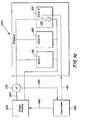
- Fig. 1 a illustrates an example of a circuit which does not form part of the present invention that can be used where the circuits that are to be identified within an electrical device are capable to receiving one-way communication.
- an electrical device 100 may contain a number of circuits, such as for example, a number of Application Specific Integrated Circuits (ASIC's). For purposes of illustration, however, only three ASIC's 115, 120, and 125 are shown in Fig. 1a.
- ASIC Application Specific Integrated Circuits
- additional monitoring and control devices are connected to the electrical device 100.
- a power supply 105 is connected, through an ammeter 110, to each ASIC (115, 120, and 125) to provide a supply of current to each.
- a controller 130 is additionally connected to the power supply 105, via control line 140, and to the ASIC3 125 that is to be identified, via one-way bus 145.
- Identification of ASIC3 125 is initiated by the controller 130 sending a command, via line 140, to the power supply 105.
- This command sets a specified voltage level that is to be supplied via the power supply line 160 to the ASIC's.
- the power supply voltage may be fixed and, thus, the controller will not be required to send a voltage level setting command to the power supply 105.
- an ammeter 110 is placed in series with power supply line 160 to monitor the sum of the currents drawn by the ASIC's at an initial time t 1 . The monitored current level at time t 1 is then reported to the controller 130 via communication line 155.
- the controller 130 stores in memory the sum of currents drawn by the ASIC's, denoted herein as the reference current i ref .
- the controller 130 then initiates a command over the one-way bus 145 to "switch in” a current path 150 that is associated with, or located within, the ASIC that is to be identified (identification of ASIC3 is shown in Fig. 1).
- "Switching in” current path 150 causes a different amount of current i ref + ⁇ i to flow from the power supply 105.
- the sum of the currents drawn by the ASICs at a second time t 2 is measured by the ammeter 110 and the measurement is reported to the controller 130.
- the controller 130 then subtracts the sum of the drawn current measured at t 2 from the sum of the drawn current i ref measured at time t 1 .
- the subtracted result is equal to the change in current ⁇ i attributable to current path 150.
- Current path 150 can be designed such that the different current drawn by the path 150 corresponds to identities of ASIC3 125.
- the current drawn by the path can be associated with different types of ASIC's, with the same type of ASIC but manufactured by different vendors, or with different versions of the same type of ASIC manufactured by the same vendor. Thus, each version of ASIC will draw a different ⁇ i and the ⁇ i determined by the controller as described above can be used to identify the ASIC.
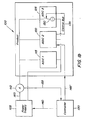
- Fig. 1 b illustrates an embodiment of the invention.
- the arrangement of Fig. 1 b is similar to that of Fig. 1a, except that here, the one-way bus 145' does not go to the ASIC to be measured (ASIC3 125), but instead connects the controller 130 to the second ASIC, ASIC2 120.
- ASIC2 120 has a control bus 135 that supplies a control signal for "switching in/out" the current path 150. This is done in response to a command received by ASIC2 120 via the one-way bus 145'.
- the operation of this arrangement is otherwise the same as that described above with respect to Fig. 1a, and will therefore not be repeated.
- one or more current sinking paths can be incorporated into, or associated with the circuit.
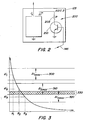
- One example of such current sinking circuitry is shown in Fig. 2.
- This current sinking path 200 comprises a resistor 205 in series with a switch transistor 210.
- transistor switch 210 When an "activation" command is received from controller 130 over the one-way bus 145, transistor switch 210 is "turned on”. An additional current, above and beyond the current nominally drawn by ASIC3 125, is then drawn through the resistor 205. The additional current ⁇ i is thus set by the value of the resistance of the resistor 205.
- a limit on the number of different versions or revisions of circuit ASIC3 125 that can be identified is set by the accuracy of the resistor 205.
- resistor accuracies ie. deviations from nominal values
- the accuracy of the resistor 205 (Fig. 2), selected for use in sink path 200 (Fig. 2), will determine the range of different currents ⁇ i over which a circuit's identification can be made.
- Different resistance values for resistor 205 eg. R 1 , R 2 , R 3 , «
- R n can only be used where their deviations from nominal values will not produce ranges of difference currents ( ⁇ i ) that "overlap”.
- the maximum tolerances of R 1 and R 2 produce ranges of difference currents corresponding to ⁇ i 1max 300 and ⁇ i 2max 310, respectively. Since, as shown in the figure, there is no "overlap" of these two ranges of difference currents, the circuit revisions/versions that corresponding to R 1 and R 2 can be easily distinguished. However, as shown at 330 in Fig. 3, if the value of R 3 is selected such that its inaccuracies produces a range of difference currents that may "overlap" the difference currents of R 2 , then an inaccurate identification of the ASIC associated with R 2 or R 3 may be made.
- One exemplary solution to the limitation on the number of circuit versions that can be identified uses two current sinking paths that contain resistors with matched resistance values.
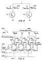
- One example of such a solution is illustrated in Fig. 4, where matched resistors R Match1 400 and R Match2 405 are used for identifying the associated circuit version.
- each of the resistors R Match1 400 and R Match2 405 may have resistance values that deviate as much as 20% or more from nominal values, these resistors are matched together such that their actual resistance values are within a very low tolerance value of one another (approximately 1%).
- the two current paths are "activated" successively or simultaneously and the ratios of the measured difference currents ⁇ i Match1 and ⁇ i Match2 can be determined to identify the circuit.
- the version of the ASIC circuitry would be set by the multiple of R Match1 chosen for R Match2 ⁇
- R Match2 is selected such that its actual resistance value is a fraction (1/n) of the resistance value of R Match1.
- the error in circuit identification is thus determined by the matching tolerance between R Match1 and R Match2 .
- ASIC3 can be configured such that less current is drawn from the power supply 105 in response to an instruction from controller 130.
- the control signal over one-way 145 may "switch in" additional resistance in ASIC3 so as to limit the current drawn from power supply 105.
- FIG. 5 Another example of an identification circuit is illustrated in Fig. 5.
- This provides circuit identification in the device configuration where the circuit to be identified (ASIC2 in the figure) does not have the capability of communicating by either a one-way or a two-way bus, but does have an output 260 that can be monitored by at least one other circuit 225 within the electrical device 200. Additionally, the circuit to be identified must be controllable by a control signal 265 such as, for example, a one-way bus or a single control signal (eg. one logic pin) within the electrical device 200.
- a control signal 265 such as, for example, a one-way bus or a single control signal (eg. one logic pin) within the electrical device 200.
- the ASIC2 200 generates analog signals rather than digital logic signals
- the monitoring circuit ASIC3 225 may contain an analog-to-digital (A/D) converter for converting the analog output voltage or current signal from ASIC2 220 into a digital signal.
- the monitoring circuit 225 may contain a logic interface for receiving one or more logic signals from ASIC2 220.
- ASIC2 220 and the A/D converter of ASIC3 225 are used for purposes other than circuit identification when the electrical device 200 is operating normally.
- the circuit identification function is a special mode of operation that can be initiated by the controller 230.
- ASIC2 220 produces an analog voltage or current signal in response to a control signal 265 from ASIC1 215, an A/D converter in ASIC3 225 converts the analog signal to a digital representation that can be used for identifying ASIC2 220.
- controller 230 instructs ASIC1 215 to initiate a command over the one-way bus/logic pin 265 to cause ASIC2 220 to output an analog voltage or current signal.
- the A/D converted analog voltage or current signal is then communicated over the two-way bus 245 to the controller 230.
- the controller 230 then identifies ASIC2 220 based on the digital representation received from ASIC3 225.
- ASIC1 215, ASIC2 220, ASIC3 225 can be different portions of the same circuit.
- ASIC1 215 could be a controller in the digital baseband circuitry of a transceiver of a radiocommunication device and ASIC3 225 could be the mixed signal baseband circuit, containing an A/D converter, in the transceiver of the radiocommunication device.
- the circuitry represented by ASIC2 220 could be the intervening circuitry between the controller and the mixed-signal baseband circuit, or alternatively could be any circuit in the product.
- the output from ASIC2 220 would be one or more logic signals.
- the one or more logic signals received by ASIC3 225 would then be communicated over two-way bus 245 to controller 230 for identification of ASIC2 220.
- ASIC1 215 first initiates a logic command in response to an instruction from controller 230 which requests ASIC2 220 to identify itself. To perform this function, ASIC2 220 could use a parallel input shift register such as the 4 bit register 600 shown in Fig. 6.
- the parallel inputs (P1, P2, P3, P4) 605 to the shift register in this case are selected so as to uniquely specify the identity of ASIC2 220 and could be, for example, hard wired through the direct connection of the parallel inputs either to a ground connection (for a logic low) or to the power supply voltage (for a logic high).
- the logic control signal from ASiC1 215 would initiate the loading of the hard coded identity inputs to the shift register in the following fashion.
- all RS flip-flops 610 would first be cleared (clear input is high) and the NAND gates 615 with output A, B,C and D 620 feeding the preset terminals (Pr) 620 would initially be disabled by applying a low parallel-enable (PE) voltage.
- the clear input 625 would be set to low and the PE terminal 630 would be set to high so as to apply the hard coded identity word to the respective Pr inputs 620 of the RS flip-flops 610.
- the hard wired data word would thus be transferred to the internal preset terminals A, B, C and D 620, and to the flip-flop outputs, independent of the clock.
- the PE level 630 is then set low to disable the NAND gates 615, and application of three clock pulses at the Clock input 635 would cause the hard coded identity word to appear serially at the output terminal Q3 640.
- Changes in circuit identity can be made by changing the hard coded inputs to the shift register.
- the shift register illustrated in Fig. 6 could be modified to include more flip-flops, thus increasing the resolution of the ASIC identity word.
- the number of possible circuits that can be identified by means of the above-described circuit is achieved by performing additional measurements (either in parallel or in series) to generate a plurality of current measurements. That is, for a number of times, n , at least a portion of the circuit is successively controlled so as to affect the current drawn by the circuit, and for each of the n times, the affected current drawn by the circuit is measured.
- n is a number greater than 1.
- the identity of the circuit is determined using n values corresponding to the difference between each of the n affected currents and the first current.
Landscapes
- Physics & Mathematics (AREA)
- General Physics & Mathematics (AREA)
- Tests Of Electronic Circuits (AREA)
- Semiconductor Integrated Circuits (AREA)
- Crystals, And After-Treatments Of Crystals (AREA)
- Peptides Or Proteins (AREA)
- Polysaccharides And Polysaccharide Derivatives (AREA)
Claims (4)
- Verfahren zum Identifizieren einer Schaltung (125) innerhalb einer elektrischen Einrichtung (100), wobei die elektrischen Einrichtung (100) eine Vielzahl von Schaltungen oder Schaltungsteilen (115, 120, 125) umfasst, und wobei das Verfahren die Schritte umfasst:Messen eines ersten Stroms (iref), der von der Vielzahl von Schaltungen oder Schaltungsteilen (115, 120, 125) der elektrischen Einrichtung (100) gezogen wird;für eine Anzahl n von Vorgängen (t1, t2), sukzessives Steuern mindestens eines ersten Teils der Vielzahl von Schaltungen oder Schaltungsteilen (115, 120, 125), um den durch eine bzw. einen der Vielzahl von Schaltungen oder Schaltungsteilen (115, 120, 125) gezogenen Strom durch sukzessives Zuführen eines ersten Steuersignals zu der elektrischen Einrichtung (100) zu beeinflussen, welches erste Steuersignal einer bzw. einem anderen der Vielzahl von Schaltungen oder Schaltungsteilen (115, 120, 125) innerhalb der elektrischen Einrichtung (100) zugeführt wird; und für jedes der bzw. dem anderen der Vielzahl von Schaltungen oder Schaltungsteilen (115, 120, 125) zugeführte erste Steuersignal, Erzeugen eines zweiten Steuersignals in der bzw. dem anderen der Vielzahl von Schaltungen oder Schaltungsteilen (115, 120, 125) und Zuführen des zweiten Steuersignals zu dem ersten Teil der Vielzahl von Schaltungen oder Schaltungsteilen (115, 120, 125), um den durch die eine bzw. den einen der Vielzahl von Schaltungen oder Schaltungsteilen (115, 120, 125) gezogenen Strom zu beeinflussen, und für jeden der n Vorgänge, Messen des von der bzw. dem einen der Vielzahl von Schaltungen oder Schaltungsteilen (115, 120, 125) gezogenen beeinflussten Stroms; undBestimmen der Identität der Schaltung (125) unter Verwendung von n Werten, die der Differenz (Δi) zwischen jeweiligen der n beeinflussten Ströme und dem ersten Strom (iref) entsprechen, dadurch gekennzeichnet, dass n eine Zahl größer als 1 ist und dass die n Messwerte, wenn gemeinsam betrachtet, ein Wort zum Identifizieren der Schaltung (125) bilden.
- Verfahren nach Anspruch 1, ferner umfassend:zuerst, Steuern eines Versorgungsspannungspegels der elektrischen Einrichtungen (100).
- System zum Identifizieren einer Schaltung (125) innerhalb einer elektrischen Einrichtung (100), wobei die elektrischen Einrichtung (100) eine Vielzahl von Schaltungen oder Schaltungsteilen (115, 120, 125) umfasst, wobei das System umfasst:eine Logik, die einen ersten Strom (iref) misst, der von der Vielzahl von Schaltungen oder Schaltungsteilen (115, 120, 125) der elektrischen Einrichtungen (100) gezogen wird,eine Logik, die für eine Anzahl n Vorgänge sukzessive mindestens einen Teil der Vielzahl von Schaltungen oder Schaltungsteilen (115, 120, 125) steuert, um den durch eine bzw. einen der Vielzahl von Schaltungen oder Schaltungsteilen (115, 120, 125) gezogenen Strom zu beeinflussen, und ein erstes Steuersignals zu der elektrischen Einrichtung (100) sukzessive zuführt, welches erste Steuersignal einer bzw. einem anderen der Vielzahl von Schaltungen oder Schaltungsteilen (115, 120, 125) innerhalb der elektrischen Einrichtungen (100) zugeführt wird; und die für jeweilige der der bzw. dem anderen der Vielzahl von Schaltungen oder Schaltungsteilen (115, 120, 125) zugeführten ersten Steuersignale ein zweites Steuersignal in der bzw. dem anderen der Vielzahl von Schaltungen oder Schaltungsteilen (115, 120, 125) erzeugen, und das zweite Steuersignal dem Teil der Vielzahl von Schaltungen oder Schaltungsteilen (115, 120, 125) zuführt, um den durch die eine bzw. den einen der Vielzahl von Schaltungen oder Schaltungsteilen (115, 120, 125) gezogenen Strom zu beeinflussen, und für jeden der n Vorgänge, den durch den einen bzw. die eine der Vielzahl von Schaltungen oder Schaltungsteilen (115, 120, 125) gezogenen beeinflussten Strom misst; undeine Logik, die die Identität der Schaltung (220) unter Verwendung von n Werten bestimmt, die der Differenz zwischen jeweiligen der n beeinflussten Ströme und dem ersten Strom entsprechen, dadurch gekennzeichnet, dass n eine Zahl ist, die größer ist als 1 und dass die n Messwerte, wenn gemeinsam betrachtet, ein Wort zum Identifizieren der Schaltung (125) bilden.
- System nach Anspruch 3, ferner umfassend:eine Logik, die zuerst einen Versorgungsspannungspegel der elektrischen Einrichtung (100) steuert.
Applications Claiming Priority (3)
| Application Number | Priority Date | Filing Date | Title |
|---|---|---|---|
| US614583 | 1984-05-29 | ||
| US09/614,583 US6483335B1 (en) | 2000-07-12 | 2000-07-12 | Simple chip identification |
| PCT/EP2001/007674 WO2002009114A2 (en) | 2000-07-12 | 2001-07-05 | Simple chip identification |
Publications (2)
| Publication Number | Publication Date |
|---|---|
| EP1299883A2 EP1299883A2 (de) | 2003-04-09 |
| EP1299883B1 true EP1299883B1 (de) | 2006-06-21 |
Family
ID=24461883
Family Applications (1)
| Application Number | Title | Priority Date | Filing Date |
|---|---|---|---|
| EP01962828A Expired - Lifetime EP1299883B1 (de) | 2000-07-12 | 2001-07-05 | Einfache chipidentifizierung |
Country Status (8)
| Country | Link |
|---|---|
| US (1) | US6483335B1 (de) |
| EP (1) | EP1299883B1 (de) |
| KR (1) | KR20030015887A (de) |
| AT (1) | ATE331287T1 (de) |
| AU (1) | AU2001283923A1 (de) |
| DE (1) | DE60120978T2 (de) |
| MY (1) | MY124516A (de) |
| WO (1) | WO2002009114A2 (de) |
Families Citing this family (3)
| Publication number | Priority date | Publication date | Assignee | Title |
|---|---|---|---|---|
| DE10319935A1 (de) * | 2003-05-02 | 2004-11-18 | Deutsche Thomson-Brandt Gmbh | Verfahren zur Bereitstellung einer Bedienoberfläche zur Bedienung eines Gerätes in einem Netzwerk verteilter Stationen sowie Netzwerkgerät für die Durchführung des Verfahrens |
| KR100700150B1 (ko) * | 2004-10-06 | 2007-03-29 | 주식회사 미래엔지니어링 | 오·폐수 중 질소제거장치 및 이를 이용한 질소제거방법 |
| US7960985B2 (en) * | 2008-01-25 | 2011-06-14 | Hewlett-Packard Development Company, L.P. | Identification of integrated circuit |
Family Cites Families (8)
| Publication number | Priority date | Publication date | Assignee | Title |
|---|---|---|---|---|
| JPS514791B1 (de) | 1971-03-16 | 1976-02-14 | ||
| EP0128986B1 (de) * | 1982-12-23 | 1991-02-27 | Sumitomo Electric Industries Limited | Monolithische integrierte Mikrowellenschaltung und Verfahren zum Auswählen derselben |
| JPH0382560A (ja) | 1989-08-25 | 1991-04-08 | Sharp Corp | サーマルヘッド検査方式 |
| JPH0555339A (ja) | 1991-08-23 | 1993-03-05 | Fujitsu Ltd | 半導体デバイス測定装置 |
| JPH08136612A (ja) | 1994-11-04 | 1996-05-31 | Hitachi Ltd | 電子装置の電気特性測定方法および測定装置 |
| US6202181B1 (en) * | 1996-11-04 | 2001-03-13 | The Regents Of The University Of California | Method for diagnosing bridging faults in integrated circuits |
| US6222358B1 (en) * | 1997-08-25 | 2001-04-24 | Ntc, Inc. | Automatic circuit locator |
| DE19852917A1 (de) | 1998-11-17 | 2000-05-25 | Bosch Gmbh Robert | Verfahren und Anordnung zur Ermittlung der Leerlaufspannung einer Batterie |
-
2000
- 2000-07-12 US US09/614,583 patent/US6483335B1/en not_active Expired - Lifetime
-
2001
- 2001-06-21 MY MYPI20012945 patent/MY124516A/en unknown
- 2001-07-05 AT AT01962828T patent/ATE331287T1/de not_active IP Right Cessation
- 2001-07-05 AU AU2001283923A patent/AU2001283923A1/en not_active Abandoned
- 2001-07-05 EP EP01962828A patent/EP1299883B1/de not_active Expired - Lifetime
- 2001-07-05 DE DE60120978T patent/DE60120978T2/de not_active Expired - Lifetime
- 2001-07-05 KR KR10-2003-7000530A patent/KR20030015887A/ko not_active Ceased
- 2001-07-05 WO PCT/EP2001/007674 patent/WO2002009114A2/en not_active Ceased
Also Published As
| Publication number | Publication date |
|---|---|
| WO2002009114A2 (en) | 2002-01-31 |
| AU2001283923A1 (en) | 2002-02-05 |
| DE60120978T2 (de) | 2006-11-09 |
| MY124516A (en) | 2006-06-30 |
| EP1299883A2 (de) | 2003-04-09 |
| KR20030015887A (ko) | 2003-02-25 |
| US6483335B1 (en) | 2002-11-19 |
| ATE331287T1 (de) | 2006-07-15 |
| DE60120978D1 (de) | 2006-08-03 |
| WO2002009114A3 (en) | 2002-07-18 |
Similar Documents
| Publication | Publication Date | Title |
|---|---|---|
| US5101153A (en) | Pin electronics test circuit for IC device testing | |
| US7109736B2 (en) | System for measuring signal path resistance for an integrated circuit tester interconnect structure | |
| TW200411199A (en) | Interface circuit | |
| KR100339835B1 (ko) | Ic시험장치의전압인가전류측정회로 | |
| US5721495A (en) | Circuit for measuring quiescent current | |
| US6614251B2 (en) | Electromigration evaluation circuit | |
| CN101185003B (zh) | 电源电压监视 | |
| EP1299883B1 (de) | Einfache chipidentifizierung | |
| US7411407B2 (en) | Testing target resistances in circuit assemblies | |
| US20060195749A1 (en) | Calibration control for pin electronics | |
| WO2001081937A2 (en) | Electronic circuit device with a short circuit switch and method of testing such a device | |
| JP3555953B2 (ja) | プリング抵抗を備える接続部をテストする装置 | |
| US5241264A (en) | IC test apparatus | |
| US6744271B2 (en) | Internal generation of reference voltage | |
| JPH11326441A (ja) | 半導体試験装置 | |
| JPH10104308A (ja) | Ic試験装置 | |
| KR100363936B1 (ko) | Ic 시험방법 및 이 시험방법을 이용한 ic 시험장치 | |
| JP7802999B1 (ja) | 充放電検査装置の校正装置および校正方法 | |
| JP2624129B2 (ja) | 多ピン半導体集積回路の検査装置 | |
| US7511506B2 (en) | Semiconductor testing system and testing method | |
| JP2002090414A (ja) | 半導体試験装置 | |
| KR20020064116A (ko) | 아이씨 테스트 시스템 | |
| CN113759232A (zh) | 用于硅晶片上的集成电路的测试仪 | |
| JPH09325176A (ja) | Ic試験装置 | |
| JP2996989B2 (ja) | Icテスターのピン電流測定回路及びその基板 |
Legal Events
| Date | Code | Title | Description |
|---|---|---|---|
| PUAI | Public reference made under article 153(3) epc to a published international application that has entered the european phase |
Free format text: ORIGINAL CODE: 0009012 |
|
| 17P | Request for examination filed |
Effective date: 20030122 |
|
| AK | Designated contracting states |
Kind code of ref document: A2 Designated state(s): AT BE CH CY DE DK ES FI FR GB GR IE IT LI LU MC NL PT SE TR Designated state(s): AT BE CH CY DE DK ES FI FR GB GR IE IT LI LU MC NL PT SE TR |
|
| AX | Request for extension of the european patent |
Extension state: AL LT LV MK RO SI |
|
| 17Q | First examination report despatched |
Effective date: 20030716 |
|
| RAP1 | Party data changed (applicant data changed or rights of an application transferred) |
Owner name: TELEFONAKTIEBOLAGET LM ERICSSON (PUBL) |
|
| GRAP | Despatch of communication of intention to grant a patent |
Free format text: ORIGINAL CODE: EPIDOSNIGR1 |
|
| GRAS | Grant fee paid |
Free format text: ORIGINAL CODE: EPIDOSNIGR3 |
|
| GRAA | (expected) grant |
Free format text: ORIGINAL CODE: 0009210 |
|
| AK | Designated contracting states |
Kind code of ref document: B1 Designated state(s): AT BE CH CY DE DK ES FI FR GB GR IE IT LI LU MC NL PT SE TR |
|
| PG25 | Lapsed in a contracting state [announced via postgrant information from national office to epo] |
Ref country code: AT Free format text: LAPSE BECAUSE OF FAILURE TO SUBMIT A TRANSLATION OF THE DESCRIPTION OR TO PAY THE FEE WITHIN THE PRESCRIBED TIME-LIMIT Effective date: 20060621 Ref country code: NL Free format text: LAPSE BECAUSE OF FAILURE TO SUBMIT A TRANSLATION OF THE DESCRIPTION OR TO PAY THE FEE WITHIN THE PRESCRIBED TIME-LIMIT Effective date: 20060621 Ref country code: LI Free format text: LAPSE BECAUSE OF FAILURE TO SUBMIT A TRANSLATION OF THE DESCRIPTION OR TO PAY THE FEE WITHIN THE PRESCRIBED TIME-LIMIT Effective date: 20060621 Ref country code: IT Free format text: LAPSE BECAUSE OF FAILURE TO SUBMIT A TRANSLATION OF THE DESCRIPTION OR TO PAY THE FEE WITHIN THE PRESCRIBED TIME-LIMIT;WARNING: LAPSES OF ITALIAN PATENTS WITH EFFECTIVE DATE BEFORE 2007 MAY HAVE OCCURRED AT ANY TIME BEFORE 2007. THE CORRECT EFFECTIVE DATE MAY BE DIFFERENT FROM THE ONE RECORDED. Effective date: 20060621 Ref country code: BE Free format text: LAPSE BECAUSE OF FAILURE TO SUBMIT A TRANSLATION OF THE DESCRIPTION OR TO PAY THE FEE WITHIN THE PRESCRIBED TIME-LIMIT Effective date: 20060621 Ref country code: FI Free format text: LAPSE BECAUSE OF FAILURE TO SUBMIT A TRANSLATION OF THE DESCRIPTION OR TO PAY THE FEE WITHIN THE PRESCRIBED TIME-LIMIT Effective date: 20060621 Ref country code: CH Free format text: LAPSE BECAUSE OF FAILURE TO SUBMIT A TRANSLATION OF THE DESCRIPTION OR TO PAY THE FEE WITHIN THE PRESCRIBED TIME-LIMIT Effective date: 20060621 |
|
| REG | Reference to a national code |
Ref country code: GB Ref legal event code: FG4D |
|
| REG | Reference to a national code |
Ref country code: CH Ref legal event code: EP |
|
| PG25 | Lapsed in a contracting state [announced via postgrant information from national office to epo] |
Ref country code: IE Free format text: LAPSE BECAUSE OF NON-PAYMENT OF DUE FEES Effective date: 20060705 |
|
| REG | Reference to a national code |
Ref country code: IE Ref legal event code: FG4D |
|
| PG25 | Lapsed in a contracting state [announced via postgrant information from national office to epo] |
Ref country code: MC Free format text: LAPSE BECAUSE OF NON-PAYMENT OF DUE FEES Effective date: 20060731 |
|
| REF | Corresponds to: |
Ref document number: 60120978 Country of ref document: DE Date of ref document: 20060803 Kind code of ref document: P |
|
| PG25 | Lapsed in a contracting state [announced via postgrant information from national office to epo] |
Ref country code: SE Free format text: LAPSE BECAUSE OF FAILURE TO SUBMIT A TRANSLATION OF THE DESCRIPTION OR TO PAY THE FEE WITHIN THE PRESCRIBED TIME-LIMIT Effective date: 20060921 Ref country code: DK Free format text: LAPSE BECAUSE OF FAILURE TO SUBMIT A TRANSLATION OF THE DESCRIPTION OR TO PAY THE FEE WITHIN THE PRESCRIBED TIME-LIMIT Effective date: 20060921 |
|
| PG25 | Lapsed in a contracting state [announced via postgrant information from national office to epo] |
Ref country code: ES Free format text: LAPSE BECAUSE OF FAILURE TO SUBMIT A TRANSLATION OF THE DESCRIPTION OR TO PAY THE FEE WITHIN THE PRESCRIBED TIME-LIMIT Effective date: 20061002 |
|
| PG25 | Lapsed in a contracting state [announced via postgrant information from national office to epo] |
Ref country code: PT Free format text: LAPSE BECAUSE OF FAILURE TO SUBMIT A TRANSLATION OF THE DESCRIPTION OR TO PAY THE FEE WITHIN THE PRESCRIBED TIME-LIMIT Effective date: 20061121 |
|
| NLV1 | Nl: lapsed or annulled due to failure to fulfill the requirements of art. 29p and 29m of the patents act | ||
| REG | Reference to a national code |
Ref country code: CH Ref legal event code: PL |
|
| PLBE | No opposition filed within time limit |
Free format text: ORIGINAL CODE: 0009261 |
|
| STAA | Information on the status of an ep patent application or granted ep patent |
Free format text: STATUS: NO OPPOSITION FILED WITHIN TIME LIMIT |
|
| EN | Fr: translation not filed | ||
| 26N | No opposition filed |
Effective date: 20070322 |
|
| PG25 | Lapsed in a contracting state [announced via postgrant information from national office to epo] |
Ref country code: GR Free format text: LAPSE BECAUSE OF FAILURE TO SUBMIT A TRANSLATION OF THE DESCRIPTION OR TO PAY THE FEE WITHIN THE PRESCRIBED TIME-LIMIT Effective date: 20060922 Ref country code: FR Free format text: LAPSE BECAUSE OF FAILURE TO SUBMIT A TRANSLATION OF THE DESCRIPTION OR TO PAY THE FEE WITHIN THE PRESCRIBED TIME-LIMIT Effective date: 20070504 |
|
| PG25 | Lapsed in a contracting state [announced via postgrant information from national office to epo] |
Ref country code: TR Free format text: LAPSE BECAUSE OF FAILURE TO SUBMIT A TRANSLATION OF THE DESCRIPTION OR TO PAY THE FEE WITHIN THE PRESCRIBED TIME-LIMIT Effective date: 20060621 Ref country code: LU Free format text: LAPSE BECAUSE OF NON-PAYMENT OF DUE FEES Effective date: 20060705 |
|
| PG25 | Lapsed in a contracting state [announced via postgrant information from national office to epo] |
Ref country code: FR Free format text: LAPSE BECAUSE OF FAILURE TO SUBMIT A TRANSLATION OF THE DESCRIPTION OR TO PAY THE FEE WITHIN THE PRESCRIBED TIME-LIMIT Effective date: 20060731 |
|
| PG25 | Lapsed in a contracting state [announced via postgrant information from national office to epo] |
Ref country code: FR Free format text: LAPSE BECAUSE OF FAILURE TO SUBMIT A TRANSLATION OF THE DESCRIPTION OR TO PAY THE FEE WITHIN THE PRESCRIBED TIME-LIMIT Effective date: 20060621 Ref country code: CY Free format text: LAPSE BECAUSE OF FAILURE TO SUBMIT A TRANSLATION OF THE DESCRIPTION OR TO PAY THE FEE WITHIN THE PRESCRIBED TIME-LIMIT Effective date: 20060621 |
|
| REG | Reference to a national code |
Ref country code: DE Ref legal event code: R082 Ref document number: 60120978 Country of ref document: DE Representative=s name: HOFFMANN - EITLE, DE Effective date: 20140618 Ref country code: DE Ref legal event code: R081 Ref document number: 60120978 Country of ref document: DE Owner name: OPTIS WIRELESS TECHNOLOGY, LLC, PLANO, US Free format text: FORMER OWNER: TELEFONAKTIEBOLAGET LM ERICSSON (PUBL), STOCKHOLM, SE Effective date: 20140618 Ref country code: DE Ref legal event code: R082 Ref document number: 60120978 Country of ref document: DE Representative=s name: GRUENECKER, KINKELDEY, STOCKMAIR & SCHWANHAEUS, DE Effective date: 20140618 Ref country code: DE Ref legal event code: R082 Ref document number: 60120978 Country of ref document: DE Representative=s name: GRUENECKER PATENT- UND RECHTSANWAELTE PARTG MB, DE Effective date: 20140618 |
|
| REG | Reference to a national code |
Ref country code: DE Ref legal event code: R082 Ref document number: 60120978 Country of ref document: DE Representative=s name: GRUENECKER, KINKELDEY, STOCKMAIR & SCHWANHAEUS, DE Ref country code: DE Ref legal event code: R082 Ref document number: 60120978 Country of ref document: DE Representative=s name: GRUENECKER PATENT- UND RECHTSANWAELTE PARTG MB, DE |
|
| REG | Reference to a national code |
Ref country code: GB Ref legal event code: 732E Free format text: REGISTERED BETWEEN 20150528 AND 20150603 |
|
| PGFP | Annual fee paid to national office [announced via postgrant information from national office to epo] |
Ref country code: GB Payment date: 20160627 Year of fee payment: 16 |
|
| PGFP | Annual fee paid to national office [announced via postgrant information from national office to epo] |
Ref country code: DE Payment date: 20160622 Year of fee payment: 16 |
|
| REG | Reference to a national code |
Ref country code: DE Ref legal event code: R119 Ref document number: 60120978 Country of ref document: DE |
|
| GBPC | Gb: european patent ceased through non-payment of renewal fee |
Effective date: 20170705 |
|
| PG25 | Lapsed in a contracting state [announced via postgrant information from national office to epo] |
Ref country code: GB Free format text: LAPSE BECAUSE OF NON-PAYMENT OF DUE FEES Effective date: 20170705 Ref country code: DE Free format text: LAPSE BECAUSE OF NON-PAYMENT OF DUE FEES Effective date: 20180201 |