EP1300517B1 - Vorrichtung zum Einbringen von Streugut in eine Asphaltschicht - Google Patents
Vorrichtung zum Einbringen von Streugut in eine Asphaltschicht Download PDFInfo
- Publication number
- EP1300517B1 EP1300517B1 EP02022177A EP02022177A EP1300517B1 EP 1300517 B1 EP1300517 B1 EP 1300517B1 EP 02022177 A EP02022177 A EP 02022177A EP 02022177 A EP02022177 A EP 02022177A EP 1300517 B1 EP1300517 B1 EP 1300517B1
- Authority
- EP
- European Patent Office
- Prior art keywords
- grit
- spreader
- reservoir
- screed
- paver
- Prior art date
- Legal status (The legal status is an assumption and is not a legal conclusion. Google has not performed a legal analysis and makes no representation as to the accuracy of the status listed.)
- Expired - Lifetime
Links
- 239000010426 asphalt Substances 0.000 title abstract description 16
- 239000008187 granular material Substances 0.000 title description 2
- 239000000945 filler Substances 0.000 claims description 5
- 239000000463 material Substances 0.000 abstract description 34
- 238000004140 cleaning Methods 0.000 abstract description 6
- 238000009434 installation Methods 0.000 abstract description 4
- 238000000034 method Methods 0.000 abstract description 4
- 239000000853 adhesive Substances 0.000 abstract 1
- 230000001070 adhesive effect Effects 0.000 abstract 1
- 238000001035 drying Methods 0.000 abstract 1
- 239000010410 layer Substances 0.000 description 17
- 238000003892 spreading Methods 0.000 description 15
- 238000009826 distribution Methods 0.000 description 11
- 238000003860 storage Methods 0.000 description 8
- 238000010438 heat treatment Methods 0.000 description 4
- 238000002347 injection Methods 0.000 description 4
- 239000007924 injection Substances 0.000 description 4
- 239000000428 dust Substances 0.000 description 3
- 238000000605 extraction Methods 0.000 description 3
- 238000005096 rolling process Methods 0.000 description 3
- 230000006835 compression Effects 0.000 description 2
- 238000007906 compression Methods 0.000 description 2
- 239000002245 particle Substances 0.000 description 2
- 230000009897 systematic effect Effects 0.000 description 2
- 241001417527 Pempheridae Species 0.000 description 1
- 238000013459 approach Methods 0.000 description 1
- 239000003795 chemical substances by application Substances 0.000 description 1
- 230000000694 effects Effects 0.000 description 1
- 239000000839 emulsion Substances 0.000 description 1
- 239000013521 mastic Substances 0.000 description 1
- 230000002093 peripheral effect Effects 0.000 description 1
- 239000000243 solution Substances 0.000 description 1
- 239000007921 spray Substances 0.000 description 1
- 239000002344 surface layer Substances 0.000 description 1
- 238000009827 uniform distribution Methods 0.000 description 1
Images


Classifications
-
- E—FIXED CONSTRUCTIONS
- E01—CONSTRUCTION OF ROADS, RAILWAYS, OR BRIDGES
- E01C—CONSTRUCTION OF, OR SURFACES FOR, ROADS, SPORTS GROUNDS, OR THE LIKE; MACHINES OR AUXILIARY TOOLS FOR CONSTRUCTION OR REPAIR
- E01C19/00—Machines, tools or auxiliary devices for preparing or distributing paving materials, for working the placed materials, or for forming, consolidating, or finishing the paving
- E01C19/12—Machines, tools or auxiliary devices for preparing or distributing paving materials, for working the placed materials, or for forming, consolidating, or finishing the paving for distributing granular or liquid materials
- E01C19/21—Machines, tools or auxiliary devices for preparing or distributing paving materials, for working the placed materials, or for forming, consolidating, or finishing the paving for distributing granular or liquid materials for simultaneously but separately applying liquid material and granular or pulverulent material, e.g. bitumen and grit, with or without spreading ; for filling grooves and gritting the filling
-
- E—FIXED CONSTRUCTIONS
- E01—CONSTRUCTION OF ROADS, RAILWAYS, OR BRIDGES
- E01C—CONSTRUCTION OF, OR SURFACES FOR, ROADS, SPORTS GROUNDS, OR THE LIKE; MACHINES OR AUXILIARY TOOLS FOR CONSTRUCTION OR REPAIR
- E01C19/00—Machines, tools or auxiliary devices for preparing or distributing paving materials, for working the placed materials, or for forming, consolidating, or finishing the paving
- E01C19/12—Machines, tools or auxiliary devices for preparing or distributing paving materials, for working the placed materials, or for forming, consolidating, or finishing the paving for distributing granular or liquid materials
- E01C19/20—Apparatus for distributing, e.g. spreading, granular or pulverulent materials, e.g. sand, gravel, salt, dry binders
- E01C19/201—Apparatus for distributing, e.g. spreading, granular or pulverulent materials, e.g. sand, gravel, salt, dry binders with driven loosening, discharging or spreading parts, e.g. power-driven, drive derived from road-wheels
- E01C19/202—Apparatus for distributing, e.g. spreading, granular or pulverulent materials, e.g. sand, gravel, salt, dry binders with driven loosening, discharging or spreading parts, e.g. power-driven, drive derived from road-wheels solely rotating, e.g. discharging and spreading drums
- E01C19/2025—Throwers with substantially horizontal axis, e.g. drums or brushes rotated to fling the material at the surface
-
- E—FIXED CONSTRUCTIONS
- E01—CONSTRUCTION OF ROADS, RAILWAYS, OR BRIDGES
- E01C—CONSTRUCTION OF, OR SURFACES FOR, ROADS, SPORTS GROUNDS, OR THE LIKE; MACHINES OR AUXILIARY TOOLS FOR CONSTRUCTION OR REPAIR
- E01C19/00—Machines, tools or auxiliary devices for preparing or distributing paving materials, for working the placed materials, or for forming, consolidating, or finishing the paving
- E01C19/12—Machines, tools or auxiliary devices for preparing or distributing paving materials, for working the placed materials, or for forming, consolidating, or finishing the paving for distributing granular or liquid materials
- E01C19/20—Apparatus for distributing, e.g. spreading, granular or pulverulent materials, e.g. sand, gravel, salt, dry binders
- E01C19/201—Apparatus for distributing, e.g. spreading, granular or pulverulent materials, e.g. sand, gravel, salt, dry binders with driven loosening, discharging or spreading parts, e.g. power-driven, drive derived from road-wheels
- E01C19/2035—Apparatus for distributing, e.g. spreading, granular or pulverulent materials, e.g. sand, gravel, salt, dry binders with driven loosening, discharging or spreading parts, e.g. power-driven, drive derived from road-wheels both rotating parts and reciprocating, oscillating, jolting or vibrating parts
-
- E—FIXED CONSTRUCTIONS
- E01—CONSTRUCTION OF ROADS, RAILWAYS, OR BRIDGES
- E01C—CONSTRUCTION OF, OR SURFACES FOR, ROADS, SPORTS GROUNDS, OR THE LIKE; MACHINES OR AUXILIARY TOOLS FOR CONSTRUCTION OR REPAIR
- E01C19/00—Machines, tools or auxiliary devices for preparing or distributing paving materials, for working the placed materials, or for forming, consolidating, or finishing the paving
- E01C19/48—Machines, tools or auxiliary devices for preparing or distributing paving materials, for working the placed materials, or for forming, consolidating, or finishing the paving for laying-down the materials and consolidating them, or finishing the surface, e.g. slip forms therefor, forming kerbs or gutters in a continuous operation in situ
-
- E—FIXED CONSTRUCTIONS
- E01—CONSTRUCTION OF ROADS, RAILWAYS, OR BRIDGES
- E01C—CONSTRUCTION OF, OR SURFACES FOR, ROADS, SPORTS GROUNDS, OR THE LIKE; MACHINES OR AUXILIARY TOOLS FOR CONSTRUCTION OR REPAIR
- E01C19/00—Machines, tools or auxiliary devices for preparing or distributing paving materials, for working the placed materials, or for forming, consolidating, or finishing the paving
- E01C19/12—Machines, tools or auxiliary devices for preparing or distributing paving materials, for working the placed materials, or for forming, consolidating, or finishing the paving for distributing granular or liquid materials
- E01C19/20—Apparatus for distributing, e.g. spreading, granular or pulverulent materials, e.g. sand, gravel, salt, dry binders
- E01C2019/2055—Details not otherwise provided for
- E01C2019/207—Feeding the distribution means
- E01C2019/208—Feeding the distribution means with longitudinal auger
-
- E—FIXED CONSTRUCTIONS
- E01—CONSTRUCTION OF ROADS, RAILWAYS, OR BRIDGES
- E01C—CONSTRUCTION OF, OR SURFACES FOR, ROADS, SPORTS GROUNDS, OR THE LIKE; MACHINES OR AUXILIARY TOOLS FOR CONSTRUCTION OR REPAIR
- E01C2301/00—Machine characteristics, parts or accessories not otherwise provided for
- E01C2301/14—Extendable screeds
Definitions
- the invention relates to a paver with a screed and a reservoir behind the screed, wherein the reservoir has a split spreader with a metering, and wherein the road paver another reservoir is arranged, which is filled via filler with grit, wherein the grit from the other reservoir is transported to serving as a storage grit spreader.
- the distributor can be used as a single or double disc spreader as attachments to rollers.
- the driving elements of this spreader are flat or outwardly tapered circular centrifugal discs which rotate at constant speed about a vertical axis of rotation. So that the litter material can be accelerated tangentially to disk peripheral speed, ribs are welded on the upper side of the disk, on which the split grains slide outwards due to the effect of the centrifugal force.
- the scattering width is determined in these scatterers by the discharge speed, the discharge height, number of slices and the air resistance to the thrown granules. Due to the simple design, the low susceptibility to interference, the convenient cleaning options and the high area performance, this distribution principle has found a great application in practice.
- a disadvantage of this type of splitting is an uneven spreading pattern, which must be compensated with a high excess amount of litter material.
- Out FR 79 30 414 is a free fall chip spreader with metering known as trailed device.
- the uniformity of the scattering pattern achieved over the working width is far superior to the Schleundersplittstreuer.
- the disadvantage here, however, is that the trailed device must be moved with a separate vehicle on the purpose of this pre-compressed hot asphalt layer, which complicates the subsequent rolling of the grit.
- DE-GM 73 29 587 a freefall chip spreader with metering roller and reservoir is described, which is arranged as an attachment to a road roller.
- the metering roller is driven separately and can be adjusted during use by the roller driver.
- a disadvantage is that for the entire width of the screed of the paver several rolling tracks are required, each with new approaches that make an overlap of grit required, whereby no uniform scattering characteristic is achieved.
- Out DE 41 18 997 A1 is a self-propelled grit spreader with a receptacle known, which has to achieve a uniform splitter discharge in exactly metered amount a vibrating chute as a discharge device, which is mounted below a discharge gap on the reservoir.
- the vibrating channel consists of a middle part with adjustable end sections, which allows an adjustable spreading width.
- the vibrating trough is held independent of the inclination of the roadway in a predetermined desired position.
- the disadvantage here is that the Streingaumaschinefug, both in terms of the discharged per square meter road surface chippings, as well as in terms of uniform grit distribution, significantly depends on the nature of the material to be spread. In particular, the particle size distribution, the moisture and temperature of the material to be spread and its surface quality influence the scattering pattern.
- a self-propelled split spreader which has transverse to the direction of travel adjustable width in the working width with a vibration exciter and conveys the chippings to at least one discharge edge and throws him there.
- the scattering plate has a wave-like profiling at the splitter-carrying surface, at least towards the discharge edge. Furthermore, the scattering has a quantity measuring device that counts chippings contactless.
- a disadvantage of all the aforementioned devices for chippings is that the rolling of the chippings takes place at the earliest after the first roller gear and not at the optimal time directly during the mixing material installation by the paver. As a result, not all of the grits with the required adhesion are incorporated into the asphalt surface layer, which greatly reduces the quality of the split road surface with respect to the initial roughness and causes increased damage, especially on windscreens, due to loose chippings.
- the disadvantage here is that a separate device is required for the distribution of the chippings and that a control of the dosage of the spread rate is not possible.
- the invention has for its object to provide a device of the type mentioned, with a uniform grit layer over the entire width of the spreader is made possible.
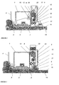
- FIG. 1 a screed 1 is shown behind which a spreader and a surface vibration device 13 is located.
- a dryer device which sucks the heating air of the screed heating by a Schuzziabsaugung 16 and blows BankLiteleitprofile 17 in the litter storage container 8.
- Under the metering roller 10 is a spreading agent cleaning device with two cleaning brushes 11 and integrated hot air dust extraction 19, which supplies the suctioned air by means of a blower 18 to a dust collector. This produces a dust-free, clean and dry litter material layer 15.
- a tracked surface vibrator 13 the scattered spreading material is shaken into the surface of the asphalt layer 14.
- the spreader is located directly behind screed 1 and before the pressure bars 6 and 7.
- an emulsion can be sprayed onto the litter to increase the adhesion force via a metering pump 23 and injection nozzles 21.
- the container 22 serves as a storage container and is designed as a module attachment.
- the application rates of metering roller 10 and the injection nozzle 21 are proportionally controlled in dependence on the operating speed of the paver.
- the desired values of spread rates of the metering roller 10 and the injection quantities of the nozzles 21 can be preset via a remote control.
- the actual value of the application rates is displayed via a digital display.
- FIG. 3 shows a screed 1, in which the scattering device between rammer 3 and Bohle 1 is arranged.
- the screed plate 2 of the screed 1 is formed so that the collection of litter material is ensured under the screed plate 2.
- the surface structure of the incorporated by the compression units vibrator 5 and pressure bars 6 and 7 grit can be adjusted independently by changing the metering slide 9 and metering roller 10 and the vibration frequency and amplitude of the compression units.
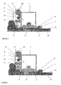
- FIG. 4 a spreader is shown, which is arranged between the front wall 4 and rammer 3 of the screed 1 as an add-on module.
- a spreader is shown, which is arranged between the front wall 4 and rammer 3 of the screed 1 as an add-on module.
- facilities are installed which make it possible to block the spreading of spreading material in the overlapping area.
- the device is suitable for every occurring screed broadening designed and can be widened just as it is known from screeds ago.
- Screed 1 shown has two rammers 3 and 24, between which a receiving space 25 is arranged for spreading material or in which the device is mounted. If the receiving space 25 is used as a filling space for spreading material, a distribution screw 26 is arranged above the receiving space 25. With the setting of the ram stroke of the two rammers 3 and 24 and the position of the rammer to each other, the strength of the spreading material layer 15 can be determined. This positioning can be finely adjusted by means of a linear adjustment 27. It is also possible to provide the spreader with broadening parts with which the working width as well as the screed 1 can be changed.
- FIG. 6 is arranged on the screed 1 as a device for fine metering a vibrating distributor bar 28 which is connected to a second vibration device 29.
- a vibrating distributor bar 28 which is connected to a second vibration device 29.
- the amount of scattering material to be distributed can be adjusted. It is also possible to run the vibratory distributor bar 28 as a conveyor belt distributor.
- FIG. 7 is a cross-section of an adjusting axis 30 rotatable and lockable vibration distribution bar 28 is shown, whose surface is provided with a profiling 31, whose structure is arranged in both directions.
- the adjustment axis 30 extends approximately parallel to the roadway transverse to the direction of travel.
- the vibration distribution bar 28 is rotatable about an axis designated z, which extends approximately in the direction of travel. It is also possible to run the vibratory distributor bar 28 as a conveyor belt distributor.
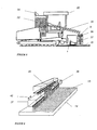
- FIG. 8 which represents an embodiment of the invention, the arrangement of a further storage container 33 for spreading material on a paver 32 is shown.
- the further reservoir 33 has a filler neck 34 for filling with grit.
- a screw conveyor 35 is arranged, the spreading material to a serving among other things as a reservoir 8 middle split spreader 36, which is attached to the screed 1, transported.
- a portion of this material to be spread is from the middle split spreader 36 in a left and a right split spreader 37, 38, which are each arranged below the middle split spreader 36, transported and distributed by these finely dosed as a spreading material layer 15.
- FIG. 9 a device is shown with adjustable in an adjustment 42 working width, the middle split spreader 36 are attached to the screed 1 and the left and the right split spreader 37, 38 on extension parts of the screed 1.
- the middle split spreader 36 is located above the left and right split spreaders 37, 38, wherein the middle split spreader 36, each with a partial length with the left and the right split spreader 37, 38 covered.
- the middle split spreader 36 finely dosed litter falls directly on the asphalt layer 14, in the covering areas, the litter falls from the middle split spreader 36 first in the left and right split spreader 37, 38, is distributed in these each transverse and then finely dosed from these immediately on the asphalt layer 14, so that a uniform grit layer 15 is made possible with variable roadway width.
- a middle split spreader 36 is shown in the upper part, which serves as a reservoir 8.
- this middle split spreader 36 is a distribution screw 26, which both distributes the spreading material in this middle split spreader 36 and pushes out of the open ends open on both sides; the grit pushed out of the ends open at both ends initially falls into a left and a right grit spreader 37, 38.
- the left and right split spreader 37, 38 are disposed below the central splitter spreader 36 and also have in their interior in each case a distributor screw 26, with the grit inside the grit spreader 37, 38 first is distributed across.
- the lateral split spreaders 37, 38 also serve as a reservoir 8, in which a predosing of the material to be spread takes place.
- a metering roller 10 is arranged in each case, with the aid of which a fine metering of the material to be grit located in the grit spreaders takes place.
- the fine-dosed grit from the middle splitter spreader 36 falls directly onto the asphalt layer 14, while in the covering areas between the middle grit spreader 36 with the lateral grit spreaders 37, 38 the finely dosed grit first falls into the lateral grit spreaders 37, 38.
- a fill level sensor 54 is arranged, which serves to monitor the amount of grit in each splitter spreader 36, 37, 38.
- the level sensors 54 are coupled to a control device, with the help of which, if necessary, the speed of the distributor screws 26 or the supply of grit to the central split spreader 36 can be changed.
- a sensor 57 is arranged on the middle split spreader 36, with which an angle of this central split spreader 36 can be determined by two axes each; this sensor 57 is also connected to the control device.
- the overlying middle split spreader 36 visible in his view.
- the grit conveyed by means of the upper auger 26 within the central grit spreader 36 falls into the left splitter spreader 37 at the end of the middle grit spreader 36, is distributed therein by means of the auger 26 disposed therein, finely metered by means of a metering roller 10 arranged below it and falls from there on a rotatable and lockable arranged baffle 51, of which the fine-dosed grit is passed to the asphalt layer 14 and forms a uniform grit layer 15 there.
- FIG. 12 shows a section through two superimposed split spreaders 36, 37 in their coverage area.
- a metering roller 10 is also arranged, which serves for fine metering of the material to be spread.
- an adjustable baffle 51 is arranged, which serves for the central region below the middle split spreader 36 for the distribution of the material to be spread on the asphalt layer 14. In the overlap area with the lower left splitter spreader 37, however, the grit is guided via the baffle 51 into the grit spreader 37, 38 underneath and redistributed therefrom.
Landscapes
- Engineering & Computer Science (AREA)
- Architecture (AREA)
- Civil Engineering (AREA)
- Structural Engineering (AREA)
- Road Paving Machines (AREA)
- Road Paving Structures (AREA)
- Road Repair (AREA)
- Compositions Of Macromolecular Compounds (AREA)
Description
- Die Erfindung betrifft einen Straßenfertiger mit einer Einbaubohle und einem Vorratsbehälter hinter der Einbaubohle, wobei der Vorratsbehälter einen Splittstreuer mit einer Dosierwalze aufweist, und wobei am Straßenfertiger ein weiterer Vorratsbehälter angeordnet ist, welcher über Einfüllstutzen mit Streugut befüllbar ist, wobei das Streugut von dem weiteren Vorratsbehälter zu dem als Vorratsbehälter dienenden Splittstreuer befördert wird.
- Aus dem Stand der Technik ist bekannt, dass zur Erhöhung der Anfangsgriffigkeit von neugebauten Asphaltstraßen Abstreumaterial direkt hinter der Einbaubohle oder zwischen ersten Walzengängen aufgebracht und mit Walzen in die noch verformungsfähige Asphaltschicht eingewalzt wird. Zur Erzielung eines gleichmäßigen hohen Reibbeiwertes sowie einer gleichmäßigen Oberflächenstruktur werden maschinelle Streueinrichtungen eingesetzt.
- Nach
DE 26 56 371 C2 ist eine Vorrichtung zum Verteilen von Materialien bekannt, die zur Erhöhung der Griffigkeit von Verkehrsflächen geeignet ist. Das Verteilergerät kann als Ein- oder Zweischeibenstreuer als Anbaugeräte an Walzen eingesetzt werden. Die Antriebsorgane dieser Streuer sind flache oder nach außen kegelförmig ansteigende runde Schleuderscheiben, die mit konstanter Drehzahl um eine vertikale Drehachse rotieren. Damit das Streumaterial tangential auf Scheibenumfangsgeschwindigkeit beschleunigt werden kann, sind auf der Scheibenoberseite Rippen aufgeschweißt, an denen die Splittkörner durch die Wirkung der Fliegkraft nach außen gleiten. Die Streubreite wird bei diesen Streuern durch die Abwurfgeschwindigkeit, die Abwurfhöhe, Anzahl der Scheiben und dem Luftwiderstand auf das geworfene Granulatteilchen bestimmt. Aufgrund der einfachen Bauweise, der geringen Störanfälligkeit, die bequemen Reinigungsmoglichkeiten und die hohe Flächenleistung hat dieses Verteilerprinzip eine große Anwendung in der Praxis gefunden. - Nachteilig bei dieser Art des Absplittens ist ein ungleichmäßiges Streubild, das mit einer hohen Überschussmenge an Streumaterial kompensiert werden muss.
- Nach
DE 36 39 575 A1 ,DE 41 05 045 A1 ,DE 37 00 505 C2 undDE 42 22 701 A1 sind Vorrichtungen bekannt, die sich mit der Verbesserung des Streubildes von Schleuderscheibenstreuer befassen, ohne jedoch die Charakteristik des Streubildes wesentlich zu verändern. Auch das Streuen einer Überschussmenge zu einer gleichmäßigen Fahrbahnabdeckung ist keine geeignete Lösung, da sich ein großer Anteil der ausgestreuten Splittmengen am Fahrbahnrand ablagert. Der nicht gebundene Splitt muss dann mit Hilfe von Saugkehrmaschinen wieder aufgenommen werden, um die Fahrsicherheit zu gewährleisten. - Aus
FR 79 30 414 - In
DE-GM 73 29 587 ist ein Freifall-Splittstreuer mit Dosierwalze und Vorratsbehälter beschrieben, der als Anbaugerät an einer Straßenwalze angeordnet ist. Zur Feinregulierung der auszubringenden Streugutmenge ist die Dosierwalze separat angetrieben und kann während des Einsatzes vom Walzenfahrer verstellt werden. Nachteilig ist dabei, dass für die gesamte Breite der Einbaubohle des Straßenfertigers mehrere Walzbahnen mit jeweils neuen Ansätzen erforderlich sind, die eine Überlappung von Streugut erforderlich machen, womit keine gleichmäßige Streucharakteristik erreicht wird. - Aus
DE 41 18 997 A1 ist ein selbstfahrender Splittstreuer mit einem Aufnahmebehälter bekannt, der zur Erzielung eines gleichmäßigen Splittabwurfes in genau dosierter Menge eine Rüttelrinne als Abwurfvorrichtung aufweist, die unterhalb eines Abgabespaltes am Vorratsbehälter befestigt ist. Die Rüttelrinne besteht aus einem Mittelteil mit verstellbaren Endabschnitten was eine verstellbare Streubreite ermöglicht. Mittels eines Neigungssensors wird die Rüttelrinne unabhängig von der Neigung der Fahrbahn in eine vorgegebene Solllage gehalten. Nachteilig ist dabei, dass die Streugenauigkeit, sowohl hinsichtlich der pro Quadratmeter Fahrbahn ausgetragene Splittmenge, als auch hinsichtlich der gleichmäßigen Splittverteilung, erheblich von der Beschaffenheit des Streugutes abhängt. Insbesondere die Korngrößen-Verteilung, die Feuchtigkeit und Temperatur des Streugutes sowie seine Öberflächenbeschaffenheit beeinflussen das Streubild. - Nach
DE 195 02 281 C2 ist ein selbstfahrender Splittstreuer bekannt, der quer zur Fahrtrichtung eine in der Arbeitsbreite verstellbare Streubohle mit einem Schwingungserreger aufweist und den Splitt zu mindestens einer Abwurfskante befördert und ihn dort abwirft. Zur Erzielung einer verbesserten Korngrößen-Verteilung besitzt die Streubohle an der splitttragenden Oberfläche zumindest zur Abwurfkante hin eine wellenähnliche Profilierung. Des Weiteren weist die Streubohle eine Mengenmesseinrichtung auf, die Splittteilchen berührungslos zählt. - Nachteilig bei allen vorgenannten Vorrichtungen zum Splittstreuen ist, dass das Einwalzen des Splittes frühestens nach dem ersten Walzengang erfolgt und nicht zum optimalen Zeitpunkt direkt während des Mischguteinbaus durch den Straßenfertiger. Dies führt dazu, dass nicht alle Splittkörner mit der erforderlichen Haftung in die Asphaltdeckschicht eingearbeitet werden, was die Qualität der abgesplitteten Straßentiberfläche hinsichtlich der Anfangsrauigkeit stark reduziert und durch losen Splitt vermehrt Schäden, insbesondere an Windschutzscheiben, entstehen.
- Nach
DE 14 09 840 ist ein Verfahren zum Aufbringen von Abstreumaterial auf bituminöse Fahrbahndecken bekannt, bei dem Abstreumaterial durch Druckluft oder durch Schleuderkraft dicht hinter dem Dickenfertiger in den Reifen, weichen bituminösen Fahrbahnbelag in einem Arbeitsvorgang verteilt und eingedrückt wird, wobei der Schrift, zu entnehmen ist, dass dieses Einbringen durch eine oder mehrere Spritz- oder Schleuderdüsen von Hand oder maschinell quer über die Deckenoberflächen und herlaufend geführt werden sollen. - Nachteilig ist dabei, dass mit diesem Verfahren eine gleichmäßige Verteilung von Streugut nicht möglich ist.
- Nach
DE 27 40 667 ist eine Vorrichtung zur Erneuerung von Fahrbahndicken bekannt, bei der bedarfsweise an eine Glättbohle ein Splittstreuer angehängt sein kann, der über Räder in der gleichen Spur wie die Glättbohle geführt ist und wobei die Dosierung des Splittmaterials über Drehbewegung von Rädern erfolgt. - Nachteilig ist dabei, dass zur Verteilung des Splittes ein gesondertes Gerät erforderlich ist und das eine Steuerung der Dosierung der Streumenge nicht möglich ist.
- Ferner ist nach
DE 20 27 297 A eine Gussasphalt-Einbauvorrichuhg mit einer Einbaubohle und einem Vorratsbehälter bekannt. Bei dieser Vorrichtung weist der Vorratsbehälter einen Splittstreuer mit einer Dosierwalze auf. Die Vorrichtung enthält einen weiteren Vorratsbehälter, welcher über Einfüllstutzen mit Streugut befüllbar ist, wobei das Streugut von dem weiteren Vorratsbehälter zu dem als Vorratsbehälter dienenden Splittstreuer befördert wird. Eine gleichmäßige Streugutschicht über die gesamte Breite der Streuvorrichtung kann damit nicht erzeugt werden. - Der Erfindung liegt die Aufgabe zugrunde, ein eine Vorrichtung der eingangs genannten Art anzugeben, mit der eine gleichmäßige Streugutschicht über die gesamte Breite der Streuvorrichtung ermöglicht wird.
- Erfindungsgemäß wird die Aufgabe mit einer Vorrichtung, welche die in Anspruch 1 angegebenen Merkmale enthält, gelöst.
- Vorteilhafte Ausgestaltungen sind in den Unteransprüchen angegeben.
- Die Erfindung wird im Folgenden anhand der beigefügten Zeichnungen näher erläutert. In den zugehörigen Zeichnungen zeigen:
- Figur 1
- eine hinter der Einbaubohle angeordnete Vorrichtung mit separaten Oberflächenvibrator sowie einer Trockner- und Streumittel-Reinigungseinrichtung mit integrierter HeizluftStaubabsaugung,
- Figur 2
- eine zwischen Einbaubohle und Pressleiste angeordnete Vorrichtung mit einer Einrichtung zum Vorbituminieren des Streumaterials,
- Figur 3
- eine zwischen Stampfer und Einbaubohle angeordnete Vorrichtung,
- Figur 4
- eine vor Stampfer und Einbaubohle angeordnete Vorrichtung,
- Figur 5
- eine zwischen zwei Stampfer vor der Einbaubohle angeordnete Vorrichtung,
- Figur 6
- eine Vorrichtung mit einem Vibrationsverteilerbalken zur Feindosierung
- Figur 7
- zwei Querschnitte eines Vibrationsverteilerbalkens,
- Figur 8
- eine Schnittdarstellung einer Ausführungsform der Erfindung mit einem weiteren Vorratsbehälter, einer Förderschnecke und Splittstreuern,
- Figur 9
- eine zugehörige räumliche systematische Darstellung,
- Figur 10
- eine zugehörige systematische Rückansicht,
- Figur 11
- eine Schnittdarstellung erfindungsgemäßer Splittstreuer und
- Figur 12
- eine zugehörige weitere Schnittdarstellung.
- Die
Figuren 1-7 stellen keine Ausführungsformen der Erfindung dar. Es handelt sich dabei um Beispiele, die das Verständnis der Erfindung erleichtern. - In
Figur 1 ist eine Einbaubohle 1 dargestellt, hinter der sich eine Streuvorrichtung und eine Oberflächen-Vibrationseinrichtung 13 befindet. Mit Hilfe einer Trocknereinrichtung, welche die Heizluft der Bohlenheizung durch eine Heizluftabsaugung 16 ansaugt und über Heizluftleitprofile 17 in den Streumaterial-Vorratsbehälter 8 bläst. Unter der Dosierwalze 10 befindet sich eine Streumittel-Reinigungseinrichtung mit zwei Reinigungsbürsten 11 und integrierter Heizluft-Staubabsaugung 19, die mittels eines Gebläses 18 die abgesaugte Luft einem Staubabscheider zuführt. Damit wird eine staubfreie, saubere und trockene Streumaterialschicht 15 erzeugt. Mit Hilfe eines nachgeführten Oberflächenvibrators 13 wird das verteilte Streugut in die Oberfläche der Asphaltschicht 14 eingerüttelt. - In
Figur 2 ist die Streuvorrichtung direkt hinter Einbaubohle 1 und vor den Pressleisten 6 und 7 angeordnet. Je nach Zustand des verwendeten Streumaterials kann zur Klebkrafterhöhung über eine Dosierpumpe 23 und Einspritzdüsen 21 eine Emulsion auf das Streugut gesprüht werden. Der Behälter 22 dient hierzu als Vorratsbehälter und ist als Aufsatzmodul konzipiert. Die Ausbringmengen von Dosierwalze 10 und der Einspritzdüse 21 werden in Abhängigkeit von der Arbeitsgeschwindigkeit des Straßenfertigers proportional geregelt. Über eine Fernbedienung lassen sich die Sollwerte von Streumengen der Dosierwalze 10 und die Einspritzmengen der Düsen 21 vorgeben. Der Istwert der Ausbringmengen wird über eine Digitalanzeige dargestellt. -
Figur 3 zeigt eine Einbaubohle 1, bei der die Streuvorrichtung zwischen Stampfer 3 und Bohle 1 angeordnet ist. Das Glättblech 2 der Einbaubohle 1 ist so ausgebildet, dass der Einzug von Streumaterial unter das Glättblech 2 gewährleistet ist. Die Oberflächenstruktur des durch die Verdichtungsaggregate Vibrator 5 sowie Pressleisten 6 und 7 eingearbeiteten Streuguts lassen sich durch Veränderung von Dosierschieber 9 und Dosierwalze 10 sowie der Schwingfrequenz und Schwingamplitude der Verdichtungsaggregate unabhängig voneinander einstellen. - In
Figur 4 ist eine Streuvorrichtung dargestellt, die zwischen Vorderwand 4 und Stampfer 3 der Einbaubohle 1 als Anbaumodul angeordnet ist. Bei Bohlen mit verstellbarer Einbaubreite sind Einrichtungen angebracht, mit denen es möglich ist, im Überlappungsbereich das Ausbringen von Streugut zu sperren. Die Vorrichtung ist passend für jede vorkommende Bohlenverbreiterung konzipiert und lässt sich genauso verbreitern, wie dies von Einbaubohlen her bekannt ist. - Die in
Figur 5 dargestellte Einbaubohle 1 verfügt über zwei Stampfer 3 und 24, zwischen denen ein Aufnahmeraum 25 für Streugut angeordnet ist oder in dem die Vorrichtung montiert wird. Wird der Aufnahmeraum 25 als Füllraum für Streugut verwendet, ist oberhalb des Aufnahmeraums 25 eine Verteilerschnecke 26 angeordnet. Mit der Einstellung des Stampferhubes der beiden Stampfer 3 und 24 und der Position der Stampfer zueinander lässt sich die Stärke der Streugutschicht 15 bestimmen. Diese Positionierung kann mittels einer Linearverstellung 27 feinfüllig eingestellt werden.
Es ist auch möglich, die Streuvorrichtung mit Verbreiterungsteilen zu versehen, mit denen die Arbeitsbreite ebenso wie die der Einbaubohle 1 verändert werden kann. - In
Figur 6 ist an der Einbaubohle 1 als Einrichtung zur Feindosierung ein Vibrationsverteilerbalken 28 angeordnet, der mit einer zweiten Vibrationseinrichtung 29 verbunden ist. In Abhängigkeit der Stellung des Dosierschiebers 9 und der Stärke der Vibration der zweiten Vibrationseinrichtung 29 lässt sich die Menge des zu verteilenden Streugutes einstellen.
Es ist auch möglich, den Vibrationsverteilerbalken 28 als Förderbandverteiler ausführen. -
Figur 7 ist ein Querschnitt eines um eine Verstellachse 30 drehbaren und feststellbaren Vibrationsverteilerbalkens 28 dargestellt, dessen Oberfläche mit einer Profilierung 31 versehen ist, deren Struktur in beide Richtung angeordnet ist. Die Verstellachse 30 verläuft etwa parallel zur Fahrbahn quer zur Fahrtrichtung. Darüber hinaus ist der Vibrationsverteilerbalken 28 um eine mit z bezeichnete Achse, die etwa in Fahrtrichtung verläuft drehbar.
Es ist auch möglich, den Vibrationsverteilerbalken 28 als Förderbandverteiler ausführen. - In
Figur 8 , die eine Auführungsform der Erfindung darstellt, ist die Anordnung eines weiteren Vorratsbehälters 33 für Streugut an einem Straßenfertiger 32 dargestellt. Der weitere Vorratsbehälter 33 weist einen Füllstutzen 34 zum Befüllen mit Streugut auf. An dem weiteren Vorratsbehälter 33 ist eine Förderschnecke 35 angeordnet, die Streugut zu einem unter anderem als Vorratsbehälter 8 dienenden mittleren Splittstreuer 36, welcher an der Einbaubohle 1 befestigt ist, befördert. Ein Teil dieses Streugutes wird vom mittleren Splittstreuer 36 in einen linken und einen rechten Splittstreuer 37, 38, welche jeweils unterhalb des mittleren Splittstreuer 36 angeordnet sind, befördert und von diesen feindosiert als Streugutschicht 15 verteilt. - In
Figur 9 ist eine Vorrichtung mit in einer Verstellrichtung 42 verstellbarer Arbeitsbreite dargestellt, wobei der mittlere Splittstreuer 36 an der Einbaubohle 1 und der linke und der rechte Splittstreuer 37, 38 an Ausfahrteilen der Einbaubohle 1 befestigt sind. Der mittlere Splittstreuer 36 befindet sich oberhalb des linken und des rechten Splittstreuers 37, 38, wobei sich der mittlere Splittstreuer 36 mit jeweils einer Teillänge mit dem linken und dem rechten Splittstreuer 37, 38 überdeckt. Im mittleren Bereich des mittleren Splittstreuers 36 fällt feindosiertes Streugut unmittelbar auf die Asphaltschicht 14, in den Überdeckungsbereichen fällt das Streugut vom mittleren Splittstreuer 36 zunächst in den linken und den rechten Splittstreuer 37, 38, wird in diesen jeweils querverteilt und fällt von diesen anschließend feindosiert unmittelbar auf die Asphaltschicht 14, so dass eine gleichmäßige Streugutschicht 15 bei variabler Fahrbahnbreite ermöglicht wird. - Bei der in
Figur 10 dargestellten Rückansicht ist im oberen Bereich ein mittlerer Splittstreuer 36 dargestellt, der als Vorratsbehälter 8 dient. In diesem mittleren Splittstreuer 36 befindet sich eine Verteilerschnecke 26, welche sowohl das Streugut in diesem mittleren Splittstreuer 36 verteilt als auch aus den beidseitig offenen ausgebildeten Enden herausdrückt; das aus den beidseitig offenen Enden herausgedrückte Streugut fällt zunächst in einen linken und in einen rechten Splittstreuer 37, 38. Der linke und der rechte Splittstreuer 37, 38 sind unterhalb des mittleren Splittstreuers 36 angeordnet und weisen in ihrem Inneren ebenfalls jeweils eine Verteilerschnecke 26 auf, mit der innerhalb der Splittstreuer 37, 38 das Streugut zunächst quer verteilt wird. Die seitlichen Splittstreuer 37, 38 dienen ebenfalls als Vorratsbehälter 8, in welchem eine Vordosierung des Streugutes erfolgt. Im unteren Bereich der Splittstreuer 36, 37, 38 ist jeweils eine Dosierwalze 10 angeordnet, mit deren Hilfe eine Feindosierung des in den Splittstreuern befindlichen Streugutes erfolgt. Zwischen den seitlichen Splittstreuern 37, 38 fällt das feindosierte Streugut vom mittleren Splittstreuer 36 unmittelbar auf die Asphaltschicht 14, während in den Überdeckungsbereichen zwischen dem mittleren Splittstreuer 36 mit den seitlichen Splittstreuern 37, 38 das feindosierte Streugut zunächst in die seitlichen Splittstreuer 37, 38 fällt. An jedem der Splittstreuer 36, 37, 38 ist jeweils ein Füllstandssensor 54 angeordnet, der dazu dient, die Streugutmenge in jedem Splittstreuer 36, 37, 38 zu überwachen. Die Füllstandssenoren 54 sind mit einer Steuerungseinrichtung gekoppelt, mit deren Hilfe bei Bedarf die Drehzahl der Verteilerschnecken 26 bzw. die Zufuhr von Streugut zum mittleren Splittstreuer 36 geändert werden können. Am mittleren Splittstreuer 36 ist darüber hinaus ein Sensor 57 angeordnet, mit dem ein Winkel dieses mittleren Splittstreuers 36 um jeweils zwei Achsen bestimmt werden kann; dieser Sensor 57 ist ebenfalls mit der Steuerungseinrichtung verbunden. - Bei dem in
Figur 11 dargestellten Schnitt durch den linken Splittstreuer 37 ist der darüber liegende mittlere Splittstreuer 36 in seiner Ansicht sichtbar. Das mittels der oberen Verteilerschnecke 26 innerhalb des mittleren Splittstreuers 36 beförderte Streugut fällt am Ende des mittleren Splittstreuers 36 in den darunter liegenden linken Splittstreuer 37, wird in diesem mittels der darin angeordneten Verteilerschnecke 26 querverteilt, mittels einer darunter angeordneten Dosierwalze 10 feindosiert und fällt von dort auf ein verdrehbar und feststellbar angeordnetes Leitblech 51, von welchem das feindosierte Streugut auf die Asphaltschicht 14 geleitet wird und dort eine gleichmäßige Streugutschicht 15 bildet. -
Figur 12 zeigt einen Schnitt durch zwei übereinander angeordnete Splittstreuer 36, 37 in deren Überdeckungsbereich. Am unteren Rand des mittleren Splittstreuers 36 ist ebenfalls eine Dosierwalze 10 angeordnet, die zur Feindosierung des Streugutes dient. Unterhalb dieser Dosierwalze 10 ist ebenfalls ein verstellbares Leitblech 51 angeordnet, welches für den mittleren Bereich unter dem mittleren Splittstreuer 36 zur Verteilung des Streugutes auf die Asphaltschicht 14 dient. Im Überdeckungsbereich mit dem unteren, linken Splittstreuer 37 wird jedoch das Streugut über das Leitblech 51 in die darunter liegenden Splittstreuer 37, 38 geleitet und von diesen weiterverteilt. -
- 1 Einbaubohle
- 2 Glättblech
- 3 Stampfer
- 4 Vorderwand
- 5 Vibrator
- 6 Pressleiste I
- 7 Pressleiste II
- 8 Vorratsbehälter
- 9 Dosierschieber
- 10 Dosierwalze
- 11 Reinigungsbürsten
- 12 erste Vibrationseinrichtung
- 13 Oberflächenglätter mit Vibration
- 14 Asphaltschicht
- 15 Streugutschicht
- 16 Heizluftabsaugung
- 17 Heizluftleitprofile
- 18 Gebläse
- 19 Heizluftstaubabsaugung
- 20 Abscheider
- 21 Einspritzdüse
- 22 Behälter
- 23 Dosierpumpe
- 24 Stampfer
- 25 Aufnahmeraum
- 26 Verteilerschnecke
- 27 Linearverstellung
- 28 Vibrationsverteilerbalken
- 29 zweite Vibrationseinrichtung
- 30 Verstellachse
- 31 Profilierung
- 32 Straßenfertiger
- 33 weiterer Vorratsbehälter
- 34 Einfüllstutzen
- 35 Förderschnecke
- 36 mittlerer Splittstreuer
- 37 linker Splittstreuer
- 38 rechter Splittstreuer
- 42 Verstellrichtung
- 51 Leitblech
- 54 Füllstandssensor
- 57 Sensor
Claims (3)
- Straßenfertiger mit einer Einbaubohle (1) und einem Vorratsbehälter (8) in Fahrtrichtung hinter der Einbaubohle (1), wobei der Vorratsbehälter (8) einen Splittstreuer mit einer Dosierwalze (10) aufweist, und wobei am Straßenfertiger ein weiterer Vorratsbehälter (33) angeordnet ist, welcher über Einfüllstutzen (34) mit Streugut befüllbar ist, wobei das Streugut von dem weiteren Vorratsbehälter (33) zu dem als Vorratsbehälter dienenden Splittstreuer befördert wird, dadurch gekennzeichnet,- dass der Splittstreuer ein mittlerer Splittstreuer (36) ist und darunter jeweils versetzt ein linker Splittstreuer (37) und ein rechter Splittstreuer (38) angeordnet sind,- dass jeder dieser Splittstreuer (36, 37, 38) zur Vordosierung des Streugutes mindestens eine Verteilerschnecke (26) beinhaltet, wobei die Verteilerschnecke (26) des mittleren Splittstreuers (36) Streugut in oder auf den linken und den rechten Splittstreuer (37, 38) befördert und die Verteilerschnecken (26) des linken und des rechten Splittstreuers (37, 38) das Streugut quer verteilen,- dass eine Förderschnecke (35) zum Transport des Streuguts von dem weiteren Vorratsbehälter (33) zu dem als Vorratsbehälter dienenden mittleren Splittstreuer (36) angeordnet ist,- dass unterhalb jedes Splittstreuers (36, 37, 38) eine Einrichtung zur Feindosierung des Streugutes mit jeweils einer Dosierwalze (10) angeordnet ist und- dass unterhalb jeden Splittstreuers (36, 37, 38) jeweils ein Leitblech (51) mit verstellbaren Winkeln angeordnet ist.
- Straßenfertiger nach Anspruch 1, dadurch gekennzeichnet, dass am mittleren Splittstreuer (36) ein Sensor (57) zur Winkelmessung um zwei Achsen des mittleren Splittstreuers (36) angeordnet ist und dass eine Regeleinrichtung zur Einstellung der Winkel der Leitbleche (51) in und quer zur Fahrtrichtung des Fertigers (32) angeordnet ist.
- Straßenfertiger nach Anspruch 1 oder 2, dadurch gekennzeichnet, dass für jeden Splittstreuer (36, 37, 38) jeweils ein Füllstandssensor (54) angeordnet ist.
Applications Claiming Priority (2)
| Application Number | Priority Date | Filing Date | Title |
|---|---|---|---|
| DE10149363 | 2001-10-06 | ||
| DE10149363A DE10149363A1 (de) | 2001-10-06 | 2001-10-06 | Verfahren und eine Vorrichtung zum Einbringen von Streugut in eine Asphaltschicht |
Publications (3)
| Publication Number | Publication Date |
|---|---|
| EP1300517A2 EP1300517A2 (de) | 2003-04-09 |
| EP1300517A3 EP1300517A3 (de) | 2004-01-28 |
| EP1300517B1 true EP1300517B1 (de) | 2008-04-09 |
Family
ID=7701647
Family Applications (1)
| Application Number | Title | Priority Date | Filing Date |
|---|---|---|---|
| EP02022177A Expired - Lifetime EP1300517B1 (de) | 2001-10-06 | 2002-10-04 | Vorrichtung zum Einbringen von Streugut in eine Asphaltschicht |
Country Status (5)
| Country | Link |
|---|---|
| EP (1) | EP1300517B1 (de) |
| AT (1) | ATE391811T1 (de) |
| DE (2) | DE10149363A1 (de) |
| DK (1) | DK1300517T3 (de) |
| ES (1) | ES2305167T3 (de) |
Cited By (2)
| Publication number | Priority date | Publication date | Assignee | Title |
|---|---|---|---|---|
| EP2944722A1 (de) | 2014-05-12 | 2015-11-18 | TPA GmbH | Verfahren zur Herstellung einer Fahrbahndecke |
| WO2025242525A1 (de) * | 2024-05-23 | 2025-11-27 | Streumaster Maschinenbau GmbH | Querverteilungsvorrichtung und streumaschine |
Families Citing this family (2)
| Publication number | Priority date | Publication date | Assignee | Title |
|---|---|---|---|---|
| FR2899909B1 (fr) * | 2006-04-13 | 2008-07-04 | Secmair Sa | Dispositif a gabarit variable pour l'epandage de gravillons sur une chaussee |
| DE102021113467A1 (de) | 2021-05-25 | 2022-12-01 | VFHG Haus- und Grundstücks GmbH | Fahrzeug zur Sanierung von Pflaster- oder Plattenbelägen |
Family Cites Families (13)
| Publication number | Priority date | Publication date | Assignee | Title |
|---|---|---|---|---|
| DE7329587U (de) | 1973-12-06 | Richard Mayer & Co Bauunternehmung | Vorrichtung zum Austragen von Straßen belagmatenal | |
| DE1409840A1 (de) * | 1961-11-01 | 1969-01-30 | Anton Scheuerer | Verfahren zum Aufbringen von Abstreumaterial auf bituminoese Fahrbahndecken |
| DE2027297A1 (de) * | 1970-06-03 | 1971-12-16 | Deutsche Asphalt GmbH, 6000 Frank fürt | Gußasphalt Einbauvorrichtung |
| FR2231815B1 (de) * | 1973-05-30 | 1976-06-11 | Screg | |
| DE2556371C2 (de) | 1975-12-15 | 1986-01-16 | Volker O. Prof. Dr.Med. 8012 Ottobrunn Lang | Beatmungskopf für Durchspülsysteme mit Kondenswasser-Eliminationsautomatik |
| DE2740667A1 (de) * | 1977-09-09 | 1979-03-15 | Voegele Ag J | Verfahren und vorrichtung zur erneuerung von beschaedigten fahrbahn- deckschichten |
| DE3639575A1 (de) | 1986-11-20 | 1988-06-01 | Weiste & Co Accord Landmasch | Maschine zum ausbringen von duenger oder anderen granulatfoermigen stoffen |
| DE3700505C2 (de) | 1987-01-09 | 1995-02-09 | Schmidt Alfred Ing Gmbh | Einrichtung zur Streugutkontrolle an einem Streugerät für den Winterstraßendienst |
| DE3904117A1 (de) * | 1989-02-11 | 1990-08-16 | Schoelkopf Fahrbahndecken Recy | Strassenbaumaschine zum erneuern des deckenbelages einer fahrbahn oder dgl. |
| DE4105045A1 (de) | 1991-01-18 | 1992-07-23 | Amazonen Werke Dreyer H | Verfahren zum einstellen der dosierorgane einer verteilmaschine |
| DE4118997A1 (de) * | 1991-06-08 | 1992-12-10 | Schoelkopf Fahrbahndecken Recy | Splittstreuer |
| DE4222701C2 (de) | 1992-07-10 | 1997-05-22 | Amazonen Werke Dreyer H | Elektronische Anzeigevorrichtung für einen Zentrifugalstreuer |
| DE19843193A1 (de) * | 1998-09-15 | 2000-03-30 | Mannesmann Ag | Verfahren zur Herstellung eines mit einem Bindemittel umhüllten Abstreusplitts |
-
2001
- 2001-10-06 DE DE10149363A patent/DE10149363A1/de not_active Withdrawn
-
2002
- 2002-10-04 DK DK02022177T patent/DK1300517T3/da active
- 2002-10-04 ES ES02022177T patent/ES2305167T3/es not_active Expired - Lifetime
- 2002-10-04 EP EP02022177A patent/EP1300517B1/de not_active Expired - Lifetime
- 2002-10-04 DE DE50212053T patent/DE50212053D1/de not_active Expired - Lifetime
- 2002-10-04 AT AT02022177T patent/ATE391811T1/de active
Cited By (2)
| Publication number | Priority date | Publication date | Assignee | Title |
|---|---|---|---|---|
| EP2944722A1 (de) | 2014-05-12 | 2015-11-18 | TPA GmbH | Verfahren zur Herstellung einer Fahrbahndecke |
| WO2025242525A1 (de) * | 2024-05-23 | 2025-11-27 | Streumaster Maschinenbau GmbH | Querverteilungsvorrichtung und streumaschine |
Also Published As
| Publication number | Publication date |
|---|---|
| ATE391811T1 (de) | 2008-04-15 |
| EP1300517A2 (de) | 2003-04-09 |
| ES2305167T3 (es) | 2008-11-01 |
| DE50212053D1 (de) | 2008-05-21 |
| EP1300517A3 (de) | 2004-01-28 |
| DK1300517T3 (da) | 2008-08-04 |
| DE10149363A1 (de) | 2003-04-17 |
Similar Documents
| Publication | Publication Date | Title |
|---|---|---|
| DE2850344A1 (de) | Verfahren und vorrichtung zum abtragen und neubeschichten von strassendecken | |
| EP3095916B1 (de) | Verfahren zur bankettstabilisierung, fahrwerk zur durchführung desselben und spezial-streuwagen | |
| EP3019663A1 (de) | Abgabevorrichtung für verfüllmaterial | |
| EP1300517B1 (de) | Vorrichtung zum Einbringen von Streugut in eine Asphaltschicht | |
| EP2215306B1 (de) | Fahrbare vorrichtung für das ausbringen von füllgut auf einem kunstrasenplatz | |
| DE69102046T2 (de) | Strassenfahrzeug zum Verteilen von Materialien bei der Wiederherstellung von Strassen, mit integrierten Walzen. | |
| DE1784673B1 (de) | Fahrbares Streugerät zum Streuen von k¦rnigem Streugut | |
| DE69001973T2 (de) | Ausziehbare Bohle zum Verdichten und Fertigen von Strassendeckenschichten mit Spritzvorrichtung für flüssiges Bindemittel. | |
| WO1981003352A1 (fr) | Procede et dispositif pour l'enlevement du revetement d'une route et la pose d'un nouveau revetement | |
| EP1073798B1 (de) | Vorrichtung zum bearbeiten von fahrbahnen | |
| DE4118997A1 (de) | Splittstreuer | |
| DE2556547A1 (de) | Randstreifenfertiger | |
| DE19845083B4 (de) | Verfahren und Vorrichtung zur Verteilung von Taumitteln | |
| DE1784763A1 (de) | Vorrichtung zum Streuen von insbesondere Splitt oder Sand im Zuge des Strassenbaues od.dgl. | |
| DE2453748A1 (de) | Strassenfertiger | |
| DE60023767T2 (de) | Vibrierender Strassenfertiger | |
| DE202011051588U1 (de) | Vorrichtung zum maschinellen Einbau von halbstarren Belagschichten | |
| AT523794B1 (de) | Streuvorrichtung | |
| EP1873313A2 (de) | Strassenfertiger und Verfahren zum Herstellen eines Banketts in Rückwärtsfahrt | |
| EP0497755B1 (de) | Verfahren zur Herstellung von dünnen Decken auf Bodenflächen, insbesondere Verkehrsflächen | |
| DE2555216A1 (de) | Strassenfertiger zum einbau von fahrbahndecken | |
| DE2835188A1 (de) | Schleppverteiler zum einbringen von strassenbaumischgut - insbesondere von bituminoesem kaltmischgut - in vertiefungen des planums, vorzugsweise in spurrillen von fahrbahndecken | |
| AT301601B (de) | Streugerät für körnige Feststoffe | |
| DE19953234B4 (de) | Kastenstreuer | |
| CH645943A5 (en) | Method and device for removing and recoating roadway coverings |
Legal Events
| Date | Code | Title | Description |
|---|---|---|---|
| PUAI | Public reference made under article 153(3) epc to a published international application that has entered the european phase |
Free format text: ORIGINAL CODE: 0009012 |
|
| AK | Designated contracting states |
Kind code of ref document: A2 Designated state(s): AT BE BG CH CY CZ DE DK EE ES FI FR GB GR IE IT LI LU MC NL PT SE SK TR Designated state(s): AT BE BG CH CY CZ DE DK EE ES FI FR GB GR IE IT LI LU MC NL PT SE SK TR |
|
| AX | Request for extension of the european patent |
Extension state: AL LT LV MK RO SI |
|
| PUAL | Search report despatched |
Free format text: ORIGINAL CODE: 0009013 |
|
| AK | Designated contracting states |
Kind code of ref document: A3 Designated state(s): AT BE BG CH CY CZ DE DK EE ES FI FR GB GR IE IT LI LU MC NL PT SE SK TR |
|
| AX | Request for extension of the european patent |
Extension state: AL LT LV MK RO SI |
|
| 17P | Request for examination filed |
Effective date: 20040717 |
|
| AKX | Designation fees paid |
Designated state(s): AT BE BG CH CY CZ DE DK EE ES FI FR GB GR IE IT LI LU MC NL PT SE SK TR |
|
| GRAP | Despatch of communication of intention to grant a patent |
Free format text: ORIGINAL CODE: EPIDOSNIGR1 |
|
| RTI1 | Title (correction) |
Free format text: APPARATUS FOR INCORPORATING GRANULAR MATERIAL IN AN ASPHALT LAYER |
|
| GRAS | Grant fee paid |
Free format text: ORIGINAL CODE: EPIDOSNIGR3 |
|
| GRAA | (expected) grant |
Free format text: ORIGINAL CODE: 0009210 |
|
| AK | Designated contracting states |
Kind code of ref document: B1 Designated state(s): AT BE BG CH CY CZ DE DK EE ES FI FR GB GR IE IT LI LU MC NL PT SE SK TR |
|
| REG | Reference to a national code |
Ref country code: GB Ref legal event code: FG4D Free format text: NOT ENGLISH |
|
| REG | Reference to a national code |
Ref country code: CH Ref legal event code: EP |
|
| REG | Reference to a national code |
Ref country code: IE Ref legal event code: FG4D Free format text: LANGUAGE OF EP DOCUMENT: GERMAN |
|
| REF | Corresponds to: |
Ref document number: 50212053 Country of ref document: DE Date of ref document: 20080521 Kind code of ref document: P |
|
| REG | Reference to a national code |
Ref country code: SE Ref legal event code: TRGR |
|
| REG | Reference to a national code |
Ref country code: DK Ref legal event code: T3 |
|
| PG25 | Lapsed in a contracting state [announced via postgrant information from national office to epo] |
Ref country code: PT Free format text: LAPSE BECAUSE OF FAILURE TO SUBMIT A TRANSLATION OF THE DESCRIPTION OR TO PAY THE FEE WITHIN THE PRESCRIBED TIME-LIMIT Effective date: 20080909 Ref country code: FI Free format text: LAPSE BECAUSE OF FAILURE TO SUBMIT A TRANSLATION OF THE DESCRIPTION OR TO PAY THE FEE WITHIN THE PRESCRIBED TIME-LIMIT Effective date: 20080409 Ref country code: BG Free format text: LAPSE BECAUSE OF FAILURE TO SUBMIT A TRANSLATION OF THE DESCRIPTION OR TO PAY THE FEE WITHIN THE PRESCRIBED TIME-LIMIT Effective date: 20080709 |
|
| REG | Reference to a national code |
Ref country code: ES Ref legal event code: FG2A Ref document number: 2305167 Country of ref document: ES Kind code of ref document: T3 |
|
| REG | Reference to a national code |
Ref country code: IE Ref legal event code: FD4D |
|
| EN | Fr: translation not filed | ||
| PG25 | Lapsed in a contracting state [announced via postgrant information from national office to epo] |
Ref country code: CZ Free format text: LAPSE BECAUSE OF FAILURE TO SUBMIT A TRANSLATION OF THE DESCRIPTION OR TO PAY THE FEE WITHIN THE PRESCRIBED TIME-LIMIT Effective date: 20080409 Ref country code: IE Free format text: LAPSE BECAUSE OF FAILURE TO SUBMIT A TRANSLATION OF THE DESCRIPTION OR TO PAY THE FEE WITHIN THE PRESCRIBED TIME-LIMIT Effective date: 20080409 |
|
| PLBE | No opposition filed within time limit |
Free format text: ORIGINAL CODE: 0009261 |
|
| STAA | Information on the status of an ep patent application or granted ep patent |
Free format text: STATUS: NO OPPOSITION FILED WITHIN TIME LIMIT |
|
| PG25 | Lapsed in a contracting state [announced via postgrant information from national office to epo] |
Ref country code: SK Free format text: LAPSE BECAUSE OF FAILURE TO SUBMIT A TRANSLATION OF THE DESCRIPTION OR TO PAY THE FEE WITHIN THE PRESCRIBED TIME-LIMIT Effective date: 20080409 |
|
| ET | Fr: translation filed | ||
| REG | Reference to a national code |
Ref country code: FR Ref legal event code: EERR Free format text: CORRECTION DE BOPI 09/05 - BREVETS EUROPEENS DONT LA TRADUCTION N A PAS ETE REMISE A L INPI. IL Y A LIEU DE SUPPRIMER : LA MENTION DE LA NON-REMISE. LA REMISE DE LA TRADUCTION EST PUBLIEE DANS LE PRESENT BOPI. |
|
| 26N | No opposition filed |
Effective date: 20090112 |
|
| BERE | Be: lapsed |
Owner name: HERMANN KIRCHNER G.M.B.H. & CO. KG Effective date: 20081031 |
|
| PG25 | Lapsed in a contracting state [announced via postgrant information from national office to epo] |
Ref country code: EE Free format text: LAPSE BECAUSE OF FAILURE TO SUBMIT A TRANSLATION OF THE DESCRIPTION OR TO PAY THE FEE WITHIN THE PRESCRIBED TIME-LIMIT Effective date: 20080409 |
|
| PG25 | Lapsed in a contracting state [announced via postgrant information from national office to epo] |
Ref country code: MC Free format text: LAPSE BECAUSE OF NON-PAYMENT OF DUE FEES Effective date: 20081031 |
|
| PG25 | Lapsed in a contracting state [announced via postgrant information from national office to epo] |
Ref country code: CY Free format text: LAPSE BECAUSE OF FAILURE TO SUBMIT A TRANSLATION OF THE DESCRIPTION OR TO PAY THE FEE WITHIN THE PRESCRIBED TIME-LIMIT Effective date: 20080409 Ref country code: BE Free format text: LAPSE BECAUSE OF NON-PAYMENT OF DUE FEES Effective date: 20081031 |
|
| PG25 | Lapsed in a contracting state [announced via postgrant information from national office to epo] |
Ref country code: LU Free format text: LAPSE BECAUSE OF NON-PAYMENT OF DUE FEES Effective date: 20081004 |
|
| PG25 | Lapsed in a contracting state [announced via postgrant information from national office to epo] |
Ref country code: GR Free format text: LAPSE BECAUSE OF FAILURE TO SUBMIT A TRANSLATION OF THE DESCRIPTION OR TO PAY THE FEE WITHIN THE PRESCRIBED TIME-LIMIT Effective date: 20080710 |
|
| REG | Reference to a national code |
Ref country code: FR Ref legal event code: PLFP Year of fee payment: 14 |
|
| REG | Reference to a national code |
Ref country code: FR Ref legal event code: PLFP Year of fee payment: 15 |
|
| REG | Reference to a national code |
Ref country code: FR Ref legal event code: PLFP Year of fee payment: 16 |
|
| REG | Reference to a national code |
Ref country code: FR Ref legal event code: PLFP Year of fee payment: 17 |
|
| PGFP | Annual fee paid to national office [announced via postgrant information from national office to epo] |
Ref country code: TR Payment date: 20190925 Year of fee payment: 18 |
|
| PGFP | Annual fee paid to national office [announced via postgrant information from national office to epo] |
Ref country code: DE Payment date: 20191023 Year of fee payment: 18 Ref country code: SE Payment date: 20191023 Year of fee payment: 18 Ref country code: NL Payment date: 20191022 Year of fee payment: 18 |
|
| PGFP | Annual fee paid to national office [announced via postgrant information from national office to epo] |
Ref country code: IT Payment date: 20191021 Year of fee payment: 18 Ref country code: FR Payment date: 20191022 Year of fee payment: 18 Ref country code: ES Payment date: 20191120 Year of fee payment: 18 Ref country code: DK Payment date: 20191022 Year of fee payment: 18 |
|
| PGFP | Annual fee paid to national office [announced via postgrant information from national office to epo] |
Ref country code: AT Payment date: 20191018 Year of fee payment: 18 Ref country code: CH Payment date: 20191023 Year of fee payment: 18 |
|
| PGFP | Annual fee paid to national office [announced via postgrant information from national office to epo] |
Ref country code: GB Payment date: 20191023 Year of fee payment: 18 |
|
| REG | Reference to a national code |
Ref country code: DE Ref legal event code: R119 Ref document number: 50212053 Country of ref document: DE |
|
| REG | Reference to a national code |
Ref country code: DK Ref legal event code: EBP Effective date: 20201031 |
|
| REG | Reference to a national code |
Ref country code: CH Ref legal event code: PL |
|
| REG | Reference to a national code |
Ref country code: SE Ref legal event code: EUG |
|
| REG | Reference to a national code |
Ref country code: NL Ref legal event code: MM Effective date: 20201101 |
|
| REG | Reference to a national code |
Ref country code: AT Ref legal event code: MM01 Ref document number: 391811 Country of ref document: AT Kind code of ref document: T Effective date: 20201004 |
|
| GBPC | Gb: european patent ceased through non-payment of renewal fee |
Effective date: 20201004 |
|
| PG25 | Lapsed in a contracting state [announced via postgrant information from national office to epo] |
Ref country code: DE Free format text: LAPSE BECAUSE OF NON-PAYMENT OF DUE FEES Effective date: 20210501 Ref country code: NL Free format text: LAPSE BECAUSE OF NON-PAYMENT OF DUE FEES Effective date: 20201101 Ref country code: FR Free format text: LAPSE BECAUSE OF NON-PAYMENT OF DUE FEES Effective date: 20201031 |
|
| PG25 | Lapsed in a contracting state [announced via postgrant information from national office to epo] |
Ref country code: AT Free format text: LAPSE BECAUSE OF NON-PAYMENT OF DUE FEES Effective date: 20201004 Ref country code: CH Free format text: LAPSE BECAUSE OF NON-PAYMENT OF DUE FEES Effective date: 20201031 Ref country code: SE Free format text: LAPSE BECAUSE OF NON-PAYMENT OF DUE FEES Effective date: 20201005 Ref country code: GB Free format text: LAPSE BECAUSE OF NON-PAYMENT OF DUE FEES Effective date: 20201004 Ref country code: LI Free format text: LAPSE BECAUSE OF NON-PAYMENT OF DUE FEES Effective date: 20201031 |
|
| PG25 | Lapsed in a contracting state [announced via postgrant information from national office to epo] |
Ref country code: IT Free format text: LAPSE BECAUSE OF NON-PAYMENT OF DUE FEES Effective date: 20201004 |
|
| PG25 | Lapsed in a contracting state [announced via postgrant information from national office to epo] |
Ref country code: DK Free format text: LAPSE BECAUSE OF NON-PAYMENT OF DUE FEES Effective date: 20201031 |
|
| REG | Reference to a national code |
Ref country code: ES Ref legal event code: FD2A Effective date: 20220119 |
|
| PG25 | Lapsed in a contracting state [announced via postgrant information from national office to epo] |
Ref country code: ES Free format text: LAPSE BECAUSE OF NON-PAYMENT OF DUE FEES Effective date: 20201005 |
|
| PG25 | Lapsed in a contracting state [announced via postgrant information from national office to epo] |
Ref country code: TR Free format text: LAPSE BECAUSE OF NON-PAYMENT OF DUE FEES Effective date: 20201004 |