EP1304764B1 - Antenne plane - Google Patents
Antenne plane Download PDFInfo
- Publication number
- EP1304764B1 EP1304764B1 EP01125007A EP01125007A EP1304764B1 EP 1304764 B1 EP1304764 B1 EP 1304764B1 EP 01125007 A EP01125007 A EP 01125007A EP 01125007 A EP01125007 A EP 01125007A EP 1304764 B1 EP1304764 B1 EP 1304764B1
- Authority
- EP
- European Patent Office
- Prior art keywords
- planar antenna
- antenna
- antenna according
- planar
- waveguide
- Prior art date
- Legal status (The legal status is an assumption and is not a legal conclusion. Google has not performed a legal analysis and makes no representation as to the accuracy of the status listed.)
- Expired - Lifetime
Links
- 230000005855 radiation Effects 0.000 claims description 29
- 230000008878 coupling Effects 0.000 claims description 19
- 238000010168 coupling process Methods 0.000 claims description 19
- 238000005859 coupling reaction Methods 0.000 claims description 19
- 238000000034 method Methods 0.000 claims description 12
- 239000000758 substrate Substances 0.000 claims description 12
- 239000000523 sample Substances 0.000 claims description 10
- 238000005070 sampling Methods 0.000 claims description 10
- 238000012545 processing Methods 0.000 claims description 9
- 230000007704 transition Effects 0.000 claims description 7
- 230000008569 process Effects 0.000 claims description 6
- 210000000988 bone and bone Anatomy 0.000 claims description 5
- 230000005672 electromagnetic field Effects 0.000 claims description 5
- 238000005259 measurement Methods 0.000 claims description 4
- 239000000463 material Substances 0.000 claims description 3
- 230000001360 synchronised effect Effects 0.000 claims description 3
- 238000001514 detection method Methods 0.000 description 16
- 230000010287 polarization Effects 0.000 description 6
- 239000011358 absorbing material Substances 0.000 description 5
- 230000008901 benefit Effects 0.000 description 4
- 230000008859 change Effects 0.000 description 4
- 238000002955 isolation Methods 0.000 description 3
- 238000013461 design Methods 0.000 description 2
- 238000010586 diagram Methods 0.000 description 2
- 238000005516 engineering process Methods 0.000 description 2
- 238000004088 simulation Methods 0.000 description 2
- 230000009471 action Effects 0.000 description 1
- 230000003213 activating effect Effects 0.000 description 1
- 230000004075 alteration Effects 0.000 description 1
- 230000001419 dependent effect Effects 0.000 description 1
- 230000000694 effects Effects 0.000 description 1
- 230000005670 electromagnetic radiation Effects 0.000 description 1
- 238000001914 filtration Methods 0.000 description 1
- 238000007667 floating Methods 0.000 description 1
- 239000006260 foam Substances 0.000 description 1
- 238000003780 insertion Methods 0.000 description 1
- 230000037431 insertion Effects 0.000 description 1
- 238000004519 manufacturing process Methods 0.000 description 1
- 238000004377 microelectronic Methods 0.000 description 1
- 238000012986 modification Methods 0.000 description 1
- 230000004048 modification Effects 0.000 description 1
- 238000012544 monitoring process Methods 0.000 description 1
- 230000005693 optoelectronics Effects 0.000 description 1
- 230000003071 parasitic effect Effects 0.000 description 1
- 230000002265 prevention Effects 0.000 description 1
Images


Classifications
-
- H—ELECTRICITY
- H01—ELECTRIC ELEMENTS
- H01Q—ANTENNAS, i.e. RADIO AERIALS
- H01Q13/00—Waveguide horns or mouths; Slot antennas; Leaky-waveguide antennas; Equivalent structures causing radiation along the transmission path of a guided wave
-
- H—ELECTRICITY
- H01—ELECTRIC ELEMENTS
- H01Q—ANTENNAS, i.e. RADIO AERIALS
- H01Q1/00—Details of, or arrangements associated with, antennas
- H01Q1/12—Supports; Mounting means
- H01Q1/22—Supports; Mounting means by structural association with other equipment or articles
-
- G—PHYSICS
- G01—MEASURING; TESTING
- G01S—RADIO DIRECTION-FINDING; RADIO NAVIGATION; DETERMINING DISTANCE OR VELOCITY BY USE OF RADIO WAVES; LOCATING OR PRESENCE-DETECTING BY USE OF THE REFLECTION OR RERADIATION OF RADIO WAVES; ANALOGOUS ARRANGEMENTS USING OTHER WAVES
- G01S13/00—Systems using the reflection or reradiation of radio waves, e.g. radar systems; Analogous systems using reflection or reradiation of waves whose nature or wavelength is irrelevant or unspecified
- G01S13/02—Systems using reflection of radio waves, e.g. primary radar systems; Analogous systems
- G01S13/50—Systems of measurement based on relative movement of target
- G01S13/52—Discriminating between fixed and moving objects or between objects moving at different speeds
- G01S13/56—Discriminating between fixed and moving objects or between objects moving at different speeds for presence detection
-
- H—ELECTRICITY
- H01—ELECTRIC ELEMENTS
- H01Q—ANTENNAS, i.e. RADIO AERIALS
- H01Q1/00—Details of, or arrangements associated with, antennas
- H01Q1/12—Supports; Mounting means
- H01Q1/22—Supports; Mounting means by structural association with other equipment or articles
- H01Q1/24—Supports; Mounting means by structural association with other equipment or articles with receiving set
- H01Q1/247—Supports; Mounting means by structural association with other equipment or articles with receiving set with frequency mixer, e.g. for direct satellite reception or Doppler radar
-
- H—ELECTRICITY
- H01—ELECTRIC ELEMENTS
- H01Q—ANTENNAS, i.e. RADIO AERIALS
- H01Q21/00—Antenna arrays or systems
- H01Q21/06—Arrays of individually energised antenna units similarly polarised and spaced apart
- H01Q21/061—Two dimensional planar arrays
- H01Q21/065—Patch antenna array
-
- H—ELECTRICITY
- H01—ELECTRIC ELEMENTS
- H01Q—ANTENNAS, i.e. RADIO AERIALS
- H01Q3/00—Arrangements for changing or varying the orientation or the shape of the directional pattern of the waves radiated from an antenna or antenna system
- H01Q3/24—Arrangements for changing or varying the orientation or the shape of the directional pattern of the waves radiated from an antenna or antenna system varying the orientation by switching energy from one active radiating element to another, e.g. for beam switching
-
- E—FIXED CONSTRUCTIONS
- E05—LOCKS; KEYS; WINDOW OR DOOR FITTINGS; SAFES
- E05F—DEVICES FOR MOVING WINGS INTO OPEN OR CLOSED POSITION; CHECKS FOR WINGS; WING FITTINGS NOT OTHERWISE PROVIDED FOR, CONCERNED WITH THE FUNCTIONING OF THE WING
- E05F15/00—Power-operated mechanisms for wings
- E05F15/70—Power-operated mechanisms for wings with automatic actuation
- E05F15/73—Power-operated mechanisms for wings with automatic actuation responsive to movement or presence of persons or objects
-
- E—FIXED CONSTRUCTIONS
- E05—LOCKS; KEYS; WINDOW OR DOOR FITTINGS; SAFES
- E05Y—INDEXING SCHEME ASSOCIATED WITH SUBCLASSES E05D AND E05F, RELATING TO CONSTRUCTION ELEMENTS, ELECTRIC CONTROL, POWER SUPPLY, POWER SIGNAL OR TRANSMISSION, USER INTERFACES, MOUNTING OR COUPLING, DETAILS, ACCESSORIES, AUXILIARY OPERATIONS NOT OTHERWISE PROVIDED FOR, APPLICATION THEREOF
- E05Y2400/00—Electronic control; Electrical power; Power supply; Power or signal transmission; User interfaces
- E05Y2400/10—Electronic control
- E05Y2400/52—Safety arrangements associated with the wing motor
- E05Y2400/53—Wing impact prevention or reduction
- E05Y2400/54—Obstruction or resistance detection
-
- E—FIXED CONSTRUCTIONS
- E05—LOCKS; KEYS; WINDOW OR DOOR FITTINGS; SAFES
- E05Y—INDEXING SCHEME ASSOCIATED WITH SUBCLASSES E05D AND E05F, RELATING TO CONSTRUCTION ELEMENTS, ELECTRIC CONTROL, POWER SUPPLY, POWER SIGNAL OR TRANSMISSION, USER INTERFACES, MOUNTING OR COUPLING, DETAILS, ACCESSORIES, AUXILIARY OPERATIONS NOT OTHERWISE PROVIDED FOR, APPLICATION THEREOF
- E05Y2800/00—Details, accessories and auxiliary operations not otherwise provided for
- E05Y2800/20—Combinations of elements
- E05Y2800/22—Combinations of elements of not identical elements of the same category, e.g. combinations of not identical springs
-
- E—FIXED CONSTRUCTIONS
- E05—LOCKS; KEYS; WINDOW OR DOOR FITTINGS; SAFES
- E05Y—INDEXING SCHEME ASSOCIATED WITH SUBCLASSES E05D AND E05F, RELATING TO CONSTRUCTION ELEMENTS, ELECTRIC CONTROL, POWER SUPPLY, POWER SIGNAL OR TRANSMISSION, USER INTERFACES, MOUNTING OR COUPLING, DETAILS, ACCESSORIES, AUXILIARY OPERATIONS NOT OTHERWISE PROVIDED FOR, APPLICATION THEREOF
- E05Y2900/00—Application of doors, windows, wings or fittings thereof
- E05Y2900/10—Application of doors, windows, wings or fittings thereof for buildings or parts thereof
- E05Y2900/13—Type of wing
- E05Y2900/132—Doors
-
- G—PHYSICS
- G01—MEASURING; TESTING
- G01S—RADIO DIRECTION-FINDING; RADIO NAVIGATION; DETERMINING DISTANCE OR VELOCITY BY USE OF RADIO WAVES; LOCATING OR PRESENCE-DETECTING BY USE OF THE REFLECTION OR RERADIATION OF RADIO WAVES; ANALOGOUS ARRANGEMENTS USING OTHER WAVES
- G01S7/00—Details of systems according to groups G01S13/00, G01S15/00, G01S17/00
- G01S7/02—Details of systems according to groups G01S13/00, G01S15/00, G01S17/00 of systems according to group G01S13/00
- G01S7/024—Details of systems according to groups G01S13/00, G01S15/00, G01S17/00 of systems according to group G01S13/00 using polarisation effects
Definitions
- the invention relates to a planar antenna according to the features of the preamble of claim 1.
- Planar antennas are known in the art. On top of their inherent interesting characteristics of size, cost and radiation performances, these antennas are generally used in all possible cases when an antenna radiation pattern change is required. Often a switching between two distinct configurations of the planar antenna is required. If used as detection antenna, these configurations correspond to two detection or radiation pattern widths. In order to provide different detection or radiation patterns, it is well known in the art to use two or more antennas. Other techniques consist of changing the detection or radiation pattern of the antenna by the use of absorbing material or metallic surrounding configurations. However, all of these techniques are based on a mechanical modifications of the antenna.
- US 5,717,399 discloses a radar device for vehicle use and, more particularly, a radar device for vehicle use which enables various operations including collision prevention or automatic navigation at high speed traveling, cruising in a traffic jam at intermediate or low speed traveling and the detection of an obstacle around a vehicle.
- This radar device comprises PIN diodes which are selectively switched on and off under the control of monitoring control section an one plane antennas.
- This antenna has different directivities selected as an antenna for transmitting and receiving signals for detecting the adjacent object. This means that only one antenna is active at a time.
- US 6,175,723 relates to a self structuring antenna system which comprises a switchable antenna array as planar antenna.
- the antenna array is defined by a plurality of antenna elements that are selectively electrically connectable to each other by a series of switches. This allows the alteration of the physical shape of the antenna array without actually moving or mechanically changing the antenna. By changing the physical shape, the radiation pattern or lobe of the antenna can be altered. Furthermore, the shape of the antenna can be adapted to changing electrical and/or physical environments in order to achieve a good antenna performance.
- the switches are relays, either solid-state, mechanical or opto-electronic, generally mounted behind the antenna itself. Such switches are expensive and difficult to process. Therefore, this antenna structure is too expensive for cost-sensitive applications.
- a typical cost-sensitive application for a planar antenna is an automatic door opener.
- Automatic door openers use door opener sensors which are usually made of waveguide transceivers.
- the output of the waveguide transceiver is a waveguide flange.
- planar antenna according to the invention is characterized by what is specified in the independent claim 1.
- a further object of the invention is to use such a planar antenna as part of a device performing a parallel traffic rejection algorithm which processes the information received from the planar antenna in such a way that at least two different lobes of the planar antenna are analyzed in order to calculate the direction of a pedestrian moving in or near to the area covered by a Door opener sensor
- An inventive planar antenna comprises the following elements:
- a planar antenna has been designed which can be used in direct coupling to a waveguide output.
- This antenna is made of a substrate, particularly a microwave substrate, which comprises antenna elements.
- the antenna elements can comprise patches on the substrate. In a preferred embodiment the patches are etched on the microwave substrate.
- the inventive antenna can be produced at low costs, particularly using microelectronic production techniques which are widely used and cheap.
- the patches can comprise a central patch which performs a coupling function to a microwave circuitry, such as a waveguide, a coaxial probe, a hole or a slot coupling. Other types of microwave circuits with a connection via hole, coaxial probe, etc. are useable. All other patches should have a length which is optimized to make the respective patch resonate at a central frequency and a width which is adjusted to the impedance and radiation power of the antenna.
- a waveguide is provided for coupling to the planar antenna.
- the waveguide can comprise a transition to the planar antenna which is terminated by a waveguide flange.
- the transition comprises a "Doggy bone” filter which reduces spurious radiation at harmonic frequencies.
- the distance between the "Doggy bone” filter and the plane of the planar antenna should be at least about half a waveguide length when the waveguide is mounted on the surface of the planar antenna to achieve good filtering performance.
- the waveguide can be enlarged in its larger dimension.
- the waveguide can comprise a rectangular aperture which is designed to provide enough energy to the central patch and to ensure a good matching between the waveguide and the planar antenna.
- a part of the control lines and the connection pads for applying DC current to the switches should be covered by a material absorbing microwaves.
- PIN diodes are preferred as switches.
- the feeding of the PIN diodes and their insertion inside the antenna layout requires taking into account that these extra components should not modify or perturb the radiation characteristics of the antenna.
- the path used by the DC current to polarize the PIN diodes has been designed to have no influence on the antenna radiation pattern.
- the location of the connection of the line for feeding a PIN diode on the patch on which the PIN diode is mounted is of primary importance.
- the invention provides a circuitry for controlling the planar antenna by obtaining at least one Doppler Signal Sample from at least one measurement device working with at least one lobe of the planar antenna, processing the obtained Doppler Signals according to an algorithm and performing a high-speed switching between the configurations of the planar antenna in accordance to the algorithm.
- the circuitry preferably comprises sample and hold circuits for sampling the obtained Doppler Signals.
- the sample and hold circuits can be synchronized with the high-speed switching.
- the circuitry can comprise a digital signal processor for processing the at least one Doppler Signal.
- the digital signal processor processes two Doppler signals obtained from two measurement devices, preferably Schottky diodes positioned in a transceiver of the antenna, and corresponding to two different lobes of the planar antenna and calculates from the Doppler signals an intermediate lobe by weighting the Doppler signals.
- the circuitry can also comprise an oscillator which produces a sampling frequency signal with an accuracy suitable for sampling.
- the circuitry can be formed to perform weighting of the two lobes by pulse width modulation of the antenna control signal.
- the weighting between the two antenna lobes would be achieved by the meaning action of the amplifier low pass filter. Then, at least one detection chain would be sufficient to retrieve the weighted Doppler signal.
- the preferred field of application of the planar antenna are Door opener applications.
- the antenna is used in a Door opener sensor.
- Such a Door opener sensor can perform a parallel traffic rejection algorithm which processes the information received from the planar antenna in such a way that at least two different lobes of the planar antenna are analyzed in order to calculate the direction of a pedestrian moving in or near to the area covered by the Door opener sensor.
- traffic in front of a door can be detected more securely in that a door controlled by the sensor only opens when a person intends to enter the door, i.e., the person walks in a certain direction which falls within a detection area of the sensor.
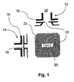
- the entire antenna is composed of an assembly of a waveguide 10 and a planar circuit antenna 30.
- Fig. 1 shows the waveguide 10.
- a waveguide flange 16 terminates a transceiver and a waveguide transition section 18 is designed to be compatible with the transceiver output.
- a "Doggy Bone" filter 20 is used inside the waveguide transition section 18, to reduce the level of spurious radiation at harmonic frequencies.
- Reference numeral 12 denotes a top view and 14 a side view of the waveguide 10.
- a waveguide length is used to keep a required distance between the filter 20 and the antenna plane so that the electromagnetic fields inside are not perturbed by the proximity of the two entities. Furthermore, the waveguide 10 is enlarged in its larger dimension to ensure a constant electromagnetic field on the antenna rear aperture (minimizing the E-field cosine variation inside the waveguide) and provide impedance matching.
- the planar antenna 30, shown in Fig. 2 is placed at the extremity of the waveguide length and the electromagnetic fields are coupled from the waveguide to the antenna by means of a rectangular aperture.
- This aperture is designed to provide enough energy to a central patch 50 of the substrate 31 of the planar antenna 30. Furthermore, it ensures a good match.
- After coupling the energy of the electromagnetic radiation to the central patch 50 it is also distributed to other patches 34, 36, 38, 40, 42, 44, 46, 48 by use of microstrip lines 58, 60, 62. The particularities of the coupling lines are explained below.
- the antenna structure is composed of three lines 33, 49, and 41 of three patches each.
- the left line 33 comprises patches 34, 36, 38, the right line 41 patches 42, 44, 46, and the central line 49 patches 40, 48, 50.
- Each line 33, 41, 49 forms an antenna element.
- the patches are electrically connected to each other by the mentioned microstrip lines 58, 60, and 62 respectively. Therefore, three antenna elements are formed on the planar antenna 30.
- the shape of the central patch 50 differs from the shapes of the other patches 34, 36, 38, 40, 42, 44, 46, and 48, due to its coupling function with the waveguide 10.
- the other patches 34, 36, 38, 40, 42, 44, 46, and 48 are patches which have a length optimized to make each patch resonate at the central frequency of the antenna.
- the width of the patches 34, 36, 38, 40, 42, 44, 46, and 48 is used to adjust the impedance and radiation power of the antenna. This technique is also applicable to larger size antenna, particularly antennas with larger dimensioned patches and/or more patches.
- the antenna is composed of three antenna elements or lines respectively of three patches each. Inside each line, the coupling is ensured by two (microstrip) lines 58, 60 connected on each side of the central patch 50 and feeding the edge patches 34, 36, 38, 40, 42, 44, 46, and 48.
- the length of each of these lines 58, 60 is designed so that the patches 34, 36, 38, 40, 42, 44, 46, and 48 are all radiating in phase along the line.
- the two lateral lines 58 and 60 are then linked to the central line 62 by horizontal coupling lines 61, 63, which have been designed to feed the lateral lines 58, 60 in phase and to save symmetry along the structure of the antenna 30.
- Some matching and relative power adjustment can be provided by the change of microstrip impedance resulting from the change in line width. This is useful to adjust the antenna horizontal radiation pattern and to optimize the return loss of the entire assembly.
- the power generated by the waveguide 10 on the central patch 50 is distributed to all the antenna elements 33, 41, 49 with the required proportion.
- PIN diodes 56 and 57 which are mounted on the horizontal coupling lines 63 and 61 respectively. These diodes 56 and 57 act as active switches with which the patches 34, 36, 38, and 42, 44, 46 can be connected with or disconnected from the central patch 50. This allows the control of the flow of microwave power to the lateral patches 34, 36, 38, and 42, 44, 46.
- the PIN-diodes 56 and 57 have the property to provide a low series resistance in "ON” state and a low capacitance in "OFF” state. Therefore, they are preferred elements in order to provide good switching performance without complicated matching circuitry around the PIN-diodes.
- the two lateral patch lines 33 and 41 are fed and the antenna behaves like a 3 x 3 patches antenna giving a narrow lobe in the horizontal plane. This configuration is used for narrow lobe applications.
- the antenna comprises a single line patch antenna with patches 40, 48, 50 and a wide radiation or reception pattern in the horizontal plane and a radiation or reception pattern similar to the pattern of a narrow lobe antenna in the vertical plane.
- the diodes 56 and 57 can be surface mount devices (SMD) having minimum package parasitic.
- SMD surface mount devices
- the diodes 56 and 57 can be mounted on the center of a matching pad where the microstrip width is larger. At this point, the level of impedance is rather low and the impedance of the diode in "OFF" state is sufficiently high to provide good isolation.
- Electromagnetic simulations have shown that a resonant patch antenna has a maximum voltage at the edges and a minimum on the center of the lateral side. This is precisely where a thin line is connected to provide the DC current to the diodes. Electromagnetic simulations have also shown that the rejection of Microwave power, using this strategy could reach up to 35 dB.
- Fig. 3 shows the DC-path of the antenna 30. DC-Current is applied by means of connection-pads 52 and 54, which are connected by thin lines to the patches 34 and 46 respectively.
- Fig. 4 indicates the absorbing material applied to the surface of the antenna. The shape of the absorbing material is designed to stay on the antenna substrate.
- Fig. 5 shows two possible lobes 70 and 72 generated by switching the configuration of the antenna.
- the lobes 70 and 72 relate to the horizontal distribution of the radiation patterns of the two configurations of the antenna. A mechanical change of the antenna is no longer required.
- a single antenna can simply provide different lobes by electronically switching.
- the radiation pattern 80 is almost the same independently of the antenna configuration, as shown in Fig. 6 . Therefore, the vertical radiation pattern 80 is nearly identical for both configurations of the planar antenna 30.
- Such an antenna has also the advantage to be readily compatible with existing low cost transceivers based on waveguide technology.
- the assembly of such devices is less critical and the implementation is more rugged than a full planar solution.
- a foam radome can be used to protect the diodes.
- Electronic switching of the antenna opens the way to a control of the antenna by a processor and, by that mean, an adjustment of the radiation pattern by remote control. Not only it is possible to switch between the two extreme configurations, but also, through the use of an algorithm, it is possible to generate equivalent detection lobes being in between the two extremes. A weighting of the Doppler signal received in each configuration will be used to get all the intermediate states required.
- Fig. 7 shows an circuitry for IF Processing connected to a microwave transceiver 106.
- the transceiver 106 comprises a waveguide mounted on a planar antenna 30.
- the processing obtains the Doppler signals of two Schottky diodes 100 and 102 provided in the microwave transceiver 106 for each of the two antenna configurations.
- a signal received by the antenna 30 is sampled in each configuration of the antenna 30 and a high speed switching is done between the two configurations of the antenna 30.
- Sample and hold circuits 114, 116, 118, and 120 are synchronized with the switching of the configurations of the antenna 30 in order to switch the output signals of the Sample and hold circuits 114, 116, 118, and 120 on the corresponding channels.
- the sampling clock can be provided either by the processor or by an auxiliary oscillator 108 whose frequency accuracy is not critical, provided it remains sufficiently high in order to provide good sampling.
- Pulse Width Modulation PWM
- PWM Pulse Width Modulation
- planar active antenna 30 used in an active antenna sensor delivers more information than a single antenna.
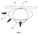
- the use of the extra information received from the planar active antenna 30 can lead to an effective pedestrian parallel traffic rejection algorithm used in door opener systems, as shown in Fig. 8 .
- Fig. 8 By observing simultaneously the amplitude of the Doppler signal coming from the two antenna configurations of an active antenna sensor 152 mounted on top of a door 150, it is possible to determine from which side a pedestrian is coming.
- the horizontal radiation patterns of the active antenna sensor 152 are carefully chosen one could then correlate the information generated by the same target in both antenna configurations in order to approximate the angle of the target trajectory compare to the axis of the sensor.
- the magnitude of the signals corresponding to the second configuration detection field 156 will be higher than the one corresponding to the first configuration detection field 154 (wide field).
- the magnitude of the signals corresponding to the wide detection field will be higher than the one corresponding to the narrow field.
Landscapes
- Engineering & Computer Science (AREA)
- Radar, Positioning & Navigation (AREA)
- Remote Sensing (AREA)
- Computer Networks & Wireless Communication (AREA)
- Physics & Mathematics (AREA)
- General Physics & Mathematics (AREA)
- Variable-Direction Aerials And Aerial Arrays (AREA)
- Waveguide Aerials (AREA)
- Radar Systems Or Details Thereof (AREA)
- Details Of Aerials (AREA)
Claims (23)
- Une antenne plane (30) comportant: une pluralité d'antennes (33, 41, 49) placées l'une relative à l'autre dans une orientation prédéterminée, chacune desdites antennes (33, 41, 49) comportant au moins un patch (34, 36, 38, 40, 42, 44, 46, 48, 50) électriquement connectés entre eux pour former une rangée verticale montée sur un support plan, chacune des antennes (33, 41, 49) étant sélectivement raccordable électriquement à une ou plusieurs des autres antennes (33, 41, 49) par l'intermédiaire d'une pluralité de commutateurs (56, 57) de sorte que la fermeture d'un des commutateurs (56, 57) entraîne la connexion électrique des deux antennes adjacentes, et la pluralité des antennes (33, 41, 49) définissant une rangée d'antennes horizontale, caractérisée en ce que la rangée d'antennes horizontale est constituée d'une antenne centrale (49) et d'au moins une antenne latérale (33, 41), l'antenne centrale (49) est connectée par l'intermédiaire des lignes horizontales (61, 63) aux commutateurs (56, 57) aux antennes d'au moins une antenne latérale (33, 41), les commutateurs (56, 57) sont commandés de sorte que dans l'état "ON", une ou plusieurs des antennes latérales (33, 41) sont connectées à l'antenne centrale (49) ce qui donne un lobe plus étroit dans le plan horizontal et dans l'état "OFF", une antenne latérale (33, 41) au moins est débranchée et seule l'antenne centrale (49) est active, créant un lobe large dans le plan horizontal.
- Une antenne plane selon la revendication 1, caractérisée en ce que les commutateurs (56, 57) sont situés sur le support d'antenne.
- Une antenne plane selon les revendications 1 et 2, caractérisée en ce que les patchs (34, 36, 38, 40, 42, 44, 46, 48, 50) comportent un patch central (50) qui remplit la fonction de couplage à des circuits micro-ondes, comme un guide d'ondes (10), une sonde coaxiale, par l'intermédiaire d'un trou, un couplage à fente ou toute autre type de couplage.
- Une antenne plane selon les revendications 1 à 3, caractérisée en ce que tous les autres patchs (34, 36, 38, 40, 42, 44, 46, 48) ont une longueur qui est optimisée pour faire résonner le patch respectif à une fréquence centrale et une largeur qui est ajustée à l'impédance et à la puissance de rayonnement de l'antenne.
- Une antenne plane selon une quelconque des revendications précédentes, caractérisée en ce qu'elle comprend une antenne latérale gauche, une antenne centrale et une antenne latérale droite (33, 41, 49) comprenant chacune trois patchs (34, 36, 38, 40, 42, 44, 46, 48, 50), dans laquelle les patchs de chaque antenne sont connectés électriquement par des lignes verticales (58, 60, 62) et les antennes gauche et droite (33, 41) respectivement et l'antenne centrale (49) sont électriquement connectables à l'aide d'interrupteurs (56, 57).
- Une antenne plane selon une des revendications précédentes, caractérisée en ce qu'elle comporte un guide d'ondes (10) pour le couplage à l'antenne plane.
- Une antenne plane selon la revendication 6, caractérisée en ce que le guide d'ondes (10) comporte une transition (18) vers l'antenne plane qui se termine par le raccord à bride du guide d'ondes (16).
- Une antenne plane selon la revendication 6 ou 7, caractérisée en ce que la transition (18) comporte un filtre "Doggy bone" (en forme d'haltère) (20) qui réduit le rayonnement parasite aux fréquences harmoniques.
- Une antenne plane selon la revendication 8, caractérisée en ce que la distance entre le filtre "doggy bone" (20) et le plan de l'antenne plane (30) est approximativement de la longueur d'un guide d'ondes lorsque le guide d'ondes (10) est monté sur la surface de l'antenne plane (30).
- Une antenne plane selon l'une quelconque des revendications 6 à 9, caractérisée en ce que le guide d'ondes (10) est agrandi dans le sens de la largeur afin d'assurer un champ électromagnétique constant sur son ouverture arrière et permettre l'adaptation d'impédance.
- Une antenne plane selon l'une quelconque des revendications 6 à 10, caractérisée en ce que le guide d'ondes (10) comporte une ouverture rectangulaire qui est conçue pour fournir assez d'énergie au patch central (50) et d'assurer une bonne concordance entre le guide d'ondes (10) et l'antenne plane (30).
- Une antenne plane selon l'une quelconque des revendications précédentes, caractérisée en ce que les commutateurs sont des diodes PIN.
- Une antenne plane selon la revendication 12, caractérisée en ce qu'un chemin est fourni pour qu'un courant continu polarise les diodes PIN et formé pour n'avoir aucune influence sur le schéma de rayonnement de l'antenne.
- Une antenne plane selon l'une quelconque des revendications précédentes, caractérisée en ce qu'au moins les pads de connexion (52, 54) pour l'application du courant continu aux commutateurs et/ou une partie des lignes de commande (66, 68) sont couverts d'une matière absorbant les micro-ondes.
- Une antenne plane selon une quelconque des revendications précédentes, caractérisée par un circuit pour la commande de l'antenne plane (30) en obtenant au moins un Doppler Signal d'au moins un dispositif de mesure (100, 102) fonctionnant avec au moins un lobe de l'antenne plane (30), traitant les Signaux Doppler selon un algorithme et effectuant une commutation à grande vitesse entre les configurations de l'antenne plane (30) selon l'algorithme.
- Une antenne plane selon la revendication 15, caractérisée en ce que les circuits comportent des circuits d'échantillonnage et des circuits de maintien (114, 116, 118, 120) pour le prélèvement des Signaux Doppler obtenus.
- Une antenne plane selon la revendication 16, caractérisée en ce que les circuits de prélèvement et de maintien (114, 116, 118, 120) sont synchronisés avec la commutation à grande vitesse.
- Une antenne plane selon l'une quelconque des revendications 15 à 17, caractérisée en ce que les circuits comportent un processeur de signal numérique pour traiter au moins un Signal Doppler.
- Une antenne plane selon la revendication 18, caractérisée en ce que le processeur du signal numérique traite deux signaux Doppler obtenus à partir de deux dispositifs de mesure (100, 102) correspondant à deux lobes différents de l'antenne plane et à partir des signaux Doppler calcule un lobe intermédiaire par pondération des signaux Doppler.
- Une antenne plane selon l'une quelconque des revendications 15 à 19, caractérisée en ce que les circuits comportent un oscillateur (108) qui produit un signal de fréquence de prélèvement (φ) avec une précision appropriée au prélèvement.
- Une antenne plane selon l'une quelconque des revendications 15 à 20, caractérisée en ce que les circuits sont formés pour effectuer le prélèvement par la modulation de largeur d'impulsion.
- Une antenne plane selon une quelconque des revendications précédentes, caractérisée en ce qu'elle est utilisée dans un capteur d'ouverture de porte (152).
- Dispositif qui utilise une antenne plane selon une quelconque des revendications précédentes, caractérisé en ce que le capteur d'ouverture de porte (152) effectue un algorithme parallèle de rejet de trafic qui traite l'information reçue de l'antenne plane de telle manière qu'au moins deux lobes différents (154, 156) de l'antenne plane sont analysés afin de calculer la direction d'un piéton se déplaçant ou s'approchant du domaine couvert par le capteur d'ouverture de porte (152) .
Priority Applications (12)
| Application Number | Priority Date | Filing Date | Title |
|---|---|---|---|
| DE60141366T DE60141366D1 (de) | 2001-10-19 | 2001-10-19 | Verfahren zur Detektierung von Bewegungen in der Nähe von automatischen Türen |
| EP07109302A EP1832895B1 (fr) | 2001-10-19 | 2001-10-19 | Procédé pour la détection des mouvements autour des portes automatiques |
| EP01125007A EP1304764B1 (fr) | 2001-10-19 | 2001-10-19 | Antenne plane |
| ES07109302T ES2341185T3 (es) | 2001-10-19 | 2001-10-19 | Metodo de deteccion del movimiento alrededor de puertas automaticas. |
| ES01125007T ES2300296T3 (es) | 2001-10-19 | 2001-10-19 | Antena plana. |
| DE60133007T DE60133007T2 (de) | 2001-10-19 | 2001-10-19 | Ebene Antenne |
| CNB021058040A CN1251356C (zh) | 2001-10-19 | 2002-04-10 | 平面天线 |
| US10/122,553 US6700542B2 (en) | 2001-10-19 | 2002-04-15 | Planar antenna |
| KR1020020027387A KR20030032807A (ko) | 2001-10-19 | 2002-05-17 | 플레이너 안테나 |
| JP2002301038A JP4021740B2 (ja) | 2001-10-19 | 2002-10-15 | 平面アンテナ |
| HK03107661.0A HK1057132B (en) | 2003-10-23 | Planar antenna | |
| US10/767,829 US7129892B2 (en) | 2001-10-19 | 2004-01-28 | Planar antenna |
Applications Claiming Priority (1)
| Application Number | Priority Date | Filing Date | Title |
|---|---|---|---|
| EP01125007A EP1304764B1 (fr) | 2001-10-19 | 2001-10-19 | Antenne plane |
Related Child Applications (1)
| Application Number | Title | Priority Date | Filing Date |
|---|---|---|---|
| EP07109302A Division EP1832895B1 (fr) | 2001-10-19 | 2001-10-19 | Procédé pour la détection des mouvements autour des portes automatiques |
Publications (2)
| Publication Number | Publication Date |
|---|---|
| EP1304764A1 EP1304764A1 (fr) | 2003-04-23 |
| EP1304764B1 true EP1304764B1 (fr) | 2008-02-27 |
Family
ID=8179024
Family Applications (2)
| Application Number | Title | Priority Date | Filing Date |
|---|---|---|---|
| EP01125007A Expired - Lifetime EP1304764B1 (fr) | 2001-10-19 | 2001-10-19 | Antenne plane |
| EP07109302A Expired - Lifetime EP1832895B1 (fr) | 2001-10-19 | 2001-10-19 | Procédé pour la détection des mouvements autour des portes automatiques |
Family Applications After (1)
| Application Number | Title | Priority Date | Filing Date |
|---|---|---|---|
| EP07109302A Expired - Lifetime EP1832895B1 (fr) | 2001-10-19 | 2001-10-19 | Procédé pour la détection des mouvements autour des portes automatiques |
Country Status (7)
| Country | Link |
|---|---|
| US (2) | US6700542B2 (fr) |
| EP (2) | EP1304764B1 (fr) |
| JP (1) | JP4021740B2 (fr) |
| KR (1) | KR20030032807A (fr) |
| CN (1) | CN1251356C (fr) |
| DE (2) | DE60141366D1 (fr) |
| ES (2) | ES2341185T3 (fr) |
Cited By (1)
| Publication number | Priority date | Publication date | Assignee | Title |
|---|---|---|---|---|
| EP1655434B1 (fr) | 2004-11-04 | 2015-04-22 | DORMA Deutschland GmbH | Ensemble de porte avec vanteaux déplaçables automatiquement et méthode pour opérer de tels ensembles de porte |
Families Citing this family (56)
| Publication number | Priority date | Publication date | Assignee | Title |
|---|---|---|---|---|
| CN100367564C (zh) * | 2001-12-04 | 2008-02-06 | 松下电器产业株式会社 | 天线以及具有该天线的装置 |
| US6788258B2 (en) * | 2002-04-09 | 2004-09-07 | Arc Wireless Solutions, Inc. | Partially shared antenna aperture |
| KR100562785B1 (ko) * | 2002-11-25 | 2006-03-27 | 충남대학교산학협력단 | 프린트형 능동 야기-우다 안테나 |
| DE10328590A1 (de) * | 2003-06-25 | 2005-01-20 | Siemens Ag | Funkfernbedienung zur Abgabe von Befehlen an ein fernbedienbares Gerät |
| JP4590595B2 (ja) * | 2003-09-09 | 2010-12-01 | 独立行政法人情報通信研究機構 | 広帯域複数周波共用アンテナ |
| US7163155B2 (en) * | 2003-11-05 | 2007-01-16 | Interdigital Technology Corporation | ASIC-embedded switchable antenna arrays |
| US7187334B2 (en) * | 2004-10-29 | 2007-03-06 | Motorola, Inc. | Patch array feed for an automotive radar antenna |
| ES2572772T3 (es) * | 2005-01-21 | 2016-06-02 | Bea S.A. | Sensor para utilizar en puertas automáticas |
| US7656364B2 (en) * | 2005-08-30 | 2010-02-02 | Telefonaktiebolaget L M Ericsson (Publ) | Systems and methods for a multi-mode reconfigurable sector antenna |
| US8380132B2 (en) * | 2005-09-14 | 2013-02-19 | Delphi Technologies, Inc. | Self-structuring antenna with addressable switch controller |
| GB0604032D0 (en) * | 2006-02-28 | 2006-04-12 | E2V Tech Uk Ltd | Vehicle intruder alarm |
| US20070293178A1 (en) * | 2006-05-23 | 2007-12-20 | Darin Milton | Antenna Control |
| US7761115B2 (en) * | 2006-05-30 | 2010-07-20 | Broadcom Corporation | Multiple mode RF transceiver and antenna structure |
| EP2074603B1 (fr) * | 2006-09-28 | 2012-05-02 | Bea S.A. | Capteur de détection de présence |
| KR100842525B1 (ko) * | 2006-11-14 | 2008-07-01 | 삼성전자주식회사 | 휴대 단말기의 내장형 안테나 장치 |
| KR100842271B1 (ko) * | 2006-12-05 | 2008-06-30 | 한국전자통신연구원 | Rfid 리더용 선형 편파 다이버시티 안테나 장치 및 그제어 방법 |
| KR100842087B1 (ko) * | 2006-12-28 | 2008-06-30 | 삼성전자주식회사 | 어레이 안테나 시스템 |
| EP2130312A4 (fr) * | 2007-04-05 | 2010-03-10 | Keyless Technologies Pty Ltd | Système de contrôle d'accès à un portail |
| US7508346B2 (en) * | 2007-04-16 | 2009-03-24 | Research In Motion Limited | Dual-polarized, microstrip patch antenna array, and associated methodology, for radio device |
| EP2040336B1 (fr) * | 2007-08-03 | 2015-09-09 | InnoSenT GmbH | Capteur de radar |
| WO2009052234A1 (fr) | 2007-10-19 | 2009-04-23 | Board Of Trustees Of Michigan State University | Antenne à plaque à fréquence variable |
| DE102008008149B4 (de) | 2008-02-08 | 2022-01-05 | Agtatec Ag | Verfahren sowie Vorrichtung zur Ansteuerung und/oder Überwachung eines verfahrbaren Flügels, insbesondere einer Tür, eines Fensters oder dergleichen |
| DE102008008142B4 (de) | 2008-02-08 | 2019-01-17 | Agtatec Ag | Verfahren sowie Vorrichtung zur Ansteuerung und/oder Überwachung eines verfahrbaren Flügels, insbesondere einer Tür, eines Fensters oder dergleichen |
| US8340197B2 (en) * | 2008-02-28 | 2012-12-25 | Invertix Corporation | System and method for modulating a signal at an antenna |
| US8261491B2 (en) * | 2008-04-02 | 2012-09-11 | Leon Yulkowski | Concealed electrical door operator |
| DE102008023030B4 (de) | 2008-05-09 | 2016-11-17 | Innosent Gmbh | Radarantennenanordnung |
| WO2009144002A1 (fr) | 2008-05-30 | 2009-12-03 | Bircher Reglomat Ag | Procédé de surveillance d’une zone de mouvement |
| KR101044000B1 (ko) | 2008-11-13 | 2011-06-24 | 엘아이지넥스원 주식회사 | 도플러 주파수 측정방법과 장치 및 이를 이용한 레이더 세트의 시험 시스템 |
| US8457251B2 (en) * | 2008-11-25 | 2013-06-04 | Invertix Corporation | System and method for spreading and de-spreading a signal at an antenna |
| US8391376B2 (en) * | 2008-11-25 | 2013-03-05 | Invertix Corporation | System and method for electronically steering an antenna |
| US8411794B2 (en) * | 2008-11-25 | 2013-04-02 | Invertix Corporation | System and method for arbitrary phase and amplitude modulation in an antenna |
| US8653982B2 (en) | 2009-07-21 | 2014-02-18 | Openings | Door monitoring system |
| EP2309657A1 (fr) * | 2009-10-08 | 2011-04-13 | Thomson Licensing | Procédé de contrôle de la topologie utilisant des antennes sectorisées dans des réseaux sans fil |
| US8750792B2 (en) | 2012-07-26 | 2014-06-10 | Remec Broadband Wireless, Llc | Transmitter for point-to-point radio system |
| CN105874648B (zh) * | 2014-06-30 | 2020-04-21 | 华为技术有限公司 | 具有径向波导的宽带灵活圆柱形天线阵列的装置和方法 |
| US9490535B2 (en) | 2014-06-30 | 2016-11-08 | Huawei Technologies Co., Ltd. | Apparatus and assembling method of a dual polarized agile cylindrical antenna array with reconfigurable radial waveguides |
| US9502765B2 (en) | 2014-06-30 | 2016-11-22 | Huawei Technologies Co., Ltd. | Apparatus and method of a dual polarized broadband agile cylindrical antenna array with reconfigurable radial waveguides |
| US10378262B2 (en) | 2014-10-23 | 2019-08-13 | Leon Yulkowski | Door operator and clutch |
| DE102014118036A1 (de) | 2014-12-05 | 2016-06-23 | Astyx Gmbh | Radarantenne und geeignetes Verfahren zum Beeinflussen der Abstrahlcharakteristik einer Radarantenne |
| CN104466433A (zh) * | 2014-12-08 | 2015-03-25 | 马瑞利汽车电子(广州)有限公司 | 一种车载射频接收天线装置 |
| DE202016100413U1 (de) | 2016-01-05 | 2017-04-07 | Hörmann KG Antriebstechnik | Annäherungstaster für eine automatische Tür oder ein automatisches Tor |
| US20170222330A1 (en) * | 2016-01-28 | 2017-08-03 | Royaltek Company Ltd. | Antenna device |
| EP3285334A1 (fr) * | 2016-08-15 | 2018-02-21 | Nokia Solutions and Networks Oy | Réseau d'antennes de formation de faisceau |
| US10221610B2 (en) | 2017-05-15 | 2019-03-05 | Otis Elevator Company | Depth sensor for automatic doors |
| US10386460B2 (en) | 2017-05-15 | 2019-08-20 | Otis Elevator Company | Self-calibrating sensor for elevator and automatic door systems |
| GB2569620B (en) * | 2017-12-21 | 2021-12-29 | Canon Kk | Optimization of the performances of an antenna array |
| KR101943769B1 (ko) * | 2017-12-28 | 2019-04-17 | 광운대학교 산학협력단 | 배열 안테나 시스템 및 이를 이용한 빠른 전파 도달각 측정 방법 |
| DE102018100285B3 (de) | 2018-01-08 | 2019-04-25 | Hörmann KG Antriebstechnik | Taster-Vorrichtung und System mit einer Taster-Vorrichtung |
| DE102018202299A1 (de) * | 2018-02-15 | 2019-08-22 | Robert Bosch Gmbh | Antennenanordnung für einen Radarsensor |
| US10446930B1 (en) * | 2018-06-25 | 2019-10-15 | Nxp B.V. | Antenna combination device |
| CN109638437A (zh) * | 2018-12-07 | 2019-04-16 | 长沙瑞感电子科技有限公司 | 一种mimo毫米波微带阵列天线 |
| CN110581369A (zh) * | 2019-08-26 | 2019-12-17 | 维沃移动通信有限公司 | 一种天线模组及移动终端 |
| CN112201934B (zh) * | 2020-09-23 | 2021-10-08 | 华中科技大学 | 一种双频天线及天线阵列 |
| US12088013B2 (en) | 2021-03-30 | 2024-09-10 | Skyworks Solutions, Inc. | Frequency range two antenna array with switches for joining antennas for frequency range one communications |
| JP7775093B2 (ja) | 2022-02-02 | 2025-11-25 | オプテックス株式会社 | 自動ドアシステムおよび開閉システム |
| CN116742340A (zh) * | 2023-07-27 | 2023-09-12 | 中国联合网络通信集团有限公司 | 一种天线 |
Family Cites Families (35)
| Publication number | Priority date | Publication date | Assignee | Title |
|---|---|---|---|---|
| JPS52132656A (en) * | 1976-04-28 | 1977-11-07 | Mitsubishi Electric Corp | Strip line type micro wave control circuit |
| JPS59189302U (ja) * | 1983-06-03 | 1984-12-15 | 株式会社東芝 | 導波管フイルタ回路 |
| JP2561648B2 (ja) * | 1985-01-25 | 1996-12-11 | 三菱電機株式会社 | アンテナ装置 |
| GB2211357A (en) * | 1987-09-23 | 1989-06-28 | Philips Electronic Associated | Integrated millimetre-wave transceiver |
| JP2568585B2 (ja) * | 1987-10-15 | 1997-01-08 | 松下電器産業株式会社 | 移動体検出装置 |
| GB9002636D0 (en) * | 1990-02-06 | 1990-04-04 | British Telecomm | Antenna |
| GB9026037D0 (en) * | 1990-11-30 | 1991-01-16 | Marconi Gec Ltd | Motion detector unit |
| JPH04220094A (ja) * | 1990-12-19 | 1992-08-11 | Sony Corp | バースト位相検出回路 |
| JPH04299277A (ja) * | 1991-03-28 | 1992-10-22 | Mitsubishi Electric Corp | マイクロ波送受器 |
| US5315303A (en) * | 1991-09-30 | 1994-05-24 | Trw Inc. | Compact, flexible and integrated millimeter wave radar sensor |
| JPH0581764U (ja) * | 1992-04-01 | 1993-11-05 | 三菱電機株式会社 | 車両検出装置 |
| ATE180575T1 (de) * | 1993-08-09 | 1999-06-15 | Siemens Ag | Dopplerradarmodul in mikrostreifenleitungstechnik |
| US5512911A (en) * | 1994-05-09 | 1996-04-30 | Disys Corporation | Microwave integrated tuned detector |
| US5656980A (en) * | 1994-09-27 | 1997-08-12 | Harris Corporation | Multiple output RF filter and waveguide |
| JP3308734B2 (ja) * | 1994-10-13 | 2002-07-29 | 本田技研工業株式会社 | レーダーモジュール |
| JP3302848B2 (ja) * | 1994-11-17 | 2002-07-15 | 本田技研工業株式会社 | 車載レーダー装置 |
| JP3511329B2 (ja) * | 1995-06-09 | 2004-03-29 | 本田技研工業株式会社 | 車載用レーダ装置 |
| DE19535962C1 (de) * | 1995-09-27 | 1997-02-13 | Siemens Ag | Dopplerradarmodul |
| US6061025A (en) * | 1995-12-07 | 2000-05-09 | Atlantic Aerospace Electronics Corporation | Tunable microstrip patch antenna and control system therefor |
| DE19547289C2 (de) * | 1995-12-18 | 1998-02-12 | Siemens Ag | Frequenzmischer für ein Dopplerradarmodul |
| JPH09172323A (ja) * | 1995-12-20 | 1997-06-30 | Fujitsu General Ltd | 平面アンテナ |
| JP3602258B2 (ja) * | 1996-05-02 | 2004-12-15 | 本田技研工業株式会社 | マルチビーム・レーダアンテナ |
| US5933109A (en) * | 1996-05-02 | 1999-08-03 | Honda Giken Kabushiki Kaisha | Multibeam radar system |
| JPH1093322A (ja) * | 1996-09-18 | 1998-04-10 | Honda Motor Co Ltd | アンテナ装置 |
| US6064862A (en) * | 1997-07-18 | 2000-05-16 | Innova Corporation | Method and apparatus for external band selection of a digital microwave radio |
| JP3426934B2 (ja) * | 1997-10-09 | 2003-07-14 | 日本電信電話株式会社 | アンテナ装置 |
| US5966090A (en) * | 1998-03-16 | 1999-10-12 | Mcewan; Thomas E. | Differential pulse radar motion sensor |
| US6175723B1 (en) | 1998-08-12 | 2001-01-16 | Board Of Trustees Operating Michigan State University | Self-structuring antenna system with a switchable antenna array and an optimizing controller |
| US6020853A (en) * | 1998-10-28 | 2000-02-01 | Raytheon Company | Microstrip phase shifting reflect array antenna |
| US6377217B1 (en) * | 1999-09-14 | 2002-04-23 | Paratek Microwave, Inc. | Serially-fed phased array antennas with dielectric phase shifters |
| US6198438B1 (en) * | 1999-10-04 | 2001-03-06 | The United States Of America As Represented By The Secretary Of The Air Force | Reconfigurable microstrip antenna array geometry which utilizes micro-electro-mechanical system (MEMS) switches |
| JP4216979B2 (ja) * | 1999-12-24 | 2009-01-28 | 京セラ株式会社 | アンテナ給電線路およびそれを用いたアンテナモジュール |
| JP2001283347A (ja) * | 2000-03-28 | 2001-10-12 | Toto Ltd | 浴室人体検知装置 |
| AU6000001A (en) * | 2000-05-31 | 2001-12-11 | Reglomat Ag | Unit for controlling the position of a displaceable component |
| US6501427B1 (en) * | 2001-07-31 | 2002-12-31 | E-Tenna Corporation | Tunable patch antenna |
-
2001
- 2001-10-19 EP EP01125007A patent/EP1304764B1/fr not_active Expired - Lifetime
- 2001-10-19 ES ES07109302T patent/ES2341185T3/es not_active Expired - Lifetime
- 2001-10-19 ES ES01125007T patent/ES2300296T3/es not_active Expired - Lifetime
- 2001-10-19 DE DE60141366T patent/DE60141366D1/de not_active Expired - Lifetime
- 2001-10-19 DE DE60133007T patent/DE60133007T2/de not_active Expired - Lifetime
- 2001-10-19 EP EP07109302A patent/EP1832895B1/fr not_active Expired - Lifetime
-
2002
- 2002-04-10 CN CNB021058040A patent/CN1251356C/zh not_active Expired - Lifetime
- 2002-04-15 US US10/122,553 patent/US6700542B2/en not_active Expired - Lifetime
- 2002-05-17 KR KR1020020027387A patent/KR20030032807A/ko not_active Ceased
- 2002-10-15 JP JP2002301038A patent/JP4021740B2/ja not_active Expired - Fee Related
-
2004
- 2004-01-28 US US10/767,829 patent/US7129892B2/en not_active Expired - Lifetime
Non-Patent Citations (1)
| Title |
|---|
| None * |
Cited By (1)
| Publication number | Priority date | Publication date | Assignee | Title |
|---|---|---|---|---|
| EP1655434B1 (fr) | 2004-11-04 | 2015-04-22 | DORMA Deutschland GmbH | Ensemble de porte avec vanteaux déplaçables automatiquement et méthode pour opérer de tels ensembles de porte |
Also Published As
| Publication number | Publication date |
|---|---|
| CN1412890A (zh) | 2003-04-23 |
| JP4021740B2 (ja) | 2007-12-12 |
| DE60141366D1 (de) | 2010-04-01 |
| US20030076271A1 (en) | 2003-04-24 |
| EP1832895A2 (fr) | 2007-09-12 |
| EP1832895A3 (fr) | 2008-07-23 |
| ES2341185T3 (es) | 2010-06-16 |
| US20040185793A1 (en) | 2004-09-23 |
| JP2003198247A (ja) | 2003-07-11 |
| DE60133007T2 (de) | 2009-03-19 |
| EP1832895B1 (fr) | 2010-02-17 |
| KR20030032807A (ko) | 2003-04-26 |
| HK1057132A1 (en) | 2004-03-12 |
| DE60133007D1 (de) | 2008-04-10 |
| ES2300296T3 (es) | 2008-06-16 |
| US7129892B2 (en) | 2006-10-31 |
| CN1251356C (zh) | 2006-04-12 |
| EP1304764A1 (fr) | 2003-04-23 |
| US6700542B2 (en) | 2004-03-02 |
Similar Documents
| Publication | Publication Date | Title |
|---|---|---|
| EP1304764B1 (fr) | Antenne plane | |
| EP0642190B1 (fr) | Structure de rayonnement incorporé pour un capteur radar à ondes millimétriques | |
| US6717544B2 (en) | Radar sensor | |
| EP1438702B1 (fr) | Analyseur de trafic de vehicules | |
| EP2348329A1 (fr) | Détecteur d'ondes radio | |
| CN111755832B (zh) | 集成背腔缝隙阵列天线系统 | |
| US20100045536A1 (en) | Antenna apparatus | |
| US20200313287A1 (en) | Inverted microstrip travelling wave patch array antenna system | |
| JP4304642B1 (ja) | 電波センサ | |
| HK1057132B (en) | Planar antenna | |
| US6211833B1 (en) | Parking aid | |
| US20090040111A1 (en) | Antenna System for a Radar Sensor | |
| JP5671787B2 (ja) | 電波センサ | |
| JP5212903B2 (ja) | 電波センサ | |
| JP2010151611A (ja) | 電波センサ | |
| JP5515452B2 (ja) | 検波装置 | |
| JP2010096621A (ja) | 電波センサ | |
| JP5527709B2 (ja) | 電波センサ | |
| JP2010060356A (ja) | 電波センサ | |
| JP2010098507A (ja) | マイクロストリップアンテナおよび同マイクロストリップアンテナを備えた電波センサ | |
| JP2007104026A (ja) | マイクロストリップアンテナ及び高周波センサ |
Legal Events
| Date | Code | Title | Description |
|---|---|---|---|
| PUAI | Public reference made under article 153(3) epc to a published international application that has entered the european phase |
Free format text: ORIGINAL CODE: 0009012 |
|
| AK | Designated contracting states |
Designated state(s): AT BE CH CY DE DK ES FI FR GB GR IE IT LI LU MC NL PT SE TR |
|
| AX | Request for extension of the european patent |
Extension state: AL LT LV MK RO SI |
|
| 17P | Request for examination filed |
Effective date: 20030620 |
|
| RAP1 | Party data changed (applicant data changed or rights of an application transferred) |
Owner name: BEA S.A. |
|
| AKX | Designation fees paid |
Designated state(s): CH DE ES FR GB LI SE |
|
| 17Q | First examination report despatched |
Effective date: 20050202 |
|
| 17Q | First examination report despatched |
Effective date: 20050202 |
|
| GRAP | Despatch of communication of intention to grant a patent |
Free format text: ORIGINAL CODE: EPIDOSNIGR1 |
|
| GRAS | Grant fee paid |
Free format text: ORIGINAL CODE: EPIDOSNIGR3 |
|
| GRAA | (expected) grant |
Free format text: ORIGINAL CODE: 0009210 |
|
| AK | Designated contracting states |
Kind code of ref document: B1 Designated state(s): CH DE ES FR GB LI SE |
|
| REG | Reference to a national code |
Ref country code: GB Ref legal event code: FG4D |
|
| REG | Reference to a national code |
Ref country code: CH Ref legal event code: EP |
|
| REF | Corresponds to: |
Ref document number: 60133007 Country of ref document: DE Date of ref document: 20080410 Kind code of ref document: P |
|
| REG | Reference to a national code |
Ref country code: SE Ref legal event code: TRGR |
|
| REG | Reference to a national code |
Ref country code: CH Ref legal event code: NV Representative=s name: AMMANN PATENTANWAELTE AG BERN |
|
| REG | Reference to a national code |
Ref country code: ES Ref legal event code: FG2A Ref document number: 2300296 Country of ref document: ES Kind code of ref document: T3 |
|
| REG | Reference to a national code |
Ref country code: HK Ref legal event code: GR Ref document number: 1057132 Country of ref document: HK |
|
| ET | Fr: translation filed | ||
| PLBE | No opposition filed within time limit |
Free format text: ORIGINAL CODE: 0009261 |
|
| STAA | Information on the status of an ep patent application or granted ep patent |
Free format text: STATUS: NO OPPOSITION FILED WITHIN TIME LIMIT |
|
| 26N | No opposition filed |
Effective date: 20081128 |
|
| REG | Reference to a national code |
Ref country code: DE Ref legal event code: R082 Ref document number: 60133007 Country of ref document: DE Representative=s name: PUSCHMANN BORCHERT BARDEHLE PATENTANWAELTE PAR, DE |
|
| REG | Reference to a national code |
Ref country code: FR Ref legal event code: PLFP Year of fee payment: 15 |
|
| REG | Reference to a national code |
Ref country code: FR Ref legal event code: PLFP Year of fee payment: 16 |
|
| REG | Reference to a national code |
Ref country code: FR Ref legal event code: PLFP Year of fee payment: 17 |
|
| REG | Reference to a national code |
Ref country code: FR Ref legal event code: PLFP Year of fee payment: 18 |
|
| PGFP | Annual fee paid to national office [announced via postgrant information from national office to epo] |
Ref country code: DE Payment date: 20191031 Year of fee payment: 19 Ref country code: SE Payment date: 20191023 Year of fee payment: 19 |
|
| PGFP | Annual fee paid to national office [announced via postgrant information from national office to epo] |
Ref country code: ES Payment date: 20191120 Year of fee payment: 19 Ref country code: FR Payment date: 20191022 Year of fee payment: 19 |
|
| PGFP | Annual fee paid to national office [announced via postgrant information from national office to epo] |
Ref country code: CH Payment date: 20191023 Year of fee payment: 19 |
|
| PGFP | Annual fee paid to national office [announced via postgrant information from national office to epo] |
Ref country code: GB Payment date: 20191022 Year of fee payment: 19 |
|
| REG | Reference to a national code |
Ref country code: DE Ref legal event code: R119 Ref document number: 60133007 Country of ref document: DE |
|
| REG | Reference to a national code |
Ref country code: CH Ref legal event code: PL |
|
| REG | Reference to a national code |
Ref country code: SE Ref legal event code: EUG |
|
| GBPC | Gb: european patent ceased through non-payment of renewal fee |
Effective date: 20201019 |
|
| PG25 | Lapsed in a contracting state [announced via postgrant information from national office to epo] |
Ref country code: DE Free format text: LAPSE BECAUSE OF NON-PAYMENT OF DUE FEES Effective date: 20210501 Ref country code: FR Free format text: LAPSE BECAUSE OF NON-PAYMENT OF DUE FEES Effective date: 20201031 |
|
| PG25 | Lapsed in a contracting state [announced via postgrant information from national office to epo] |
Ref country code: SE Free format text: LAPSE BECAUSE OF NON-PAYMENT OF DUE FEES Effective date: 20201020 Ref country code: GB Free format text: LAPSE BECAUSE OF NON-PAYMENT OF DUE FEES Effective date: 20201019 Ref country code: LI Free format text: LAPSE BECAUSE OF NON-PAYMENT OF DUE FEES Effective date: 20201031 Ref country code: CH Free format text: LAPSE BECAUSE OF NON-PAYMENT OF DUE FEES Effective date: 20201031 |
|
| REG | Reference to a national code |
Ref country code: ES Ref legal event code: FD2A Effective date: 20220127 |
|
| PG25 | Lapsed in a contracting state [announced via postgrant information from national office to epo] |
Ref country code: ES Free format text: LAPSE BECAUSE OF NON-PAYMENT OF DUE FEES Effective date: 20201020 |