EP1308788A2 - Vorrichtung zum Ausrichten von Masken in der Fotolithographie - Google Patents
Vorrichtung zum Ausrichten von Masken in der Fotolithographie Download PDFInfo
- Publication number
- EP1308788A2 EP1308788A2 EP02023773A EP02023773A EP1308788A2 EP 1308788 A2 EP1308788 A2 EP 1308788A2 EP 02023773 A EP02023773 A EP 02023773A EP 02023773 A EP02023773 A EP 02023773A EP 1308788 A2 EP1308788 A2 EP 1308788A2
- Authority
- EP
- European Patent Office
- Prior art keywords
- mask
- masks
- adapter
- holder
- mask holder
- Prior art date
- Legal status (The legal status is an assumption and is not a legal conclusion. Google has not performed a legal analysis and makes no representation as to the accuracy of the status listed.)
- Withdrawn
Links
Images


Classifications
-
- G—PHYSICS
- G03—PHOTOGRAPHY; CINEMATOGRAPHY; ANALOGOUS TECHNIQUES USING WAVES OTHER THAN OPTICAL WAVES; ELECTROGRAPHY; HOLOGRAPHY
- G03F—PHOTOMECHANICAL PRODUCTION OF TEXTURED OR PATTERNED SURFACES, e.g. FOR PRINTING, FOR PROCESSING OF SEMICONDUCTOR DEVICES; MATERIALS THEREFOR; ORIGINALS THEREFOR; APPARATUS SPECIALLY ADAPTED THEREFOR
- G03F7/00—Photomechanical, e.g. photolithographic, production of textured or patterned surfaces, e.g. printing surfaces; Materials therefor, e.g. comprising photoresists; Apparatus specially adapted therefor
- G03F7/70—Microphotolithographic exposure; Apparatus therefor
- G03F7/70691—Handling of masks or workpieces
- G03F7/707—Chucks, e.g. chucking or un-chucking operations or structural details
-
- G—PHYSICS
- G03—PHOTOGRAPHY; CINEMATOGRAPHY; ANALOGOUS TECHNIQUES USING WAVES OTHER THAN OPTICAL WAVES; ELECTROGRAPHY; HOLOGRAPHY
- G03F—PHOTOMECHANICAL PRODUCTION OF TEXTURED OR PATTERNED SURFACES, e.g. FOR PRINTING, FOR PROCESSING OF SEMICONDUCTOR DEVICES; MATERIALS THEREFOR; ORIGINALS THEREFOR; APPARATUS SPECIALLY ADAPTED THEREFOR
- G03F7/00—Photomechanical, e.g. photolithographic, production of textured or patterned surfaces, e.g. printing surfaces; Materials therefor, e.g. comprising photoresists; Apparatus specially adapted therefor
- G03F7/70—Microphotolithographic exposure; Apparatus therefor
- G03F7/70691—Handling of masks or workpieces
- G03F7/70733—Handling masks and workpieces, e.g. exchange of workpiece or mask, transport of workpiece or mask
-
- G—PHYSICS
- G03—PHOTOGRAPHY; CINEMATOGRAPHY; ANALOGOUS TECHNIQUES USING WAVES OTHER THAN OPTICAL WAVES; ELECTROGRAPHY; HOLOGRAPHY
- G03F—PHOTOMECHANICAL PRODUCTION OF TEXTURED OR PATTERNED SURFACES, e.g. FOR PRINTING, FOR PROCESSING OF SEMICONDUCTOR DEVICES; MATERIALS THEREFOR; ORIGINALS THEREFOR; APPARATUS SPECIALLY ADAPTED THEREFOR
- G03F7/00—Photomechanical, e.g. photolithographic, production of textured or patterned surfaces, e.g. printing surfaces; Materials therefor, e.g. comprising photoresists; Apparatus specially adapted therefor
- G03F7/70—Microphotolithographic exposure; Apparatus therefor
- G03F7/70691—Handling of masks or workpieces
- G03F7/70733—Handling masks and workpieces, e.g. exchange of workpiece or mask, transport of workpiece or mask
- G03F7/70741—Handling masks outside exposure position, e.g. reticle libraries
Definitions
- the invention relates to a device for aligning masks in photolithography.
- the device according to the invention is suitable for a quick transition to different mask sizes with an automatic feed of Masks.
- the invention has for its object a cost-effective device for Alignment masks in photolithography to provide one easy and quick transition from one mask size to at least one others guaranteed.
- the invention is based on the following basic ideas.
- a first mask holder provided for a specific mask size at least one interchangeable adapter, which is preferably concentric in the Light passage opening of the first mask holder is arranged. Without adapter a larger mask can be held and by inserting the adapter a smaller mask size can be used.
- the second mask is arranged in a surface whose dimensions correspond to the area of the first mask. In this way can have the same frame and guidance for the second mask as for the first mask to be used.
- the invention can advantageously be used in the case of automatic mask feeding with the same mask magazines after a simple adaptation of an existing one Device for aligning masks are used. through the invention allows the transition of one mask size to at least one other simple, time-saving and inexpensive.
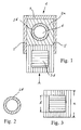
- FIG. 1 schematically shows an embodiment of a device according to the invention 1 for aligning masks in photolithography.
- a mask holder 2a is arranged in a frame 4.
- an adapter 2b is interchangeably arranged, which also makes it possible use a smaller mask than the one suitable for the mask holder 2a.
- FIG. 4 in which the mask holder 2a without an adapter is used and is intended for a large mask 3a.
- Fig. 1 is for the Adapter 2b provided a correspondingly smaller mask 3b.
- the mask 3b is in arranged on a surface that has the same side dimensions (square with the side length a) how the mask 3a has.
- the same frame 4 and the same guide rails 5 can be at least one additional mask 3b can be used.
- the device can be operated in the same way 1 also adapt to two or more additional masks by preferably Further adapters are arranged concentrically in the mask holder 2a. This means, these further masks would be like the second mask 3b in a square Surface arranged with the side length a and thus in the guide rails 5th be insertable.
- the mask 3b preferably has a side length b of 229 mm (9 inches) and enables the use of a smaller wafer in the device 1, the mask holder 2a preferably for a mask with side length a of 356 mm (14 Inch) is provided.
- FIG. 4 The use of the device 1 for the 14 inch mask is shown in FIG. 4, where the adapter 2b is removed so that the mask 3a can be used.
- the device 1 is for the automatic supply of masks from and suitable for the same magazine. Since the different masks are each in one Areas arranged with the same side lengths are in the same magazine stackable and are fed to the device 1 in the same way.
- the Masks are in the direction of arrow A in Figs. 1 and 4 over the corresponding one Mask holder 2a or the adapter 2b pushed into the guide rails 5 and with a wafer arranged under the device 1 (not shown) aligned. Having the appropriate masks in the same way removed, new masks can either be the same size or after inserting appropriate adapters with a smaller size.
- FIG. 5 shows a perspective view of a real image of the schematic Representation according to FIGS. 1 to 3. It can be seen in FIG. 5a that the mask holder 2a in the light passage opening 6 has recesses 7 into the corresponding one Projections 8 of the adapter 2b fit around the adapter 2b in the mask holder 2a align.
- 5b shows a second mask 3b with the side length b in an area with the side length a, which corresponds to the area of the 14 inch mask 3a.
- the mask 3b can be pinned at points 9 in the square area can be held interchangeably with the side length a.
- 5c shows the mask 3b on the adapter 2b, the structures of the adapter through the mask 3b seem to be.
- the invention is for quick replacement of 14 inch masks against 9 inch masks in an automated manufacturing process intended.
Landscapes
- Physics & Mathematics (AREA)
- General Physics & Mathematics (AREA)
- Engineering & Computer Science (AREA)
- Library & Information Science (AREA)
- Container, Conveyance, Adherence, Positioning, Of Wafer (AREA)
- Exposure And Positioning Against Photoresist Photosensitive Materials (AREA)
- Preparing Plates And Mask In Photomechanical Process (AREA)
Abstract
Description
- Fig. 1
- eine schematische Darstellung einer erfindungsgemäßen Ausführungsform,
- Fig. 2
- einen Adapter für die erfindungsgemäße Ausführungsform gemäß Fig. 1,
- Fig. 3
- eine Maske für die erfindungsgemäße Ausführungsform gemäß Fig. 1,
- Fig. 4
- die erfindungsgemäße Ausführungsform gemäß Fig. 1 ohne Adapter, und
- Fig. 5
- ein Realbild in perspektivischer Ansicht der schematischen Darstellungen gemäß Fig. 1 bis 3.
Claims (6)
- Vorrichtung zum Ausrichten von Masken in der Fotolithographie, wobei in einem ersten Maskenhalter (2a) mindestens ein Adapter (2b) für eine zweite Maske (3b) anordenbar ist, um mit dem ersten Maskenhalter (2a) mindestens einen zweiten Maskenhalter auszubilden, so dass entweder an den ersten Maskenhalter (2a) oder an den Adapter (2b) angepasste erste oder zweite Masken (3a bzw. 3b) in der Vorrichtung verwendbar sind.
- Vorrichtung nach Anspruch 1, wobei der Adapter (2b) konzentrisch in einer Lichtdurchlassöffnung (6) des ersten Maskenhalters (2a) angeordnet ist.
- Vorrichtung nach Anspruch 1 oder 2, wobei die erste Maske (3a) eine quadratische Fläche mit einer Seitenlänge von 356 mm und die zweite Maske (3b) eine quadratische Fläche mit einer Seitenlänge von 229 mm aufweist.
- Vorrichtung nach einem der Ansprüche 1 bis 3 mit einem Rahmen (4), an dem der erste Maskenhalter (2a) angeordnet ist, wobei der Rahmen (4) eine Führung (5) aufweist, in der entweder die erste Maske (3a) oder die zweite Maske (3b) zum Ausrichten mit einem Substrat über dem ersten Maskenhalter (2a) oder dem Adapter (2b) bewegbar ist, und wobei die zweite Maske (3b) in einer Fläche mit den Seitenmaßen der ersten Maske (3a) angeordnet ist.
- Vorrichtung nach einem der Ansprüche 1 bis 4, wobei die erste und die zweite Maske (3a bzw. 3b) aus einem gleichen Maskenmagazin zuführbar sind.
- Vorrichtung nach einem der Ansprüche 1 bis 5, wobei in dem ersten Maskenhalter (2a) zwei Adapter für zwei Masken anordenbar sind, so dass die Vorrichtung (1) für drei Masken einsetzbar ist.
Applications Claiming Priority (2)
| Application Number | Priority Date | Filing Date | Title |
|---|---|---|---|
| DE10153851 | 2001-11-02 | ||
| DE10153851A DE10153851B4 (de) | 2001-11-02 | 2001-11-02 | Vorrichtung zum Ausrichten von Masken in der Fotolithographie |
Publications (2)
| Publication Number | Publication Date |
|---|---|
| EP1308788A2 true EP1308788A2 (de) | 2003-05-07 |
| EP1308788A3 EP1308788A3 (de) | 2004-04-28 |
Family
ID=7704400
Family Applications (1)
| Application Number | Title | Priority Date | Filing Date |
|---|---|---|---|
| EP02023773A Withdrawn EP1308788A3 (de) | 2001-11-02 | 2002-10-25 | Vorrichtung zum Ausrichten von Masken in der Fotolithographie |
Country Status (4)
| Country | Link |
|---|---|
| US (1) | US6891602B2 (de) |
| EP (1) | EP1308788A3 (de) |
| DE (1) | DE10153851B4 (de) |
| TW (1) | TWI303018B (de) |
Families Citing this family (7)
| Publication number | Priority date | Publication date | Assignee | Title |
|---|---|---|---|---|
| JP2003158173A (ja) * | 2001-11-20 | 2003-05-30 | Oki Electric Ind Co Ltd | ウェハホルダ |
| US20040130695A1 (en) * | 2003-01-08 | 2004-07-08 | Vyacheslav Ananyev | Kit for converting a photolithography machine for treating semiconductor wafers of certain diameter to a machine for treating semiconductor wafers of larger diameter |
| DE10303902B4 (de) * | 2003-01-31 | 2004-12-09 | Süss Microtec Lithography Gmbh | Verfahren und Vorrichtung zum Ausrichten eines Justier-Mikroskops mittels verspiegelter Justiermaske |
| US20070190430A1 (en) * | 2006-02-10 | 2007-08-16 | Heng-Chung Wu | Photo-mask stage |
| CN102566255A (zh) * | 2010-12-27 | 2012-07-11 | 北大方正集团有限公司 | 一种用于曝光机对准的光罩及光罩对准标记制作方法 |
| JP7291684B2 (ja) * | 2018-10-29 | 2023-06-21 | 家登精密工業股▲ふん▼有限公司 | レチクル保持システム |
| JP7517155B2 (ja) * | 2019-02-06 | 2024-07-17 | 株式会社ニコン | マスクアダプタ、マスクアダプタ取付工具、露光装置、およびデバイス製造方法 |
Family Cites Families (9)
| Publication number | Priority date | Publication date | Assignee | Title |
|---|---|---|---|---|
| US4443098A (en) * | 1982-12-21 | 1984-04-17 | General Signal Corporation | Pellicle mounting fixture |
| JPH0648507Y2 (ja) * | 1986-08-30 | 1994-12-12 | ノーリツ鋼機株式会社 | 写真焼付におけるペーパーマスク装置 |
| JPH01257151A (ja) * | 1988-04-07 | 1989-10-13 | Shin Etsu Chem Co Ltd | 光通信ガラスファイバ用被覆剤及び光通信ガラスファイバ |
| JPH06325996A (ja) * | 1993-05-12 | 1994-11-25 | Hitachi Ltd | レティクルフレーム |
| JPH1055944A (ja) * | 1996-08-08 | 1998-02-24 | Toshiba Corp | パターン転写装置 |
| IL119213A (en) * | 1996-09-06 | 2000-08-31 | Orbot Instr Ltd | Universal chuck for holding plates of various sizes |
| JPH1197327A (ja) * | 1997-09-17 | 1999-04-09 | Rohm Co Ltd | 露光装置のマスク取付機構 |
| DE19810055A1 (de) | 1998-03-09 | 1999-09-23 | Suess Kg Karl | Verfahren zur Nahfeldbelichtung mit im wesentlichen parallelem Licht |
| JP2001257151A (ja) | 2000-03-13 | 2001-09-21 | Nikon Corp | 露光装置及びそれを用いたデバイス製造方法 |
-
2001
- 2001-11-02 DE DE10153851A patent/DE10153851B4/de not_active Expired - Lifetime
-
2002
- 2002-10-25 EP EP02023773A patent/EP1308788A3/de not_active Withdrawn
- 2002-10-30 TW TW091132193A patent/TWI303018B/zh not_active IP Right Cessation
- 2002-10-31 US US10/284,888 patent/US6891602B2/en not_active Expired - Lifetime
Also Published As
| Publication number | Publication date |
|---|---|
| US20030086069A1 (en) | 2003-05-08 |
| EP1308788A3 (de) | 2004-04-28 |
| DE10153851B4 (de) | 2006-11-16 |
| DE10153851A1 (de) | 2003-05-22 |
| TWI303018B (en) | 2008-11-11 |
| TW200300223A (en) | 2003-05-16 |
| US6891602B2 (en) | 2005-05-10 |
Similar Documents
| Publication | Publication Date | Title |
|---|---|---|
| EP0157288B1 (de) | Einrichtung für die Handbestückung von Leiterplatten | |
| DE112018003050B4 (de) | Drahtfixierungsvorrichtung und lötverfahren | |
| DE10153851B4 (de) | Vorrichtung zum Ausrichten von Masken in der Fotolithographie | |
| DE10010865B4 (de) | Verfahren zum Schneiden eines laminierten Werkstücks | |
| EP3482935B1 (de) | Siebeinheit für eine druckvorrichtung | |
| DE3142794C2 (de) | Siebdruckverfahren und -vorrichtung | |
| EP0391085A2 (de) | Vorrichtung zum Befestigen und Wechseln von Werkzeugen | |
| DE4033125A1 (de) | Vorrichtung zum transport und zum separieren von torsionsfedern | |
| EP0626125B1 (de) | Gerät und verfahren zum bedrucken eines schaltungsträgers | |
| WO2001057541A1 (de) | Adapter zum prüfen von leiterplatten und prüfnadel für einen solchen adapter | |
| DE102012209353A1 (de) | Prüfvorrichtung zum Testen einer Flachbaugruppe | |
| DE29904042U1 (de) | Stufenbohrer | |
| DE102017107446A1 (de) | Greifvorrichtung, insbesondere zum Greifen und Handhaben von Leiterplatten | |
| DE2242397A1 (de) | Steuereinrichtung fuer schuhbearbeitungsmaschinen | |
| DE3625038A1 (de) | Vorrichtung zur halterung von flachbaugruppen | |
| DE3447849C2 (de) | Vorrichtung zum doppelseitigen Belichten von Leiterplatten | |
| DE10340794B4 (de) | Folgewerkzeug zum Herstellen eines komplex geformten und mit Öffnungen in verschiedenen Ebenen versehenen Bauteils | |
| DE69014994T2 (de) | Gerät zur Halterung von Platten. | |
| DE112019004299T5 (de) | Lichtleiterausrichtungsschablone, Lichtleiterfusionsspleisser, der mit Lichtleiterausrichtungsschablone ausgerüstet ist, und Verfahren zum Ausrichten von Lichtleiter | |
| DE202019000787U1 (de) | Fixierwerkzeug zum Verlöten von Steckverbindern mit Lötkontakten | |
| DE10203048C2 (de) | Verfahren und Vorrichtung zum Zuordnen von Registerabweichungen bei einer Druckmaschine | |
| DE102018105388A1 (de) | Lötdüse und Lötanlage | |
| DE3237102C1 (de) | Saugspannplatte | |
| DE202023101782U1 (de) | Fixiersystem | |
| DE102024119296A1 (de) | Crimpzange mit Aufbewahrungs- und Austauschfunktion |
Legal Events
| Date | Code | Title | Description |
|---|---|---|---|
| PUAI | Public reference made under article 153(3) epc to a published international application that has entered the european phase |
Free format text: ORIGINAL CODE: 0009012 |
|
| AK | Designated contracting states |
Designated state(s): AT BE BG CH CY CZ DE DK EE ES FI FR GB GR IE IT LI LU MC NL PT SE SK TR |
|
| AX | Request for extension of the european patent |
Extension state: AL LT LV MK RO SI |
|
| PUAL | Search report despatched |
Free format text: ORIGINAL CODE: 0009013 |
|
| AK | Designated contracting states |
Kind code of ref document: A3 Designated state(s): AT BE BG CH CY CZ DE DK EE ES FI FR GB GR IE IT LI LU MC NL PT SE SK TR |
|
| AX | Request for extension of the european patent |
Extension state: AL LT LV MK RO SI |
|
| RIC1 | Information provided on ipc code assigned before grant |
Ipc: 7G 03F 7/20 B Ipc: 7G 03F 9/00 A |
|
| AKX | Designation fees paid | ||
| REG | Reference to a national code |
Ref country code: DE Ref legal event code: 8566 |
|
| STAA | Information on the status of an ep patent application or granted ep patent |
Free format text: STATUS: THE APPLICATION IS DEEMED TO BE WITHDRAWN |
|
| 18D | Application deemed to be withdrawn |
Effective date: 20041102 |