EP1342202B1 - Protocole de test automatise - Google Patents
Protocole de test automatise Download PDFInfo
- Publication number
- EP1342202B1 EP1342202B1 EP01995391.8A EP01995391A EP1342202B1 EP 1342202 B1 EP1342202 B1 EP 1342202B1 EP 01995391 A EP01995391 A EP 01995391A EP 1342202 B1 EP1342202 B1 EP 1342202B1
- Authority
- EP
- European Patent Office
- Prior art keywords
- detector
- qualification
- column
- chromatography system
- chromatography
- Prior art date
- Legal status (The legal status is an assumption and is not a legal conclusion. Google has not performed a legal analysis and makes no representation as to the accuracy of the status listed.)
- Expired - Lifetime
Links
- 238000012360 testing method Methods 0.000 title description 16
- 238000012797 qualification Methods 0.000 claims description 64
- 238000000034 method Methods 0.000 claims description 63
- 238000004587 chromatography analysis Methods 0.000 claims description 53
- 230000014759 maintenance of location Effects 0.000 claims description 33
- 239000002904 solvent Substances 0.000 claims description 26
- 238000002835 absorbance Methods 0.000 claims description 21
- 238000002347 injection Methods 0.000 claims description 15
- 239000007924 injection Substances 0.000 claims description 15
- 238000004458 analytical method Methods 0.000 claims description 8
- 238000000611 regression analysis Methods 0.000 claims description 4
- 238000001514 detection method Methods 0.000 claims description 3
- 239000000523 sample Substances 0.000 description 46
- XLYOFNOQVPJJNP-UHFFFAOYSA-N water Substances O XLYOFNOQVPJJNP-UHFFFAOYSA-N 0.000 description 17
- 150000001875 compounds Chemical class 0.000 description 16
- OKKJLVBELUTLKV-UHFFFAOYSA-N Methanol Chemical compound OC OKKJLVBELUTLKV-UHFFFAOYSA-N 0.000 description 15
- 238000005259 measurement Methods 0.000 description 15
- ISAKRJDGNUQOIC-UHFFFAOYSA-N Uracil Chemical compound O=C1C=CNC(=O)N1 ISAKRJDGNUQOIC-UHFFFAOYSA-N 0.000 description 14
- RYYVLZVUVIJVGH-UHFFFAOYSA-N caffeine Chemical compound CN1C(=O)N(C)C(=O)C2=C1N=CN2C RYYVLZVUVIJVGH-UHFFFAOYSA-N 0.000 description 14
- 239000012491 analyte Substances 0.000 description 13
- 239000000203 mixture Substances 0.000 description 12
- 239000011800 void material Substances 0.000 description 12
- 238000013459 approach Methods 0.000 description 10
- 230000005284 excitation Effects 0.000 description 9
- 238000004128 high performance liquid chromatography Methods 0.000 description 9
- 230000000717 retained effect Effects 0.000 description 9
- 230000008859 change Effects 0.000 description 8
- 230000035945 sensitivity Effects 0.000 description 8
- LPHGQDQBBGAPDZ-UHFFFAOYSA-N Isocaffeine Natural products CN1C(=O)N(C)C(=O)C2=C1N(C)C=N2 LPHGQDQBBGAPDZ-UHFFFAOYSA-N 0.000 description 7
- 229960001948 caffeine Drugs 0.000 description 7
- VJEONQKOZGKCAK-UHFFFAOYSA-N caffeine Natural products CN1C(=O)N(C)C(=O)C2=C1C=CN2C VJEONQKOZGKCAK-UHFFFAOYSA-N 0.000 description 7
- 238000011009 performance qualification Methods 0.000 description 7
- 230000008569 process Effects 0.000 description 7
- 230000001105 regulatory effect Effects 0.000 description 7
- 230000004044 response Effects 0.000 description 7
- 229940035893 uracil Drugs 0.000 description 7
- 230000000007 visual effect Effects 0.000 description 7
- WEVYAHXRMPXWCK-UHFFFAOYSA-N Acetonitrile Chemical compound CC#N WEVYAHXRMPXWCK-UHFFFAOYSA-N 0.000 description 6
- MWPLVEDNUUSJAV-UHFFFAOYSA-N anthracene Chemical compound C1=CC=CC2=CC3=CC=CC=C3C=C21 MWPLVEDNUUSJAV-UHFFFAOYSA-N 0.000 description 6
- 238000004364 calculation method Methods 0.000 description 6
- 230000001419 dependent effect Effects 0.000 description 6
- 238000002360 preparation method Methods 0.000 description 6
- 239000000243 solution Substances 0.000 description 6
- 230000003595 spectral effect Effects 0.000 description 6
- 238000001069 Raman spectroscopy Methods 0.000 description 5
- 238000003556 assay Methods 0.000 description 5
- 230000008901 benefit Effects 0.000 description 5
- 238000005516 engineering process Methods 0.000 description 5
- 238000000926 separation method Methods 0.000 description 5
- 239000003643 water by type Substances 0.000 description 5
- CSCPPACGZOOCGX-UHFFFAOYSA-N Acetone Chemical compound CC(C)=O CSCPPACGZOOCGX-UHFFFAOYSA-N 0.000 description 4
- 238000011088 calibration curve Methods 0.000 description 4
- 230000000694 effects Effects 0.000 description 4
- 230000002441 reversible effect Effects 0.000 description 4
- VWDWKYIASSYTQR-UHFFFAOYSA-N sodium nitrate Chemical compound [Na+].[O-][N+]([O-])=O VWDWKYIASSYTQR-UHFFFAOYSA-N 0.000 description 4
- 230000005526 G1 to G0 transition Effects 0.000 description 3
- 235000013405 beer Nutrition 0.000 description 3
- 238000007796 conventional method Methods 0.000 description 3
- 238000013461 design Methods 0.000 description 3
- 230000006870 function Effects 0.000 description 3
- 238000011007 installation qualification Methods 0.000 description 3
- 230000010354 integration Effects 0.000 description 3
- 238000012886 linear function Methods 0.000 description 3
- 239000011159 matrix material Substances 0.000 description 3
- 239000003607 modifier Substances 0.000 description 3
- 238000011008 operational qualification Methods 0.000 description 3
- 238000005191 phase separation Methods 0.000 description 3
- 238000012545 processing Methods 0.000 description 3
- 229930006000 Sucrose Natural products 0.000 description 2
- CZMRCDWAGMRECN-UGDNZRGBSA-N Sucrose Chemical compound O[C@H]1[C@H](O)[C@@H](CO)O[C@@]1(CO)O[C@@H]1[C@H](O)[C@@H](O)[C@H](O)[C@@H](CO)O1 CZMRCDWAGMRECN-UGDNZRGBSA-N 0.000 description 2
- 238000000862 absorption spectrum Methods 0.000 description 2
- 238000011161 development Methods 0.000 description 2
- 238000011194 good manufacturing practice Methods 0.000 description 2
- 238000009434 installation Methods 0.000 description 2
- 238000004020 luminiscence type Methods 0.000 description 2
- 238000007726 management method Methods 0.000 description 2
- 239000003550 marker Substances 0.000 description 2
- 238000013508 migration Methods 0.000 description 2
- 230000005012 migration Effects 0.000 description 2
- 238000002156 mixing Methods 0.000 description 2
- 238000012986 modification Methods 0.000 description 2
- 230000004048 modification Effects 0.000 description 2
- 239000002245 particle Substances 0.000 description 2
- QELSKZZBTMNZEB-UHFFFAOYSA-N propylparaben Chemical compound CCCOC(=O)C1=CC=C(O)C=C1 QELSKZZBTMNZEB-UHFFFAOYSA-N 0.000 description 2
- 238000012552 review Methods 0.000 description 2
- 150000003384 small molecules Chemical class 0.000 description 2
- 235000010344 sodium nitrate Nutrition 0.000 description 2
- 239000004317 sodium nitrate Substances 0.000 description 2
- 238000000638 solvent extraction Methods 0.000 description 2
- 239000005720 sucrose Substances 0.000 description 2
- 238000012546 transfer Methods 0.000 description 2
- 238000002211 ultraviolet spectrum Methods 0.000 description 2
- 238000010200 validation analysis Methods 0.000 description 2
- 238000012795 verification Methods 0.000 description 2
- UDEVCZRUNOLVLU-UHFFFAOYSA-N 1-phenyloctan-1-one Chemical compound CCCCCCCC(=O)C1=CC=CC=C1 UDEVCZRUNOLVLU-UHFFFAOYSA-N 0.000 description 1
- -1 Holmium oxide Perchloric acid Chemical compound 0.000 description 1
- KFWDGMPHXIWLOW-UHFFFAOYSA-K O.[Er+3].[O-]Cl(=O)(=O)=O.[O-]Cl(=O)(=O)=O.[O-]Cl(=O)(=O)=O Chemical compound O.[Er+3].[O-]Cl(=O)(=O)=O.[O-]Cl(=O)(=O)=O.[O-]Cl(=O)(=O)=O KFWDGMPHXIWLOW-UHFFFAOYSA-K 0.000 description 1
- 230000009471 action Effects 0.000 description 1
- LILBTUIVFDYIDP-UHFFFAOYSA-N anthracene;hydrate Chemical compound O.C1=CC=CC2=CC3=CC=CC=C3C=C21 LILBTUIVFDYIDP-UHFFFAOYSA-N 0.000 description 1
- QVGXLLKOCUKJST-UHFFFAOYSA-N atomic oxygen Chemical compound [O] QVGXLLKOCUKJST-UHFFFAOYSA-N 0.000 description 1
- 230000015572 biosynthetic process Effects 0.000 description 1
- 238000004422 calculation algorithm Methods 0.000 description 1
- 239000003153 chemical reaction reagent Substances 0.000 description 1
- 238000013375 chromatographic separation Methods 0.000 description 1
- 238000011109 contamination Methods 0.000 description 1
- 230000001276 controlling effect Effects 0.000 description 1
- 238000001816 cooling Methods 0.000 description 1
- 230000002596 correlated effect Effects 0.000 description 1
- 238000013479 data entry Methods 0.000 description 1
- 230000003247 decreasing effect Effects 0.000 description 1
- 230000007812 deficiency Effects 0.000 description 1
- 239000000539 dimer Substances 0.000 description 1
- 239000006185 dispersion Substances 0.000 description 1
- 239000003814 drug Substances 0.000 description 1
- 229940079593 drug Drugs 0.000 description 1
- 238000000295 emission spectrum Methods 0.000 description 1
- 238000013213 extrapolation Methods 0.000 description 1
- 238000001914 filtration Methods 0.000 description 1
- 239000012530 fluid Substances 0.000 description 1
- 238000010438 heat treatment Methods 0.000 description 1
- 230000006872 improvement Effects 0.000 description 1
- 230000000977 initiatory effect Effects 0.000 description 1
- 230000002452 interceptive effect Effects 0.000 description 1
- 230000001678 irradiating effect Effects 0.000 description 1
- 239000007788 liquid Substances 0.000 description 1
- 238000011068 loading method Methods 0.000 description 1
- 238000004519 manufacturing process Methods 0.000 description 1
- 239000000463 material Substances 0.000 description 1
- 230000007246 mechanism Effects 0.000 description 1
- FXLCCJGMDYPBRN-UHFFFAOYSA-N methanol 1H-pyrimidine-2,4-dione Chemical compound OC.O=C1C=CNC(=O)N1 FXLCCJGMDYPBRN-UHFFFAOYSA-N 0.000 description 1
- GBMDVOWEEQVZKZ-UHFFFAOYSA-N methanol;hydrate Chemical compound O.OC GBMDVOWEEQVZKZ-UHFFFAOYSA-N 0.000 description 1
- 238000012544 monitoring process Methods 0.000 description 1
- 229910052760 oxygen Inorganic materials 0.000 description 1
- 239000001301 oxygen Substances 0.000 description 1
- 229920000642 polymer Polymers 0.000 description 1
- 239000002243 precursor Substances 0.000 description 1
- 235000010232 propyl p-hydroxybenzoate Nutrition 0.000 description 1
- 239000004405 propyl p-hydroxybenzoate Substances 0.000 description 1
- 229960003415 propylparaben Drugs 0.000 description 1
- 238000004445 quantitative analysis Methods 0.000 description 1
- 238000010791 quenching Methods 0.000 description 1
- 230000000171 quenching effect Effects 0.000 description 1
- 230000008439 repair process Effects 0.000 description 1
- 238000001507 sample dispersion Methods 0.000 description 1
- 238000013515 script Methods 0.000 description 1
- 239000011877 solvent mixture Substances 0.000 description 1
- 238000003860 storage Methods 0.000 description 1
- 239000000126 substance Substances 0.000 description 1
- 230000026676 system process Effects 0.000 description 1
- 230000009897 systematic effect Effects 0.000 description 1
- 230000002123 temporal effect Effects 0.000 description 1
- 238000005303 weighing Methods 0.000 description 1
Images




Classifications
-
- G—PHYSICS
- G01—MEASURING; TESTING
- G01N—INVESTIGATING OR ANALYSING MATERIALS BY DETERMINING THEIR CHEMICAL OR PHYSICAL PROPERTIES
- G01N30/00—Investigating or analysing materials by separation into components using adsorption, absorption or similar phenomena or using ion-exchange, e.g. chromatography or field flow fractionation
- G01N30/02—Column chromatography
- G01N30/88—Integrated analysis systems specially adapted therefor, not covered by a single one of the groups G01N30/04 - G01N30/86
-
- G—PHYSICS
- G01—MEASURING; TESTING
- G01N—INVESTIGATING OR ANALYSING MATERIALS BY DETERMINING THEIR CHEMICAL OR PHYSICAL PROPERTIES
- G01N30/00—Investigating or analysing materials by separation into components using adsorption, absorption or similar phenomena or using ion-exchange, e.g. chromatography or field flow fractionation
- G01N30/02—Column chromatography
- G01N30/88—Integrated analysis systems specially adapted therefor, not covered by a single one of the groups G01N30/04 - G01N30/86
- G01N2030/8804—Integrated analysis systems specially adapted therefor, not covered by a single one of the groups G01N30/04 - G01N30/86 automated systems
Definitions
- the present invention relates to chromatography systems, and more particularly the use of automation technology in the qualification of chromatography systems.
- Chromatography systems are used to analyze various products developed by pharmaceutical companies, hospitals, and government laboratories. Such products in many cases are regulated by the United States Food and Drug Administration (the "FDA") and other foreign regulatory agencies, therefore regulatory guidelines require the validation of these chromatography systems for laboratories submitting data, e.g. pharmaceutical samples to the above regulatory agencies.
- the regulatory requirements demand that the chromatography systems that are used to analyze products must meet certain minimum requirements as many regulatory agencies will not accept data from laboratories that have not established that they are using validated chromatography systems.
- a qualified chromatography system When a chromatography system satisfies the validation requirements, it is said to be “qualified”.
- a qualified chromatography system generally must meet the articulated standards in three separate areas. The three areas are installation, operation, and performance. Each area is described below.
- the installation qualification (“IQ”) verifies that the chromatography system satisfies three conditions associated with the installation of the system. First, the IQ establishes the chromatography system is received as designed. Second, it verifies the chromatography system is installed properly. Lastly, the IQ verifies that the environment where the system is installed is appropriate.
- OQ operational qualification
- the performance qualification ensures the integrated chromatography system routinely performs according to specification.
- Document EP 0 704 649 A2 is directed toward an electromagnetically operated valve used to control flow of fluid pressurized by a system employing one or more piston pumps.
- Document DE 198 37 910 A1 discloses a method, a device and a program storage medium for enhanced integration of signals, such as those generated by chromatographs.
- Document EP 0 403 680 A1 is directed toward an apparatus and a method for optimizing the liquid chromatographic separation of a sample.
- the present invention provides methods for automating the qualification process for chromatographic systems, as explained in claim 1.
- automation technology and regression analysis are used for qualifying a chromatography system.
- certain steps must be performed.
- the initial step involves preparing the chromatography system to ensure that the samples, solvents, and the separation column are ready for analysis.
- automated steps are performed to qualify the detector, the solvent delivery system, the sample manager, the gradient proportioning system, the column heater, and the delay volume of the chromatography system.
- Regression analysis is performed to compute performance statistics that demonstrate the accuracy, linearity, and precision of the chromatographic system and quantify its suitability for chromatographic analysis.
- the automated qualification systems application is built using the Millennium32 vV3.20 Toolkit Option (Professional Edition, Waters Corporation ) and Microsoft Visual Basic 6.0 (Enterprise Edition, Microsoft Corporation ).
- Advantages of the invention include the use of automation technology to provide a substantially faster way to qualify chromatography systems. Less time is required for qualification, thus the cost of qualification is lowered enabling more frequent qualifications.
- the method according to the invention minimizes contamination of the chromatography systems with solutions which are not suitable as mobile phases that could interfere with normal operation in subsequent analyses.
- the testing is based on "normal/intended" use of chromatograph and data system, which does not use procedures and materials substantially different from the primary application. Further, the operator, after initial procedures are performed, is allowed to utilize their time attending to other matters, as the invention requires no additional human intervention during the qualification process.
- the production of various reports in an electronic format allows off site review and the generation of varied format reports. Test results can be archived in an efficient electronic format.
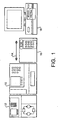
- a conventional chromatography system typically includes a solvent delivery system 12, a sample manager 10, a column 14, a detector 16, and a Data System 18
- the present invention provides a method of using automation technology for qualifying chromatography systems.
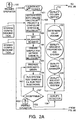
- a flow chart as shown in Fig. 2 illustrates the steps of an illustrative embodiment for performing a qualification according to the invention.
- the automated method is initiated by launching 101 a Millennium 32 Toolkit.
- the application retrieves the system information from an Oracle database 204 ( Fig. 3 ) and creates a Millennium project and configures 102 the system in accordance with Millennium as is known in the art.
- the application is then configured 102 according to the project selected.
- the configuration 102 of the application incorporates the control of various components of the application.
- the selection of the project type and the acquisition server are completed within the configuration 102 of the system.
- the chromatographic system is identified and the specific features of that system are confirmed.
- the presence of a column heater and the type of detector that is to be used for qualification are selected.
- the selection of the type of flow cell contained within the chromatographic system and the different instrument modules contained within the system are identified during the configuration 102 step and confirmed.
- the system is then validated 103 based upon the configuration 102 step.
- the application Based upon the qualification method selected during the configuration step 102 the application creates a matrix 104 with a specific sample and method queue within the Millennium 32 application.
- the methods that are selected during the configuration step 102 are specific for the various qualification methods within the illustrative embodiment.
- the matrix determines the specific chemistries and mathematical algorithms employed within a specific chromatography column.
- the trained operator 100 of the chromatography system prepares 105 the chromatograph for the automated qualification of the chromatography system.
- the trained operator 100 during the preparation step 105 verifies that the samples required for the entire qualification procedure are in the proper location in the proper carousels.
- the preparation 105 entails setting up the solvent manager, placing standard samples in the sample manager, and equilibrating the chromatographic column to ensure that the system is well equilibrated and ready for analysis.
- test injections 106 are run which verify that system preparation 105 is completed correctly. If the test injections 106 are within the specifications the trained operator 100 queues the running of the automated qualification process and the additional tests needed for qualification are then performed automatically without the need for trained operator 100 intervention. If the test injections 106 are not within specifications the preparation 105 of the chromatograph is repeated.
- Detector 108 it is critical that the qualification of Detector 108 is done first, since most of the remaining measurements are based on the accuracy and linearity of the detector.
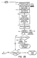
- the qualification of a solvent delivery system 109, a sample manager 110, a gradient proportioning system 111, and the delay volume 112 are conducted in the illustrative embodiment in a sequence 120 shown in Fig. 2 .
- This sequence 120 is not critical and in alternative embodiments the steps can be performed within a different sequence or performed substantially simultaneously.
- the qualification of the Column Heater 113 is optional since not all systems include this component.
- the Column Heater qualification 113 requires increasing the column temperature. It must therefore be done after the sequence 120 shown in Fig 2 . It is critical that the Column Heater qualification 113 be done after the sequence since chromatography systems usually have no active cooling mechanism.
- data is collected 114 that is generated by the automated qualification process and placed within an Oracle database 204 ( Fig. 3 ).
- the collected data.114 is processed 115 and the results are stored within the database 204 ( Fig. 3 ).
- the Millennium 32 201 ( Fig. 3 ) software then creates reports 116 in a format that is in conformance with regulatory requirements.
- a hard copy 117 of the reports 116 is printed for review 118 by the trained operator 100 of the chromatography system.
- the trained operator 100 confirms either the compliance 119 of the chromatography system or the failure 121 of the chromatography systems to perform within acceptable standards. Based on the generated reports 116 any deficiency within the system is identified and corrective action 122 is performed.
- FIG. 3 the automation, analysis, and generation of the above qualification method is accomplished within the illustrative embodiment by utilizing an add-on application 203 to the Millennium32 software 201 (Waters Corporation ).
- This add-on application 203 is built using the Millennium32 v.3.20 Toolkit Option 202 (Professional Edition, Waters Corporation ) and Microsoft Visual Basic 6.0 (Enterprise Edition, Microsoft Corporation ).
- the Millennium 32 version 3.20 Toolkit 202 consists of a Toolkit Server, a Toolkit Extensions Server and the ActiveX Processing Control. Millenium Toolkit 202 is described in detail in Toolkit Programmer's Reference Guide, P/N 71500016005, Revision A available from Waters Corporation Milford, MA .
- the Toolkit 202 is essentially an Applications Programming Interface (API) that defines the servers' objects and their methods and properties. Only pre-built objects available in Visual Basic 6.0 such as the form, the frame the command button, and the checkbox are used in the creation of the add-on 203 application.
- the add-on 203 application utilizes the Toolkit 202 and the underlying Milleniun 32 201 application running on Windows 98/Windows NT 200.
- the Millennium 32 Toolkit 202 is based upon component integration technology commercially available in the software industry, the Microsoft Component Object Model ("COM").
- the Toolkit Option 202 contains over 30 programmable COM objects that allow the use of development platforms such as Microsoft Visual Basic or Microsoft Office to create specialty applications that work interactively with the Millennium 32 201 software.
- the basic operation of the Millenium Toolkit 202 is in a wizard format.
- the resulting application 203 is compliant with the FDA's Electronic Records and Signatures Rule (21 CFR Part 11, Considered at the date when the present aplication was filed), which is a requirement for any laboratory operation under Good Laboratory Practice (“GLP”) or Good Manufacturing Practice (“GMP”) because Millennium 32 is compliant.
- GLP Good Laboratory Practice
- GMP Good Manufacturing Practice
- IQ data In order to record details such as IQ data a table is created in Millennium 32 Oracle database. Criteria associated with qualification data are the main make up of the table. A sequence is also created so that each record in the table is given a unique ID. Each type of record is version controlled and new versions will be recorded when new work is carried out. The records are stored in the database table. In this illustrative embodiment there is no delete functionality available. If there are discrepancies with the current IQ record then the trained operator 100 can re-write the details and store a new record. Instead of calling external SQL scripts the application uses the Command objects of a Data Environment Designer connection object. The data source is accessed using ActiveX Data Objects (ADO) from an OLE ® DB provider for Oracle.
- ADO ActiveX Data Objects
- ADO is designed as an easy-to-use application level interface to Microsoft's data access paradigm, OLE ® DB.
- OLE ® DB provides high-performance access to any data source, including relational and non-relational databases, email and file systems, text and graphics, custom business objects, and more.
- ADO is implemented within the illustrative embodiment for minimal network traffic in key Internet scenarios, and a minimal number of layers between the front-end and data source.
- the above methods provide a lightweight, high-performance interface.
- ADO is called using a familiar metaphor, the OLE ® Automation interface.
- OLE ® DB is a low-level interface that introduces a "universal" data access paradigm. That is, OLE ® DB is not restricted to ISAM, Jet or even relational data sources known in the art, but is capable of dealing with virtually any type of data regardless of its format or storage method. This versatility means that data in the illustrative embodiment can be accessed that resides in an Excel spreadsheet, text files, or even on a mail server such as Microsoft Exchange.
- Visual Basic 6.0 is utilized to increase the flexibility of OLE ® DB through ADO, programmer interface. Since OLE ® DB is not designed to be accessed directly from Visual Basic due to its complex interfaces, ADO encapsulates and exposes virtually all of OLE ® DB's functionality. Additionally, the Data Environment Designer provides an interactive, design time environment for creating programmatic run time data access. The property values are set for the Connection and the Command objects, write code to respond to ADO events, execute Commands, and create aggregates and hierarchies. The Data Environment objects are also placed onto forms or reports to create data-bound controls.
- the Data Environment designer is used to create a Data Environment object.
- the Data Environment object includes Connection and Command objects, groupings, and aggregates.
- the database is identified that contains the information for the run-time objective of creating a Data Report.
- Every Data Environment includes at least one Connection object.
- a Connection object represents a connection to a remote database that is used as a data source.
- the Data Environment designer Upon adding a Data Environment to the Visual Basic project, the Data Environment designer automatically includes a new connection, called Connection1.
- the configuration of the illustrative embodiment is such that the Data Environment opens the connection and obtains metadata from the connection, including database object names, table structures, and procedure parameters.
- the source for the data environment connection is defined using the data link properties dialog box.
- the Microsoft OLE ® DB provider for Oracle is the choice.
- the Command objects in this application are based on both the database table object and Structured Query Language (SQL) queries. Use is made of the fact that pre formatted Commands to carry out SQL queries can be revised at run time so that the changed query variables will cause data retrieval to change.
- SQL Structured Query Language
- the Microsoft Data Report designer is used in conjunction with the data source of the Data Environment designer, reports are created from the database qualification table for IQ. In addition to creating printable reports, one can also export the report to HTML or text files. As previously indicated query criteria change so to does the output of the report as the controls on the report are bound to the changed Command.
- the sample set methods to be chosen depends on the configuration 102 indicated by the trained operator 100 of the automated test system.
- the value properties are examined for the various qualification and text Checkboxes and the status indicated on the Configuration Frame. Whether a system is tested for Operational & Performance Qualification or full System Qualification there are different sample set methods to be used.
- the three variables "Detector Type”, "Temperature Control” and "Cell Type” influence the selection.
- a three dimensional sample set matrix/array with the above coordinates and containing various suffixes is provided within the software.
- the suffixes are concatenated with the chosen tests to be performed the result is a run sequence that can be passed to the instrument server. As shown in Fig.
- a series of test injections 106 is always used as part of the run as a precursor to successful qualification. Queuing the sample sets involves the initiation of a Toolkit Instrument object and using the run method with the names of the sample set methods. A timer cycle is used to enable the monitoring of Toolkit Instrument connection status. Each and every time a proposed run is to be queued the revision number for qualification attempts is incremented in the database table. The increment is also tied to the sample set name that appears in "Run Samples".
- the following chemistries and mathematical theories of the illustrative embodiment allow the above software to integrate the installation, operational and performance qualifications procedures into an automated system process by developing standards that are linear and therefore amenable to automated analysis.
- the quantitative analysis of a standard chromatogram as shown in Fig. 3a requires the association of a peak area (or height) with the mass or concentration of the analyte injected via an appropriate calibration curve constructed from the injections of standards.
- the principal parameters associated with a chromatogram are the retention times 301 and peak areas 302.
- the general metrics of instrumental analysis for the reported responses (retention times 301 and peak areas 302 ) are the basis of qualification for both manual and automated systems.
- the precision, accuracy, and linearity of retention times 301 and peak areas 302 are dependant upon factors discussed below.
- detector performance parameters that are measured in the present invention during the qualification of the detector which most directly affect the chromatograms are linear dynamic range and wavelength accuracy.
- Other detector performance parameters such as detector dispersion, noise, and drift are highly method dependent. Therefore, it is not useful to produce automation for those factors that are not universal in their impact.
- an illustration of the response curves for detectors demonstrates various linear dynamic range values.
- the value associated with each calibration curve is the absorbance at which the observed value is 95% of the value predicted by Beer's Law in accordance with an older ASTM protocol.
- the procedure calls for the drawing of the curved line which fits the data and the extrapolation of the initial slope. This is followed by an estimation of the 5% negative deviation point.
- the procedure is highly subjective and not adaptable for an automated test system.
- A ⁇ * b * C If the measured absorbance is divided by concentration, the apparent sensitivity is calculated.
- the apparent sensitivity, S is not constant over the dynamic range of the instrument, but the magnitude of the relative standard deviation (% RSD) of the sensitivity is a good measure of its degree of variation. If sensitivities are measured at values of absorbance which fall on both the linear and curved portions of the calibration curve, this RSD of the sensitivity becomes a good measure of linear dynamic range.
- Table 1 An example of such a calculation is shown hereinafter in Table 1.
- Table 1 Linear Dynamic Range Calculation Based on Sensitivity Concentration 2.5 AU 2.0 AU 1.6 AU S_2.5AU S_2.0AU S_1.6AU 5 0.499 0.498 0.495 0.0998 0.0995 0.0990 10 0.996 0.990 0.980 0.0996 0.0990 0.0980 15 1.486 1.467 1.436 0.0990 0.0978 0.0957 20 1.955 1.901 1.820 0.0978 0.0950 0.0910 25 2.371 2.241 0.0948 0.0896 30 2.678 0.0893 %RSD 4.21 4.22 3.72 Max AU 2.678 2.241 1.820
- the calculation is illustrated as such for the detector labeled 2.5 AU and the slope of the calibration curve has a relative standard deviation of only 4.21% for absorbances ⁇ 2.678.
- the detector labeled 1.6AU has a relative standard deviation of 3.72% for absorbance ⁇ 1.82.
- the apparent stray light for a given value of linear dynamic range (expressed as absorbance at which there is a 5% deviation from linearity) can be calculated.
- the control value for %RSD of the apparent sensitivity can be directly correlated to the design specification for a specific detector.
- a probe compound in the present invention is based on ensuring that the boundary conditions for Beer's Law are met.
- the above conditions are: spectral bandpass is small relative to peak width, dilute solution, constant refractive index, and simple chemical equilibrium.
- caffeine dissolved in water:methanol mixture and measured at 272 nm meets all of the criteria and is stable and available in high purity.
- the linear dynamic range of a detector is best measured at ⁇ max . This ensures that wavelength accuracy errors will not contribute to the measurement of linear dynamic range and that the spectral bandpass (slit width) of the detector will have minimum impact on the measurement. This is consistent with good spectroscopic practice.
- a series of samples which generate chromatographic peaks with heights ranging from 0.1 to 2.2 AU is injected into the chromatography system.
- the probe compound used for wavelength accuracy is also used for the measurement of linear dynamic range. This reduces the number of different samples and solvents required for qualification and ensures that the linear dynamic range is measured at ⁇ max .
- a probe compound In order to verify the wavelength accuracy of the detector during the qualification of the detector 108 of the present invention, a probe compound must be selected. Suitable probe compounds must not react with the column or any of the solvents. It also should have well defined characteristics that can be traced back to known (well characterized) standards. Most importantly, the UV spectrum of the probe compound must have at least two well resolved absorbance peaks which should be in the primary wavelength range of absorbance detectors (200 - 400 nm).
- Wavelength Accuracy Probe Compounds Name Solvent Wavelength(s) Note(s) Erbium (III) Perchlorate Water 255, 379, and 523 nm (all peaks are highly symmetric) NIST and ASTM traceable; multiple wavelengths over wide range; simple chemistry.
- Caffeine Water methanol 205 and 272 nm Two points covering primary wavelength range; easily automated.
- Anthracene Water Acetonitrile 252 nm Highly asymmetric peak at 252 mm; acceptable choice for detectors with small ( ⁇ 5 nm) spectral bandpass Holmium oxide Perchloric acid (10% in water) Multiple asymmetric peaks NIST traceable; best for detectors with cuvette accessory; requires very narrow ( ⁇ 2 nm) bandpass
- the first two compounds are the favored choices for wavelength accuracy measurements.
- Uracil is suitable for wavelength accuracy measurements for older detectors which have larger spectral bandpass values.
- One suitable probe compound is a solution of caffeine dissolved in methanol and water.
- a UV spectrum of the caffeine, methanol, and water solution has principal absorbance peaks at 205 nm and 272 nm.
- the observed wavelength of maximum absorbance (lambda max, ⁇ max ) must match the reference values within the detector specifications, typically ⁇ 1.5 to 2 nm.
- the OQ of the detector remains the same.
- the wavelength accuracy and linear dynamic range are the variables that either a manual qualification or as in the present invention an automated qualification need to access.
- Measurement of the linear dynamic range of a PDA detector ensures that both stray light and resolution are unchanged from the design parameters of the detector.
- Fluorescence detectors operate by irradiating the sample with light at an excitation wavelength ( ⁇ ex ) and measuring the intensity of the light emitted at the emission wavelength ( ⁇ em ).
- ⁇ ex excitation wavelength
- ⁇ em emission wavelength
- f ( ⁇ ) is the geometric collection efficiency of the detector
- g( ⁇ em ) is the photomultiplier's response at the emission wavelength
- ⁇ f is the quantum efficiency of the analyte
- P o ( ⁇ ex ) is the radiant power of the source at the excitation wavelength
- ⁇ is the molar absorbtivity
- b the path length
- C is the concentration of the analyte.
- Equation 1 can be simplified by combining constants and expanding the exponential term in a Taylor series to give Equation 2.
- Fluorescence F ⁇ constant * P o ⁇ ex * C
- Equation 1 This equation is correct only for small values of absorbance ( ⁇ 0.01) where the second order and higher terms of the Taylor series can be ignored. Examination of Equations 1 and 2 indicate that the following parameters will strongly influence the observed fluorescence signal. These parameters are as follows: excitation wavelength, emission wavelength, source intensity, the excitation wavelength, response characteristics of the photomultiplier tube, concentration of the analyte, and the quantum efficiency of the analyte.
- the first four factors are directly coupled to the detector while the last two factors are strongly assay dependent.
- the suitability of a fluorescence detector to perform chromatographic analysis can be determined by confirming wavelength accuracy for both the excitation and emission monochrometers and confirming that the signal to noise of a stable luminescence process meets an acceptance criteria. Because the absolute magnitude of the fluorescence signal is directly proportional to the source intensity which will vary as the lamp ages, it is not possible to benchmark performance to the peak height under specific gain conditions. A more measurable approach for the determination of the condition of the detector is to measure the signal to noise ratio for a well-known luminescence signal.
- the Raman shift of water provides a convenient test probe for fluorescence detectors.
- most water molecules scatter the light elastically, i . e ., with no transfer of energy.
- a small fraction of the water molecules absorb sufficient energy and re-emit the photon at a lower frequency.
- the excitation light is at 350 nm, the Raman scattering is observed at 397 nm.
- the signal to noise ratio of the emission peak at 397 nm and its location at 397 nm confirm the suitability of the detector with respect to response and wavelength accuracy.
- the observed signal to noise ratio for the Raman band of water will reflect the source intensity, the purity of the water used for the measurements (HPLC grade water is appropriate), and the signal processing (including filtering, spectral bandpass of both monochrometers, and the illuminated volume of the flow cell).
- the Raman signal to noise ratio should meet or exceed the manufacturers' specification. If either the excitation or emission monochrometer's wavelength accuracy can be independently verified, the relationship between the observed ⁇ max of the Raman band (397 nm with 350 nm excitation) can be used to verify the remaining monochrometer. If the flow cell is removed and the photomultiplier gain is kept small, the presence of Hg emission lines in the light from fluorescent room lights can be used to verify the wavelength accuracy of the emission monochrometer.
- Equation 1 Verification of linear dynamic range for a fluorescence detector is not required because Equation 1 is inherently non-linear and behaves linearly only under specific conditions.
- the inner filter effect occurs when the sample (or its solvent) absorbs a portion of the excitation energy in a portion of the flow cell which is not imaged onto the emission monochrometer. The result is that the radiant energy is decreased without a concurrent increase in the measured emission intensity. If the absorbance spectrum overlaps the emission spectrum, some of the photons emitted by the analyte molecules will not be observed. The magnitude of both of these effects is dependent upon the analyte concentration. Consequently, the linear dynamic range of a specific assay will be highly dependent upon the specific concentration range and solution conditions and is verified as part of system suitability and calibration for this particular assay within the automated qualification system.
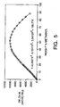
- Refractive index detectors are bulk property detectors, i.e., they respond to differences in the refractive index of the mobile phase when the analyte is eluted from the column. Consequently, it is necessary to stabilize the refractive index of the mobile phase in order to achieve good signal to noise ratios when small analyte peaks are eluted. Testing of the refractive index detector is, of necessity, a system level test and cannot be performed at a unit level. The change in refractive index with concentration is not necessarily a linear phenomenon as illustrated by the water methanol data shown in Fig. 5 .
- the detector linearity, injector linearity, injector area precision, retention time precision and flow rate accuracy with DRI is performed using pre-mixed mobile phase.
- the pre-mixed mobile phase allows the stable baselines required for unambiguous integration.
- the performance qualification of a chromatograph which uses an absorbance detector is an assessment of baseline performance which the majority of chromatographic analyses will require. Because absorbance detectors have a wide linear dynamic range, the system performance parameters to be determined are isocratic retention time precision, peak area precision, and system linearity.
- a simple reverse phase separation (C18 column with methanol:water mobile phase) of stable analytes which cover a range of moderate values of k' is utilized in the present invention.
- a mixture of uracil and caffeine is used to generate chromatograms with a void marker (uracil) and a well-resolved retained peak suitable for quantitation.
- the mobile phase can be pre-mixed or mixed on-line if a gradient system is used.
- Table 4 lists the appropriate control values for a general HPLC system. Table 4. Control Values Peak Retention Time RSD(%) Area Precision RSD(%) Height Precision RSD(%) Linearity (R 2 ) Uracil 1.5 1.5 1.5 N/A Caffeine 1.0 1.0 1.0 >0.999
- the performance qualification of a fluorescence detector in the present invention is accomplished according to the following method.
- Measurement of flow rate accuracy and injection volume accuracy in the manual qualification of systems is generally based on measuring the time required to fill a volumetric flask (flow rate accuracy) or by weighing the mass removed from the sample vial (injection accuracy). Both techniques are manual and, it is desirable, in the illustrative embodiment to conduct an analysis that is subject to automation and less prone to human error.
- the void volume of a chromatographic column is that portion of the column's nominal volume which is occupied by mobile phase, it includes the inter-particle and intra-particle volume. It is usually measured by adding an unretained small molecule, such as acetone, uracil, sodium nitrate, etc. , to the sample mixture and measuring the product of the flow rate and apparent "retention time.” Equation 3 relates the void volume to column parameters and flow rate.
- Equation 5 is illustrated.
- the calculation has the advantage of computing a volumetric flow rate error term which includes contributions over the working range of the solvent delivery system and does not include contributions from the compositional errors of the pump because the peak is unretained.
- an appropriate sample of a non-retained compound (such as uracil or sodium nitrate) is eluted at several flow rates which span the active flow rate range.
- the unretained component is eluted at the void volume of the column.
- Fig. 8 illustrates the above approach.
- the x-intercept is an estimate of the volumetric error of the quantity delivered and includes contributions over the full dynamic range of the instrument and estimates the systematic error in the quantity delivered to the column by the sample manager 110. This makes the approach appropriate to sample managers in which the sample is contained within the sample needle as well as those which transfer the sample to a sample loop.
- the values of the x-intercepts establish an error budget which can then be applied to the assay requirements.
- the 0.050 mL/min error is a 5% error at 1.0 mL/min, but is only 2% at 2 mL/min.
- the 0.050 ⁇ L error contributes a 2 parts per thousand error at 25 ⁇ L and 1% at 5 ⁇ L. This error budget should then be a part of establishing the system suitability criteria for a specific assay.
- the qualification of the gradient proportioning system 111 is the measurement of the compositional accuracy based on shifts in retention time with small changes in composition; the system noise will be greater, but retention times are not strongly impacted by baseline noise if the signal to noise ratio is large.
- the compositional accuracy measures the degree to which the solvent management system can generate a specific solvent mixture. To determine the compositional accuracy, inject the same volumes of samples while using different combinations of reservoirs in the chromatography system. The relative standard deviation (%RSD) of the retention times is measured and those of caffeine should be fairly consistent.
- the qualification standard requires the relative standard deviation to be less than or equal to 2%.
- the qualification of the delay volume 112 of the solvent management system is the volume of mobile phase that separates the gradient forming device from the column inlet. Ideally, the delay volume should be scaled to the void volume of the chromatographic column to ensure method transferability and efficiency.
- the delay volume of a gradient solvent delivery system was measured by the volume required for a step change in mobile phase composition using a suitable marker compound (such as acetone or propyl paraben) to arrive at the inlet connection of the column. The column needed to be removed in such measurements. Both threshold-based and first derivative-based calculations have been used to determine the arrival time.
- the delay volume of a gradient chromatography system is the volume contained in the solvent delivery system from the point at which the gradient is formed (the gradient proportioning valve in a low pressure gradient system) or from the first mixing "tee" where the solvents are combined (high pressure gradient system) to the column's inlet. Its significance arises from the need to qualify the gradient proportioning system 111 to ensure that the delay volume is delivered to the column before the gradient change in mobile phase composition begins. It is a temporal offset in the gradient chromatogram. If all of the components of the sample are strongly retained in the initial conditions of the gradient, it is simply overhead that increases the separation time and the time required to re-equilibrate the column prior to the next injection.
- a mixture of an unretained and strongly retained compounds (such as uracil and octanophenone) are injected and the mobile phase composition is changed in a single step from the initial conditions to 100% organic modifier.
- the unretained compound will have a retention volume equal to the void volume of the column plus the tubing which connects the column to the injector and detector.
- the strongly retained compound will initially be focused at the column inlet and subsequently eluted as an unretained component after the step to 100% organic modifier.
- the retention volume of the strongly retained compound will be the sum of the delay volume, the volume of the connecting tubing, the void volume of the column, and the volume of solvent pumped at the initial composition.
- the qualification of the column heater 113 is essential in those systems that contain column heaters.
- the qualification of a column heater 113 is important in order to insure that the column heater can consistently provide a set temperature because retention times and mobile phase viscosity are both strongly dependent upon temperature.
- the performance of column heaters in a manual qualification system is determined by placing calibrated thermocouples or thermistors at, or near, the control point of the column heater and measuring the difference between the set temperature and the observed temperature. This approach requires the use of external meters to read the output of the thermocouple and is highly subjective because it depends upon the accurate location of the thermocouple at the control point of the column heater. Additionally, while this approach confirms that the column heater is controlling the set point, it does not measure the effectiveness of the column heater at actually heating the column.
- the approach set forth below has the advantage of requiring no additional devices, no manual data entry, and it is not dependent upon the location of the temperature probe for its accuracy.
- all qualification steps will be performed at a temperature which is about 10°C (degrees Celsius) greater than ambient laboratory temperature.
- the average retention time measured for the injections used for the measurement of the sample manager's precision are a good estimate of the retention time at this base temperature.
- the column heater is subsequently set to a temperature which is 20°C greater than ambient. After the column is equilibrated at this new higher temperature a set of injections are made using the same sample and conditions for the determination of sample manager precision.
- the decrease in retention time is dependant upon the nature of the probe compound the stationary phase and the mobile phase. A decrease of ⁇ 0.18 minutes has been empirically observed for the conditions chosen in this procedure. It is based on the "normal/intended" use of the column heater within the chromatograph
- V R V o * 1 + k ⁇
- V o the column's void volume
- k' the capacity factor for the analyte
- the capacity factor is related to the equilibrium constant for the partitioning of the analyte between the stationary phase and mobile phase by Equation 7.
- the equilibrium constant has the usual thermodynamic dependence upon temperature as given by Equation 8.
- FIG. 10 A plot of Ink' vs . 1/T (°K) is linear with a slope of (- ⁇ G o /R) and an intercept of ln ⁇ .
- An example of two sets of retention time measurements as a function of column temperature (from 30°C to 60°C) is shown in Fig. 10 . While equations 6 and 8 predict a non-linear dependence of retention time with certain temperatures, Figure 11 demonstrates that there is a reasonable degree of linearity over a short range of temperature
- qualification procedures could be implemented such as to qualify the individual modules of a chromatography system in the event repairs must be done, or the like.
- qualification could be effected by making the preparation of the chromatography system completely automated.
Landscapes
- Physics & Mathematics (AREA)
- Health & Medical Sciences (AREA)
- Life Sciences & Earth Sciences (AREA)
- Chemical & Material Sciences (AREA)
- Analytical Chemistry (AREA)
- Biochemistry (AREA)
- General Health & Medical Sciences (AREA)
- General Physics & Mathematics (AREA)
- Immunology (AREA)
- Pathology (AREA)
- Treatment Of Liquids With Adsorbents In General (AREA)
- Automatic Analysis And Handling Materials Therefor (AREA)
Claims (12)
- Procédé automatisé pour la qualification d'un système de chromatographie comportant un détecteur (108), un système de distribution de solvants (109), un gestionnaire d'échantillons (110), et une colonne, et un système de données, comportant les étapes consistant à :préparer le système de chromatographie pour s'assurer que les échantillons, les solvants, et la colonne sont prêts en vue d'une analyse,qualifier le détecteur (108) pour garantir l'opération selon des paramètres de détection spécifiés,qualifier le système de distribution de solvants (109) pour garantir l'opération selon des paramètres de distribution de solvants spécifiés,qualifier le gestionnaire d'échantillons (110) pour garantir l'opération selon des paramètres de distribution d'échantillons spécifiés,utiliser une analyse de régression pour calculer les performances d'exactitude, linéarité, et précision du système de chromatographie, l'analyse de régression comportant :(1) la précision du débit et la linéarité du temps de rétention d'un composant non-retenu par rapport au débit volumétrique du système de distribution de solvants, et/ou(2) la précision du volume d'injection et la linéarité du gestionnaire d'échantillons.
- Procédé automatisé pour la qualification d'un système de chromatographie selon la revendication 1, dans lequel ledit système de chromatographie inclut un système de dosage de gradient (111), comportant en outre l'étape consistant à qualifier le système de dosage de gradient pour garantir l'opération selon des paramètres de dosage de gradient spécifiques.
- Procédé automatisé pour la qualification d'un système de chromatographie selon la revendication 1, dans lequel ledit système de chromatographie inclut un volume de retard (112) comportant en outre l'étape consistant à qualifier un volume de retard du système de chromatographie pour garantir l'opération selon des paramètres de volume de retard spécifiques.
- Procédé automatisé pour la qualification d'un système de chromatographie selon la revendication 1, dans lequel ledit système de chromatographie inclut un réchauffeur de colonne (113), comportant en outre l'étape consistant à qualifier le réchauffeur de colonne pour garantir l'opération selon des paramètres température de colonne spécifiques.
- Procédé selon la revendication 1, dans lequel ledit détecteur est un détecteur d'absorbance.
- Procédé selon la revendication 1, dans lequel ledit détecteur est un détecteur à réseau de photodiodes.
- Procédé selon la revendication 1, dans lequel ledit détecteur est un détecteur de fluorescence.
- Procédé selon la revendication 1, dans lequel ledit détecteur est un détecteur d'indice de réfraction.
- Procédé selon la revendication 1, dans lequel ledit procédé pour la qualification utilise des signatures électroniques et leurs enregistrements électroniques associés pour sécuriser lesdits enregistrements.
- Procédé selon la revendication 9, incluant en outre l'étape consistant à générer un rapport pour confirmer la conformité du système de chromatographie.
- Procédé selon la revendication 10, incluant en outre l'étape consistant à réviser ledit rapport pour confirmer la conformité du système de chromatographie.
- Procédé selon la revendication 10, dans lequel ledit rapport est un rapport sur papier.
Applications Claiming Priority (3)
| Application Number | Priority Date | Filing Date | Title |
|---|---|---|---|
| US730126 | 1991-07-15 | ||
| US09/730,126 US6456955B1 (en) | 2000-12-05 | 2000-12-05 | Automated test protocol |
| PCT/US2001/046791 WO2002047009A1 (fr) | 2000-12-05 | 2001-12-05 | Protocole de test automatise |
Publications (3)
| Publication Number | Publication Date |
|---|---|
| EP1342202A1 EP1342202A1 (fr) | 2003-09-10 |
| EP1342202A4 EP1342202A4 (fr) | 2008-08-06 |
| EP1342202B1 true EP1342202B1 (fr) | 2013-11-06 |
Family
ID=24934021
Family Applications (1)
| Application Number | Title | Priority Date | Filing Date |
|---|---|---|---|
| EP01995391.8A Expired - Lifetime EP1342202B1 (fr) | 2000-12-05 | 2001-12-05 | Protocole de test automatise |
Country Status (5)
| Country | Link |
|---|---|
| US (1) | US6456955B1 (fr) |
| EP (1) | EP1342202B1 (fr) |
| JP (3) | JP2004515770A (fr) |
| AU (1) | AU2002225956A1 (fr) |
| WO (1) | WO2002047009A1 (fr) |
Families Citing this family (57)
| Publication number | Priority date | Publication date | Assignee | Title |
|---|---|---|---|---|
| US6971059B1 (en) * | 2000-11-28 | 2005-11-29 | Agilent Technologies, Inc. | Chromatographic or spectroscopic reports with hyperlinks to allow direct access to external references |
| US6862488B2 (en) * | 2002-07-05 | 2005-03-01 | Validation Commerce, Llc | Automated validation processing and workflow management |
| US7650512B2 (en) * | 2003-11-18 | 2010-01-19 | Oracle International Corporation | Method of and system for searching unstructured data stored in a database |
| US7966493B2 (en) * | 2003-11-18 | 2011-06-21 | Oracle International Corporation | Method of and system for determining if an electronic signature is necessary in order to commit a transaction to a database |
| US20050108211A1 (en) * | 2003-11-18 | 2005-05-19 | Oracle International Corporation, A California Corporation | Method of and system for creating queries that operate on unstructured data stored in a database |
| US8782020B2 (en) * | 2003-11-18 | 2014-07-15 | Oracle International Corporation | Method of and system for committing a transaction to database |
| US7600124B2 (en) * | 2003-11-18 | 2009-10-06 | Oracle International Corporation | Method of and system for associating an electronic signature with an electronic record |
| US7694143B2 (en) * | 2003-11-18 | 2010-04-06 | Oracle International Corporation | Method of and system for collecting an electronic signature for an electronic record stored in a database |
| US7930053B2 (en) * | 2003-12-23 | 2011-04-19 | Beacons Pharmaceuticals Pte Ltd | Virtual platform to facilitate automated production |
| US7318900B2 (en) * | 2004-02-25 | 2008-01-15 | Varian, Inc. | Chromatography system and method |
| JP4661136B2 (ja) * | 2004-08-31 | 2011-03-30 | 株式会社島津製作所 | 測定装置用制御・データ処理装置及びプログラム |
| US8380441B2 (en) * | 2004-11-30 | 2013-02-19 | Agilent Technologies, Inc. | Systems for producing chemical array layouts |
| US20060115822A1 (en) * | 2004-11-30 | 2006-06-01 | Webb Peter G | Systems and methods for probe design |
| US20060116827A1 (en) * | 2004-11-30 | 2006-06-01 | Webb Peter G | Systems and methods for producing chemical array layouts |
| US8230042B2 (en) | 2005-04-19 | 2012-07-24 | International Business Machines Corporation | Policy based auditing of workflows |
| US7440863B2 (en) * | 2005-04-29 | 2008-10-21 | Agilent Technologies, Inc. | Integrated tool for compliance testing within an enterprise content management system |
| US7890285B2 (en) * | 2005-04-29 | 2011-02-15 | Agilent Technologies, Inc. | Scalable integrated tool for compliance testing |
| US20070021919A1 (en) * | 2005-07-19 | 2007-01-25 | Leproust Eric M | Silico design of chemical arrays |
| US7635433B2 (en) * | 2005-08-26 | 2009-12-22 | Agilent Technologies, Inc. | System and method for feature alignment |
| US20070143029A1 (en) * | 2005-12-15 | 2007-06-21 | Nelson Charles F | Systems and methods for producing chemical array layouts |
| US20070148658A1 (en) * | 2005-12-23 | 2007-06-28 | Nelson Charles F | Systems and methods for biopolymeric probe design using graphical representation of a biopolymeric sequence |
| US20080004814A1 (en) * | 2006-06-29 | 2008-01-03 | Nelson Charles F | Systems and methods for probe annotation |
| US20080005142A1 (en) * | 2006-06-29 | 2008-01-03 | Nelson Charles F | Systems and methods for array content information exchange |
| US20080027654A1 (en) * | 2006-07-28 | 2008-01-31 | Nelson Charles F | Systems and methods for probe design |
| US20080040047A1 (en) * | 2006-07-28 | 2008-02-14 | Nelson Charles F | Systems and Computer Program Products for Probe Set Design |
| US20080027653A1 (en) * | 2006-07-28 | 2008-01-31 | Nelson Charles F | Systems and methods for probe qualification |
| US20080027655A1 (en) * | 2006-07-28 | 2008-01-31 | Nelson Charles F | Systems and methods for probe selection |
| US20080228409A1 (en) * | 2006-07-28 | 2008-09-18 | Nelson Charles F | Systems and methods for probe design based on experimental parameters |
| WO2008025887A1 (fr) * | 2006-08-28 | 2008-03-06 | Novasep | Procede d'enrichissement d'un ou plusieurs composes d'un melange utilisant une phase mobile liquide contenant un gaz |
| US7668680B2 (en) * | 2007-03-02 | 2010-02-23 | Agilent Technologies, Inc. | Operational qualification by independent reanalysis of data reduction patch |
| US20080243396A1 (en) * | 2007-03-28 | 2008-10-02 | Webb Peter G | Systems and methods for sub-genomic region specific comparative genome hybridization probe selection |
| US20090089329A1 (en) * | 2007-09-28 | 2009-04-02 | Nelson Iii Charles F | Systems and methods for the dynamic generation of repeat libraries for uncharacterized species |
| CA2712732C (fr) * | 2008-01-25 | 2018-11-27 | Biogen Idec Ma Inc. | Systeme automatise et procede pour surveiller la performance d'une colonne de chromatographie, et leurs applications |
| JP5266862B2 (ja) * | 2008-04-30 | 2013-08-21 | 株式会社島津製作所 | 分析システム |
| CA2728741A1 (fr) * | 2008-06-25 | 2009-12-30 | Ge Healthcare Bioscience Bioprocess Corp. | Procedure d'installation automatisee d'un circuit de flux jetable |
| JP4915623B2 (ja) * | 2008-08-19 | 2012-04-11 | 西川計測株式会社 | 化学剤検出・定量方法 |
| CA2764934A1 (fr) * | 2009-06-24 | 2010-12-29 | F. Hoffmann-La Roche Ag | Caracterisation d'equipement chromatographique reutilisable |
| WO2012040178A1 (fr) | 2010-09-24 | 2012-03-29 | Waters Technologies Corporation | Techniques pour les tests automatiques de logiciels |
| WO2012079907A2 (fr) * | 2010-12-17 | 2012-06-21 | F. Hoffmann-La Roche Ag | Commande automatique d'une pluralité de dispositifs d'un procédé de séparation et de détection pour une analyse quantitative d'échantillons |
| EP2681668A4 (fr) * | 2011-03-04 | 2014-12-24 | Waters Technologies Corp | Techniques de notification d'événement |
| US10401334B2 (en) * | 2011-07-15 | 2019-09-03 | Shimadzu Corporation | Control system and program for liquid chromatograph |
| JP5900002B2 (ja) * | 2012-02-17 | 2016-04-06 | 株式会社島津製作所 | 分析装置制御システム及びプログラム |
| JP2014029282A (ja) | 2012-07-31 | 2014-02-13 | Shimadzu Corp | 分析装置バリデーションシステム及び該システム用プログラム |
| US9442098B2 (en) * | 2012-08-02 | 2016-09-13 | Waters Technologies Corporation | Chromatographic system quality control reference materials |
| JP2014206510A (ja) * | 2013-04-15 | 2014-10-30 | 株式会社堀場エステック | ガスクロマトグラフ用データ処理装置、データ処理方法、及び、データ処理用プログラム |
| EP4621574A3 (fr) * | 2015-03-31 | 2025-11-26 | Waters Technologies Corporation | Module de vanne à mode d'injection multiple |
| CN104914760B (zh) * | 2015-05-12 | 2017-11-14 | 山东成泰化工有限公司 | 一种色谱分析数据报送控制方法及装置 |
| JP7203771B2 (ja) * | 2017-06-19 | 2023-01-13 | ウオーターズ・テクノロジーズ・コーポレイシヨン | 科学機器システムにおける平衡化及び安定性を判定する技術 |
| JP6992892B2 (ja) * | 2018-06-07 | 2022-01-13 | 株式会社島津製作所 | グラジエント送液の濃度正確性を測定する方法及びその方法を実行する機能を有する液体クロマトグラフ |
| CN112585472A (zh) * | 2018-08-30 | 2021-03-30 | 株式会社岛津制作所 | 验证装置、验证方法及验证程序 |
| EP3885763B1 (fr) * | 2018-11-20 | 2026-02-25 | Hitachi High-Tech Corporation | Appareil d'analyse ayant une pluralité de chromatographes liquides, et son procédé d'analyse |
| JP7226522B2 (ja) * | 2019-03-13 | 2023-02-21 | 株式会社島津製作所 | 液体クロマトグラフィー分析システム |
| US20240085384A1 (en) * | 2021-01-26 | 2024-03-14 | Shimadzu Corporation | Chromatograph |
| JP7585833B2 (ja) * | 2021-02-03 | 2024-11-19 | 株式会社島津製作所 | 適格性評価装置および適格性評価方法 |
| GB2605397B (en) | 2021-03-30 | 2024-06-26 | Agilent Technologies Inc | Using multi-component test sample for determining real parameter value of sample separation |
| JP2023079387A (ja) * | 2021-11-29 | 2023-06-08 | 株式会社島津製作所 | 文書作成システム、サーバ、および方法 |
| US20260079136A1 (en) | 2024-09-18 | 2026-03-19 | Dionex Softron Gmbh | Method for optimizing a liquid chromatography system and system for liquid chromatography |
Citations (2)
| Publication number | Priority date | Publication date | Assignee | Title |
|---|---|---|---|---|
| US4740903A (en) * | 1984-05-15 | 1988-04-26 | Sumitomo Chemical Co., Ltd. | Data processing system for chromatography |
| US5670379A (en) * | 1992-05-19 | 1997-09-23 | Hitachi, Ltd. | Chromatograph system and method of use |
Family Cites Families (25)
| Publication number | Priority date | Publication date | Assignee | Title |
|---|---|---|---|---|
| US4674323A (en) * | 1985-07-31 | 1987-06-23 | The Dow Chemical Company | Self-diagnostic gel permeation/size exclusion chromatograph |
| JPH01174965A (ja) * | 1987-12-29 | 1989-07-11 | Sumitomo Chem Co Ltd | 連続自動クロマトグラフ分析システム |
| EP0359319A3 (fr) * | 1988-09-14 | 1991-10-23 | Philips Electronics Uk Limited | Chromatographie |
| EP0359320A3 (fr) * | 1988-09-14 | 1991-10-23 | Philips Electronics Uk Limited | Chromatographe |
| DE68913730T2 (de) * | 1989-06-23 | 1994-06-23 | Hewlett Packard Gmbh | Vorrichtung und Verfahren zur Optimierung der flüssig-chromatographischen Trennung einer Probe. |
| JPH03269258A (ja) * | 1990-03-19 | 1991-11-29 | Hitachi Ltd | クロマトグラフ用データ処理装置 |
| JPH0490002A (ja) * | 1990-08-03 | 1992-03-24 | Hitachi Ltd | クロマトグラフ制御システム |
| JP3074869B2 (ja) * | 1991-11-26 | 2000-08-07 | 株式会社島津製作所 | クロマトグラフ用データ処理装置 |
| US5360320A (en) * | 1992-02-27 | 1994-11-01 | Isco, Inc. | Multiple solvent delivery system |
| JPH07120451A (ja) * | 1993-10-27 | 1995-05-12 | Shimadzu Corp | カラム自動評価機能を備えたクロマトグラフ |
| US5605317A (en) * | 1994-03-21 | 1997-02-25 | Sapphire Engineering, Inc. | Electro-magnetically operated valve |
| JP2764855B2 (ja) * | 1994-03-30 | 1998-06-11 | 消防庁長官 | 架梯装置 |
| DE19540527A1 (de) * | 1995-10-31 | 1997-05-07 | Hewlett Packard Gmbh | Vorrichtung zur Erkennung austauschbarer Teile in analytischen Meßgeräten |
| JP3222759B2 (ja) * | 1996-04-08 | 2001-10-29 | 株式会社日立製作所 | 液体クロマトグラフ |
| JP3668594B2 (ja) * | 1997-07-05 | 2005-07-06 | 株式会社コスモ総合研究所 | ガスクロマトグラフにおける保持時間の補正関数作成方法、ガスクロマトグラフを用いた液状混合物の分析方法、およびガスクロマトグラフ |
| US6112161A (en) * | 1997-09-17 | 2000-08-29 | Hewlett-Packard | Method, apparatus, and article of manufacture for enhanced intergration of signals |
| JPH11137907A (ja) * | 1997-11-11 | 1999-05-25 | Moore Kk | 脱気装置 |
| US6064945A (en) * | 1998-02-20 | 2000-05-16 | Waters Investments Limited | System and method for determining molecular weight and intrinsic viscosity of a polymeric distribution using gel permeation chromatography |
| SE9801949D0 (sv) * | 1998-06-02 | 1998-06-02 | Astra Ab | Process control |
| JP3670851B2 (ja) * | 1998-07-21 | 2005-07-13 | アクト・サイエンス株式会社 | 液体クロマトグラフィー用送液ポンプ |
| JP3414311B2 (ja) * | 1998-08-26 | 2003-06-09 | 株式会社島津製作所 | 分析装置の検出装置 |
| US6210465B1 (en) * | 1999-03-17 | 2001-04-03 | Agilent Technologies, Inc. | Method for identification of components within a known sample |
| JP2000275253A (ja) * | 1999-03-26 | 2000-10-06 | Horiba Ltd | 分析計の妥当性確認方法、妥当性確認機能を有する分析計および分析計の妥当性確認プログラムを記録した記録媒体 |
| US6296771B1 (en) * | 1999-04-02 | 2001-10-02 | Symyx Technologies, Inc. | Parallel high-performance liquid chromatography with serial injection |
| US20020010566A1 (en) * | 2000-04-11 | 2002-01-24 | Chester Thomas Lee | Methods for modeling, predicting, and optimizing high performance liquid chromatography parameters |
-
2000
- 2000-12-05 US US09/730,126 patent/US6456955B1/en not_active Expired - Lifetime
-
2001
- 2001-12-05 AU AU2002225956A patent/AU2002225956A1/en not_active Abandoned
- 2001-12-05 JP JP2002548658A patent/JP2004515770A/ja active Pending
- 2001-12-05 EP EP01995391.8A patent/EP1342202B1/fr not_active Expired - Lifetime
- 2001-12-05 WO PCT/US2001/046791 patent/WO2002047009A1/fr not_active Ceased
-
2007
- 2007-01-25 JP JP2007014417A patent/JP4921993B2/ja not_active Expired - Fee Related
-
2008
- 2008-09-29 JP JP2008250751A patent/JP5291421B2/ja not_active Expired - Fee Related
Patent Citations (2)
| Publication number | Priority date | Publication date | Assignee | Title |
|---|---|---|---|---|
| US4740903A (en) * | 1984-05-15 | 1988-04-26 | Sumitomo Chemical Co., Ltd. | Data processing system for chromatography |
| US5670379A (en) * | 1992-05-19 | 1997-09-23 | Hitachi, Ltd. | Chromatograph system and method of use |
Also Published As
| Publication number | Publication date |
|---|---|
| WO2002047009A1 (fr) | 2002-06-13 |
| JP4921993B2 (ja) | 2012-04-25 |
| US20020107652A1 (en) | 2002-08-08 |
| JP2004515770A (ja) | 2004-05-27 |
| EP1342202A1 (fr) | 2003-09-10 |
| JP5291421B2 (ja) | 2013-09-18 |
| JP2007101564A (ja) | 2007-04-19 |
| AU2002225956A1 (en) | 2002-06-18 |
| EP1342202A4 (fr) | 2008-08-06 |
| US6456955B1 (en) | 2002-09-24 |
| JP2009031305A (ja) | 2009-02-12 |
Similar Documents
| Publication | Publication Date | Title |
|---|---|---|
| US6456955B1 (en) | Automated test protocol | |
| Jadhav et al. | Implementation of QbD approach to the analytical method development and validation for the estimation of propafenone hydrochloride in tablet dosage form | |
| US7998742B2 (en) | Fluorescent assay | |
| Dorschel et al. | LC detectors: evaluation and practical implications of linearity | |
| EP1627298B1 (fr) | Modelisation compositionnelle et procede d'analyse de donnees de pyrolyse | |
| EP1349879B1 (fr) | Systeme et procede servant a determiner le poids moleculaire et la viscosite intrinseque d'une distribution polymere a l'aide d'une chromatographie par permeation de gel | |
| JPH0835961A (ja) | クロマトグラフィ法で分離したサンプルの各スライスにおける測定に関連する変数の標準偏差を決定する方法 | |
| Mehta | The validation criteria for analytical methods used in pharmacy practice research | |
| Furman et al. | Validation of computerized liquid chromatographic systems | |
| Zander et al. | Large‐Volume Injection and Assessment of Reference Standards for n‐Alkane δD and δ13C Analysis via Gas Chromatography Isotope Ratio Mass Spectrometry | |
| US20030109061A1 (en) | Sample introduction system | |
| Espinosa-Peña et al. | Simulated distillation yield curves in heavy crude oils: A comparison of precision between ASTM D-5307 and ASTM D-2892 physical distillation | |
| Kristiansen et al. | Traceability and uncertainty in analytical measurements | |
| Halvorson et al. | Axial dispersion of solute zones in gel permeation chromatography | |
| Riley | Statistical parameters and analytical figures of merit | |
| Burke et al. | Complete equation for the measurement of organic molecules using stable isotope labeled internal standards, exact matching, and mass spectrometry | |
| US7310149B2 (en) | Systems and methods for measurement of properties of small volume liquid samples | |
| Korolev et al. | Estimation of the petroleum product knock rating by regression analysis of near-infrared absorption spectra | |
| Ross | Instrumental validation in capillary electrophoresis and checkpoints for method validation | |
| Burgess et al. | It’s qualification, but not as we know It | |
| Murby et al. | Production and certification of a freeze-dried reference material for human urinary steroids to ensure quality of longitudinal profiling data | |
| Pawar et al. | Calibration Of Analytical Instruments: A Review | |
| González | Practical Considerations on Indirect Calibration in | |
| Ivanova et al. | Assessing Errors and Uncertainties in the Instrumental Dating of Document Requisites by the Relative Content of Volatile Solvents in Strokes | |
| Crandall | How to specify, design and maintain online process analyzers |
Legal Events
| Date | Code | Title | Description |
|---|---|---|---|
| PUAI | Public reference made under article 153(3) epc to a published international application that has entered the european phase |
Free format text: ORIGINAL CODE: 0009012 |
|
| 17P | Request for examination filed |
Effective date: 20030516 |
|
| AK | Designated contracting states |
Kind code of ref document: A1 Designated state(s): AT BE CH CY DE DK ES FI FR GB GR IE IT LI LU MC NL PT SE TR |
|
| AX | Request for extension of the european patent |
Extension state: AL LT LV MK RO SI |
|
| RBV | Designated contracting states (corrected) |
Designated state(s): DE FR GB |
|
| A4 | Supplementary search report drawn up and despatched |
Effective date: 20080707 |
|
| RIC1 | Information provided on ipc code assigned before grant |
Ipc: B01D 53/02 20060101ALI20080702BHEP Ipc: G01N 30/88 20060101ALI20080702BHEP Ipc: G01N 30/02 20060101ALI20080702BHEP Ipc: G06F 19/00 20060101AFI20020617BHEP |
|
| 17Q | First examination report despatched |
Effective date: 20080919 |
|
| RAP1 | Party data changed (applicant data changed or rights of an application transferred) |
Owner name: WATERS TECHNOLOGIES CORPORATION |
|
| GRAP | Despatch of communication of intention to grant a patent |
Free format text: ORIGINAL CODE: EPIDOSNIGR1 |
|
| INTG | Intention to grant announced |
Effective date: 20130614 |
|
| RIN1 | Information on inventor provided before grant (corrected) |
Inventor name: ANDREWS, RICHARD, WAYNE Inventor name: CORBIN, VIRGINIA, L. |
|
| GRAS | Grant fee paid |
Free format text: ORIGINAL CODE: EPIDOSNIGR3 |
|
| GRAA | (expected) grant |
Free format text: ORIGINAL CODE: 0009210 |
|
| AK | Designated contracting states |
Kind code of ref document: B1 Designated state(s): DE FR GB |
|
| REG | Reference to a national code |
Ref country code: GB Ref legal event code: FG4D |
|
| REG | Reference to a national code |
Ref country code: DE Ref legal event code: R096 Ref document number: 60148432 Country of ref document: DE Effective date: 20140102 |
|
| REG | Reference to a national code |
Ref country code: DE Ref legal event code: R097 Ref document number: 60148432 Country of ref document: DE |
|
| PLBE | No opposition filed within time limit |
Free format text: ORIGINAL CODE: 0009261 |
|
| STAA | Information on the status of an ep patent application or granted ep patent |
Free format text: STATUS: NO OPPOSITION FILED WITHIN TIME LIMIT |
|
| 26N | No opposition filed |
Effective date: 20140807 |
|
| REG | Reference to a national code |
Ref country code: DE Ref legal event code: R097 Ref document number: 60148432 Country of ref document: DE Effective date: 20140807 |
|
| REG | Reference to a national code |
Ref country code: FR Ref legal event code: PLFP Year of fee payment: 15 |
|
| REG | Reference to a national code |
Ref country code: FR Ref legal event code: PLFP Year of fee payment: 16 |
|
| REG | Reference to a national code |
Ref country code: FR Ref legal event code: PLFP Year of fee payment: 17 |
|
| REG | Reference to a national code |
Ref country code: DE Ref legal event code: R079 Ref document number: 60148432 Country of ref document: DE Free format text: PREVIOUS MAIN CLASS: G06F0019000000 Ipc: G16Z0099000000 |
|
| PGFP | Annual fee paid to national office [announced via postgrant information from national office to epo] |
Ref country code: DE Payment date: 20181126 Year of fee payment: 18 |
|
| PGFP | Annual fee paid to national office [announced via postgrant information from national office to epo] |
Ref country code: GB Payment date: 20181127 Year of fee payment: 18 Ref country code: FR Payment date: 20181127 Year of fee payment: 18 |
|
| REG | Reference to a national code |
Ref country code: DE Ref legal event code: R119 Ref document number: 60148432 Country of ref document: DE |
|
| GBPC | Gb: european patent ceased through non-payment of renewal fee |
Effective date: 20191205 |
|
| PG25 | Lapsed in a contracting state [announced via postgrant information from national office to epo] |
Ref country code: GB Free format text: LAPSE BECAUSE OF NON-PAYMENT OF DUE FEES Effective date: 20191205 Ref country code: DE Free format text: LAPSE BECAUSE OF NON-PAYMENT OF DUE FEES Effective date: 20200701 Ref country code: FR Free format text: LAPSE BECAUSE OF NON-PAYMENT OF DUE FEES Effective date: 20191231 |