EP1343110A2 - Bildeingabegerät - Google Patents
Bildeingabegerät Download PDFInfo
- Publication number
- EP1343110A2 EP1343110A2 EP03004975A EP03004975A EP1343110A2 EP 1343110 A2 EP1343110 A2 EP 1343110A2 EP 03004975 A EP03004975 A EP 03004975A EP 03004975 A EP03004975 A EP 03004975A EP 1343110 A2 EP1343110 A2 EP 1343110A2
- Authority
- EP
- European Patent Office
- Prior art keywords
- imaging
- scene object
- focusing
- auto
- image
- Prior art date
- Legal status (The legal status is an assumption and is not a legal conclusion. Google has not performed a legal analysis and makes no representation as to the accuracy of the status listed.)
- Granted
Links
Images




Classifications
-
- B—PERFORMING OPERATIONS; TRANSPORTING
- B07—SEPARATING SOLIDS FROM SOLIDS; SORTING
- B07C—POSTAL SORTING; SORTING INDIVIDUAL ARTICLES, OR BULK MATERIAL FIT TO BE SORTED PIECE-MEAL, e.g. BY PICKING
- B07C3/00—Sorting according to destination
- B07C3/10—Apparatus characterised by the means used for detection ofthe destination
- B07C3/14—Apparatus characterised by the means used for detection ofthe destination using light-responsive detecting means
-
- G—PHYSICS
- G06—COMPUTING OR CALCULATING; COUNTING
- G06V—IMAGE OR VIDEO RECOGNITION OR UNDERSTANDING
- G06V10/00—Arrangements for image or video recognition or understanding
- G06V10/10—Image acquisition
- G06V10/12—Details of acquisition arrangements; Constructional details thereof
- G06V10/14—Optical characteristics of the device performing the acquisition or on the illumination arrangements
- G06V10/143—Sensing or illuminating at different wavelengths
Definitions
- the present invention relates to image input apparatuses and, more particularly, to image input apparatuses for inputting monochromatic or color images of parts of mails illuminated from an illumination light source for sorting the mails with image recognition.
- This type of image input apparatus is in actual use in a state that it is mounted in apparatuses for sorting out letters (such as postal cards and standard-size mails) and also postal matter called flat mails (the apparatuses being called letter sorter and flat mail sorter, respectively) .
- an image input apparatus reads out images of mails
- succeeding stage recognition processor reads out destination names written on the mail surfaces.
- the mails are sorted out and accommodated in sorting boxes for respective distribution areas .
- flat mails are in awide thickness range from small thickness to large thickness (of 50 mm at maximum), and are also in a wide area range up to a maximum size of 400 mm vertical and 300 mm horizontal. Accordingly, in image input apparatuses for flat mails, the optical system is designed such as to ensure broader field of view and greater depth compared to those in the case of letters.
- pack mails are of sizes greater than those of flat mails, for instance one of 600 mm maximum height, 500 mm vertical and 600 mm horizontal.
- a sorter for pack mails (hereinafter referred to as pack mail sorter) has to meet ten or more times the thickness requirement for the flat mail sorter.
- An object of the present invention is to provide an image input apparatus, which is for use with postal matter sorter for dealing with various size postal matter including pack mails and permits fast and high performance sorting in image recognition processing like those in the letter sorter and flat mail sorter.
- an image input apparatus for illuminating a scene object moved in a predetermined direction by a transport means from an illuminating means, imaging the scene object with an imaging means and discriminating data of the scene object from the imaged data, wherein: an imaging distance up to the scene object is detected before the imaging, and auto-focusing is made according to the detected distance data at the time of the imaging.
- the imaging distance is preliminarily measured by an imaging distance detecting means, which is disposed on the upstream side of the imaging position in the mail transport direction, and for imaging an auto-focusing means does auto-focusing according to the measured imaging distance, thus realizing great object scene depth of the camera.
- the height of a mail is measured for reading out the mail top surface. This measure is also applied to the case of reading out the front (or rear) side surface of the mail at the same time. Specifically, for the imaging and illumination an angle (for instance 45 degrees) is set forwardly downward with respect to the transport direction in the case of reading out both the front side surface and the top surface and rearwardly downward in the case of reading out both the rear side surface and the top surface.
- an angle for instance 45 degrees
- the imaging distance is detected by measuring the position of mail in the direction perpendicular to the mail transport direction. This measure is also applied in the case of reading out the front (or rear) surface at the same time. Specifically, for the imaging and illumination an angle (for instance 45 degrees) is set forwardly downward with respect to the mail transport direction in the case of reading out the front surface and side surface and rearwardly downward in the case of reading out the rear surface and side surface.
- an angle for instance 45 degrees
- the auto-focusing is made by causing back-and-forth movement of a printed board with linear array CCD mounted thereon with a commercially available linear stepping motor.
- a sensor side focus range i.e., focus depth
- a stepping motor positioning accuracy 10 ⁇ m.
- the positioning is normally made as relative positioning. However, when the inter-mail interval is more than positioning movement time inclusive of initial state restoration time, the initial state restoration is always made to prevent continual positioning deviation in the event of positioning deviation caused by an external shock or the like.
- the auto-focusing is made by moving the sensor. Therefore, when the ratio of the line scan direction (i.e., main scanning direction) and the mail transport direction (i.e., auxiliary scanning direction) is set to 1 : 1, for instance, at the position of the maximum imaging distance from the sensor side, with reducing imaging distance the field of view becomes narrower to increase the ratio of the scan direction to the mail transport direction, resulting in deviation of the vertical-to-horizontal ratio. Accordingly, scan direction thin-out process according to the imaging distance is made for compensation for providing stable vertical-to-horizontal ratio at all times.
- the ratio of the line scan direction i.e., main scanning direction
- the mail transport direction i.e., auxiliary scanning direction
- a plurality of mirrors are used to provide as long optical path as possible in a limited space and suppress field-of-side variations due to imaging distance variations as much as possible.
- Mirrors which have sufficient surface accuracy and are sufficiently thick to avoid distortion at the time of the mounting, are selected for use.
- the illumination as high intensity and uniform illumination as possible in the above depth width and imaging width are required.
- High illumination intensity does not merely lead to signal-to-noise ratio improvement of signal but also leads improvement of the camera depth free from mechanical auto-focusing based on lens top operation, and also it permits imaging with increased focus accuracy with respect to irregularities of the scene object in the scan direction. Uniformity reduces load on subsequent stage analog gain compensation, and leads to improvement of the image quality.
- the present device accordingly uses orange-color high-voltage sodium lamps, which provide high brightness and are excellent in long life and stability, as illumination light source.
- a plurality of high-voltage sodium map tubes are used, and the shape of an illumination light reflector is contrived such as to permit as high intensity and uniform illumination with the above depth width and imaging width.
- angle of imaging and illumination such a disposition is adopted as to avoid incidence of right reflection light from a vinyl seal or the like on the imaging system as much as possible.
- envelope follow-up signal subsequent to analog-to-digital conversion is contrived such as to suppress contrast deterioration due to right reflection light.
- a transport conveyor 1 supporting mails 2 on it is moved at a constant speed.
- a photoelectric sensor 3 detects the mails 2 passing by it, and outputs resultant mail detection signal to a camera unit 5.
- a rotary encoder 9 also outputs pulses of cycle time proportional to the speed of the transport conveyor 1 to the camera unit 5.
- FIG. 2 shows the illumination unit 5 with a hinged front cover opened by loosening screws 18.
- the illumination unit 6 includes three lamp tubes 14, reflectors 17 associating therewith, an air withdrawal fun 15 provided in one side wall, an air exhaust fun 16 provided in the opposite side wall, a front glass member 19 partitioning an illumination opening part in the cover, and an auxiliary reflector 20 mounted in front of the front cover.
- the inside of the illumination unit 6 is air cooled by the withdrawal and exhaust funs 15 and 16.
- the individual funs are provided with dust-proof meshes.
- the reflectors 17 and the auxiliary reflector 20 are designed and mounted such as to illuminate the field of view of the camera as uniformly and with as high illumination intensity as possible in the necessary scene object depth and field of view.
- the lamp tube surfaces and the front glass member 19 have a coating for cutting off heat rays and ultraviolet rays, thus suppressing heat ray and ultraviolet ray illumination as much as possible and realizing high intensity illumination based on the visible light range.
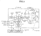
- the circuit construction of the first embodiment of the present invention will now be described with reference to Fig. 3.
- the camera unit 5 can be thought from the status of signals to be processed that it is constituted by an optical part and an electric part.
- the optical part is constituted by mirrors 22 for reflecting reflected light beam 21 in the sight 11 of field of the camera several times, a shading compensator 24 for performing shading compensation, filters, a converging or focusing lens 27 and a linear array CCD 29 for receiving image from the lens 27.
- the electric part is constituted by a CCD circuit 30 for performing photo-electric conversion, a CCD drive circuit 32 for generating CCD drive signal, a video signal processing circuit 38 for digitally converting electric signal from the CCD circuit 30 by amplification and normalization and performing compensation of each digital image, an image data transfer circuit 34 for performing parallel-to-serial conversion of video signal and outputting the resultant signal to an image recognition processor 35 in a recognition unit 7, a control circuit 37 for communicating with a parameter controller 37 in the recognition unit 7 by receiving signals from the photoelectric sensor 3, the area sensor 4 and the rotary encoder 9 and setting parameters in an auto-focusing module 31 and a video signal processing circuit 33.
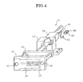
- a linear stepping motor 38 is secured to a securing member 42.
- the securing member 42 also has a role of causing escape of heat from the motor, and to this end it uses a good heat conductor metal.
- a CCD board securing member 43 is mounted on the end of the shaft of the linear stepping motor 38.
- a CCD board 44 which supports the linear array CCD 29, a shield plate 28 for partly shielding light therefrom and the CCD circuit 30, is mounted on the CCD board securing member 43 by CCD board securing screws 45.
- a beam blocking plate 41 for origin and edge detection is mounted on the motor shaft, and a photoelectric origin sensor 39 and photoelectric edge limit sensors 40 are disposed in relation to the beamblocking plate 41.
- Fig. 5 shows a power supply unit 13, which includes an alarm signal generating circuit 47 for detecting various alarm signals from lamp funs 46 and the like and outputting the detected signals to the camera unit 5, a power supply 48, an hour meter 49 for integrating and displaying time passed for maintenance purpose and a power supply circuit breaker 50.
- the recognition unit 7 is constituted by the image recognition processor 35, which performs an image recognition process on image data from the image data transfer circuit 34, and a parameter controller 36, which transfers various parameters at a certain timing of the photoelectric sensor 3 to the auto-focusing module 31 and the video signal processing circuit 33 according to the values of data from the area sensor 4.
- the illumination unit 6 shown in Fig. 1 has its illumination light beam optical axis angle 52 which, like the optical axis 51 of the camera, is set such that it makes an acute angle with respect to a direction perpendicular to the transport direction 8, while performing illumination at an angle slightly different from the optical axis angle 51 of the camera.
- the illumination unit 6 also performs illumination as uniformly and with as high illumination intensity as possible in the necessary scene object depth and field of view range of the camera.
- Fig. 7 shows illumination intensities in the field of view range of the camera at various height positions.
- the auxiliary reflector 20 has an effect of suppressing the maximum-to-minimum ratio from more than 4 times to less than two times, thus improving the uniformity.
- the mails 2 are transported on the transport conveyor 1 at a constant speed.
- Signal from the photoelectric sensor 3, which is of transmitting type and is disposed in front of the area sensor 4, is outputted as signal representing area sensor data take-out timing and imaging timing to the camera unit 5.
- the control circuit 37 in the camera unit 5 takes out area sensor data by using the pulse signal from the rotary encoder 9 and causing delay of the signal from the photoelectric sensor 3 to an extent corresponding to the distance between the photoelectric sensor 3 and the area sensor 4.
- the control circuit 37 detects the inter-mail interval from the signal of the photoelectric sensor 3.
- the data of the area sensor 4 is transferred via the control circuit 37 to the parameter controller 36.
- the parameter controller 36 presets gain compensation parameter and thinning-out parameter in LUT form in the video signal processing circuit 33 right before the start of imaging upon appearance of a mail in the field 11 of sight of the camera.
- gain compensation parameter 57 is preset in an analog gain amplifier 58, and level variations of video signal 56 due to brightness variations corresponding to the height of illumination are suppressed before analog-to-digital conversion.
- Illumination intensity variations corresponding by the reflectors 17 and the auxiliary reflector 20 to the height of illumination have been suppressed to extents as shown in Fig. 7. It is possible as well to suppress brightness variation by designing the reflectors in greater details. Doing so, however, is not practical from the standpoints of both cost and mass production. Accordingly, the variation suppression based on the reflector design is made only up to coarse adjustment to extents as shown in Fig. 7, and fine adjustment is made in the gain compensator.
- the timing of appearance of the mail in the field 11 of sight of the camera is varied according to the height of the mail, i.e., the area sensor data.
- the position of start of imaging is different by about 16 cm with a difference of height of 50 cm (50 cm x tan (10 degrees)).
- the imaging start timing delay is preliminarily calculated from the optical axis angle 51 of the camera and tabulated in the parameter controller 36, and delay parameter corresponding to the area sensor data is read out in the LUT and preset in the control circuit 37.
- the parameter controller 36 presets the step number of the linear stepping motor 38 in the auto-focusing module 31.
- the timing of this presetting has to take the operation time of the auto-focusing module 31 into considerations.
- the inter-mail interval of adjacent mails is longer than the positioning motion time (about 1880 msec. at the most) after the restoration to the origin, absolute positioning is made.
- the step number of the linear stepping motor 38 is set as the step number preset in the parameter controller 36.
- the presetting is made 180 msec. before the imaging, and at the same time the operation of restoration to the origin is started. After the restoration to the origin, positioning motion is caused by the automatically preset step number.
- the step number of the linear stepping motor 38 is set as the difference of the step number from the step number preset in the parameter controller 36 of the step number corresponding to the immediately preceding mail.
- the sign of the difference represents the direction of motion.
- the stepping motor is moved by the absolute value step number in the direction to cause the CCD to move toward the lens (i.e., scene object) in the negative difference case and to move away from the lens in the positive difference case.
- the presetting is made before the start of imaging by a time, which is a sum of a time proportional to the step number and an off-set of acceleration or deceleration, and at the same time the motion of that step number is started.
- the motion of the stepping motor is started during imaging of the present mail so as to be above to be in time for the imaging of the next mail.
- an experimentally obtained approximation plot 62 of measurement data 63 and a plot 61 which is obtained by adding off-set to a geo-optically theoretically obtained plot are substantially coincident.
- subsequent presetting is possible by merely adjusting the off-set.
- the offset adjustment may be made by setting a focus adjustment chart in the field 11 of sight of the camera at a height of 0 mm, fixing the CCD 29 in position by moving the same by the step number before the height of 0 mm and turning the lens focusing ring.
- the offset adjustment may be made without moving the lens but by causing automatic step-by-step movement of the CCD 29 while taking out image and resetting the step number at the sharpest image position as the value of this time at the height of 0 mm.
- the stepping motor is moved only for the above relative or absolute positioning.
- the mail height is varying, it is also possible to cause follow-up movement of the stepping motor for auto-focusing in relation to a height profile obtained in the area sensor.
- the stepping motor is moved step by step by the step number corresponding to the height profile by matching its follow-up movement speed with the transport speed.
- reflected light 21 from the surface of postal matter 2 is reflected a plurality of times by a plurality of mirrors 22 and then focused by the lens 27 on the CCD 29.
- the mirrors 22 should be large in size and elongate in the direction of the field 11 of sight of the camera, and those which have a high surface accuracy of ⁇ /4 and a thickness of 100 mm or above are used lest distortion should result at the mounting time.
- the use of a plurality of mirrors is adopted in order to provide as long optical path length in a limited space and suppress image magnification variations with height variation of mails 2 as much as possible.
- magnification variations as shown in Fig. 10 take place even with an optical path lengths of about 3.5 m. Accordingly, the variations are compensated for to 10 % or below even at a height of 1,000 mm as shown by plot 65 in Fig. 10 by making a thinning-out process in accordance with the height.
- the thinning-out is made by presetting thinning-out parameter 74 in an image compensation circuit 60 of the video signal processing circuit 33 substantially at the timing of presetting the gain compensation parameter 57.
- the movable mirror block 23 permits, when moved back and forth, changing the optical path length to an extent corresponding to double the movement, and it is thus particularly advantageous for optical path adjustment in a long optical path case as noted above.
- a shading corrector 24, a polarization filter 25 and an infrared-cut filter 26 are disposed in front of the lens 27.
- the shading corrector 24 is semi-circular, for instance, and serves to reduce the light intensity in a central part of the light beam to compensate for shading (i.e., brightness irregularities) due to the characteristics of the lens itself.
- the infrared-cut filter cuts infrared rays off near-infrared rays remaining in the illumination light beam, thus enhancing the contrast of letters or characters in ink reflectable by near-infrared rays such as ink of a ball pen.
- the polarization filter 25 suppresses right reflection light from a mail wrapped in a wrapping material readily giving rise to right reflection such as vinyl.
- a sharp-cut filter is provided for coarse balance adjustment by transmitting blue to green color components without any light intensity reduction and transmitting the sole red color components in reduced light intensity.
- the lens 27 is selectively adopted such as to take out a field of view of 512 mm in a magnification of 8.0 lines per mm as scan direction resolution.
- the CCD 29 converts the light beam signal focused by the lens 27 to electric signal.
- the CCD is used a versatile one with a pixel number more than the above pixel number.
- the exposure time is preset to be shorter than the full pixel data transfer time. In this case, for avoiding image quality deterioration due to overlap of the next exposure light during transfer of pixel data after the exposure, the light shield plate 28 is used to prohibit exposure to pixels other than those in actual use.
- video signal 56 outputted from the CCD circuit 30 subjected to gain compensation in the video signal processing circuit 33, and then analog-to-digital converted.
- the image compensation circuit 60 first detects the envelopes of the linear array CCD in the forward and reverse directions for gradation conversion and light dispersion compensation, and then performs a thinning-out process.
- Fig. 11 shows the circuit construction for this process
- the digital signal output of the A/D converter 69 is written in the output order of the linear array CCD in the original image memory 60, which has a capacity of holding a plurality of times. Then, image data for one line is subjected to a smoothing process 67, then the image data is read out in the direction of the output order of the CCD and also in the reverse direction for envelope detection process, and the resultant data are written in a forward and a reverse direction envelope memory 68 and 69.
- Figs. 12 (A) to 12 (B) illustrate forward direction envelope detection.
- light level comparison of a pixel under notice and the immediately preceding pixel in the CCD forward output direction in an image line signal 77 which has been read out from the original image memory 66 and subjected to the smoothing process 77, is made. If the light level of the pixel under notice is higher, the difference of a certain value from that value is made to be the value of present pixel. Otherwise, the light level of the immediately preceding pixel is made to be the value of the present pixel. Then, forward direction envelope signal follow-up signal 78 of one line is generated and written in the forward direction envelope memory 68.
- Figs. 12(C) and 12(D) reverse direction envelope detection.
- light level comparison of a pixel under notice and an immediately preceding pixel in the CCD output order direction in image line signal 77 which has been read out from the original image memory 66 and subjected to smoothing process . If the light level of the pixel under notice is higher, the difference of a certain value from that value is made to be the value of the present value. Otherwise, the light level of the preceding pixel is made to be the value of the present pixel. Then, reverse direction envelope follow-up signal 61 for one line is generated and written in the reverse direction envelope memory 69.
- Figs. 12(E) and 12(F) show envelope follow-up signals 82 obtained after the process. It will be seen that contrast of the envelope signals before and after the right reflection as shown in Figs. 12 (B) and 12 (D) with respect to the image line signal can be perfectly removed except for deviation for one line.
- envelope line follow-up signals 82 is fed as upper address to a ROM 71.
- the original image line signal which has been the basis of the envelope signal, is fed as lower signal from the original image memory 66.
- the presetting of the calculated envelope follow-up signals 82 to the white reference level as the paper surface level follow-up value it is possible to compensate for illumination irregularities and also irregularities due to lens shading and the like in one line scan while holding optimum gradation, as well as absorbing time variations from the illumination light source turn-on time and long-term deterioration variations, thus obtaining uniformly bright images at all times.
- the illumination non-uniformity correction data 73 as the above calculation result is calculated in the parameter controller 36 in the recognition unit 7, and is written via the control circuit 36 at the time of adjustment for shipment or like timing.
- the output of the ROM 71 having been gradation converted and illumination non-uniformity correction, is subjected to a thinning-out process 72 according to the area sensor value, and is then fed to the image data transfer circuit 34.
- the image data transfer circuit 34 transfers image data as image via optical fiber or in the form of LVDS signal to the image recognition processor 35 in the image recognition unit 7.
- image recognition process such processes as letter or character recognition process for recognizing postal number, address, ISBN code number of book, etc. and indetia or like detection process may be done.
- ISBN code number there are many colorful ones, and in this case recognition by color imaging is advantageous.
- the timing of imaging is not varied according to the value of the area sensor value. Also, unlike the case of Fig. 6, this embodiment is free from a case that imaging becomes impossible due to height relation of mail to the next one.
- this embodiment is free from a case that imaging becomes impossible due to height relation of mail to the next one.
- doubling of the illumination light intensity the scene object can be illuminated with increased illumination intensity. This leads to depth improvement of the camera with freedom from mechanical auto-focusing by operating the lens stop, and permits improving the image focus with respect to irregularities of the scene object in the scan direction. Furthermore, with reduced shutter time it is possible to take out images of improved resolution.
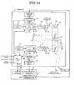
- camera unit 5 is provided with both high resolution monochromatic imaging and low resolution color imaging functions.
- Fig. 14 is a block diagram showing the construction of the camera unit 5.
- a light beam 101 for monochromatic imaging and a light beam 102 for color imaging are reflected by mirror 22 while they are held parallel and spaced apart a predetermined distance.
- the construction of the optical paths of the monochromatic and color light beams up to the CCD are substantially the same in construction as in the above embodiments except for the provision of a sharp-cut color filter 103.
- the two optical paths are basically the same in the subsequent stage as well.
- white level compensation is further added in a monochromatic illumination non-uniformity correction.
- the difference of resolution leads to a difference of the step number of the stepping motor, i.e., a difference of a delay parameter for presetting the image take-out timing from the difference of the position under notice.
- Color low resolution images are transferred to an image recognition region detector 104 in recognition unit 4 to be used for finding out a region, in which image recognition is actually caused, in image taken out as high resolution monochromatic image.
- image recognition region detector 104 in recognition unit 4 to be used for finding out a region, in which image recognition is actually caused, in image taken out as high resolution monochromatic image.
- subject areas for image recognition are always written in blue frames or provided with red heart marks, they are detected as low resolution color images and added to an area including a certain margin from the detected position for image recognition in high resolution monochromatic images.
- optical axis angle 5 of the camera is preset to 45 degrees for imaging not only the top surface of the scene object but also the rear surface (or front surface) thereof.
- camera unit 5 is installed as shown in Fig. 1, with the optical axis 10 of the camera directed downward from an obliquely rearward position in the transport direction, after imaging the top surface as,in the first embodiment, the rear surface is imaged with auto-focusing follow-up according to the height up to a height of 0 mm.
- the front surface is first imaged with auto-focusing follow-up from a height of 0 mm up to the height of mail, and then the top surface is imaged as in the first embodiment.
- a side surface of the mail is first imaged with positioning of the auto-focusing in direction 112 according to the output of an area sensor 111 for position detection. Then, the rear surface of the mail is imaged with auto-focusing follow-up in a direction 113.
- the area sensor 111 for position detection like the photoelectric sensor 3 and the area sensor 4 for height detection, is vertically disposed forwardly of the field 10 of sight of the camera in the transport conveyor at a conveyor seam.
- the front surface is first imaged with auto-focusing follow-up, and then a side surface is imaged with fixed auto-focusing.
- a fifth embodiment of the present invention will now be described in detail with reference to the drawings.
- a plurality of camera units as that in the first embodiment are used and disposed differently in the fashion as in the fourth embodiment for imaging mails in a total of six different directions.
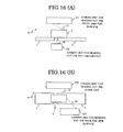
- Fig. 16(A) is a side view showing the camera unit disposition in this embodiment.
- illumination unit paired with each camera unit photo-electric sensor 3, area sensor 4 for height detection, an area sensor 111 for position detection, are not shown.
- a camera unit 121 for reading out the front and top surfaces of mails is disposed such that the optical axis 16 of the camera is directed downward from an obliquely forward position in the transport direction.
- a camera unit 122 for reading out the bottom surface of the camera is disposed such that the optical axis of the camera extends upward from a conveyor seam.
- Fig. 16 (B) is a bottom view showing the camera unit disposition in this embodiment.
- a camera unit 124 for reading out the rear and side surfaces of mails is disposed such that the optical axis of the camera 10 is directed forward from an obliquely rearward position in the transport direction.
- a camera unit 122 for reading out the other side surface of mails is disposed on the opposite side.
Landscapes
- Engineering & Computer Science (AREA)
- Physics & Mathematics (AREA)
- General Physics & Mathematics (AREA)
- Multimedia (AREA)
- Theoretical Computer Science (AREA)
- Image Input (AREA)
- Facsimile Scanning Arrangements (AREA)
- Studio Devices (AREA)
- Automatic Focus Adjustment (AREA)
- Sorting Of Articles (AREA)
- Focusing (AREA)
Applications Claiming Priority (2)
| Application Number | Priority Date | Filing Date | Title |
|---|---|---|---|
| JP2002063655 | 2002-03-08 | ||
| JP2002063655A JP4251312B2 (ja) | 2002-03-08 | 2002-03-08 | 画像入力装置 |
Publications (3)
| Publication Number | Publication Date |
|---|---|
| EP1343110A2 true EP1343110A2 (de) | 2003-09-10 |
| EP1343110A3 EP1343110A3 (de) | 2005-03-30 |
| EP1343110B1 EP1343110B1 (de) | 2010-05-26 |
Family
ID=27751255
Family Applications (1)
| Application Number | Title | Priority Date | Filing Date |
|---|---|---|---|
| EP03004975A Expired - Lifetime EP1343110B1 (de) | 2002-03-08 | 2003-03-10 | Bildeingabegerät |
Country Status (4)
| Country | Link |
|---|---|
| US (1) | US7778443B2 (de) |
| EP (1) | EP1343110B1 (de) |
| JP (1) | JP4251312B2 (de) |
| DE (1) | DE60332684D1 (de) |
Cited By (3)
| Publication number | Priority date | Publication date | Assignee | Title |
|---|---|---|---|---|
| EP1645838A1 (de) * | 2004-10-11 | 2006-04-12 | Sick AG | Vorrichtung und Verfahren zur Überwachung von bewegten Objekten |
| EP1845336A1 (de) * | 2006-04-11 | 2007-10-17 | Sick Ag | Verfahren zur optischen Erfassung von bewegten Objekten und Vorrichtung |
| US7721964B2 (en) | 2004-10-11 | 2010-05-25 | Sick Ag | Apparatus and method for monitoring moved objects |
Families Citing this family (17)
| Publication number | Priority date | Publication date | Assignee | Title |
|---|---|---|---|---|
| JP2005216169A (ja) * | 2004-01-30 | 2005-08-11 | Toshiba Tec Corp | 画像読取装置 |
| JP5302511B2 (ja) * | 2007-03-28 | 2013-10-02 | 三菱重工業株式会社 | 2波長赤外線画像処理装置 |
| US20080257795A1 (en) * | 2007-04-17 | 2008-10-23 | Eriez Manufacturing Co. | Multiple Zone and Multiple Materials Sorting |
| JP4906609B2 (ja) | 2007-06-29 | 2012-03-28 | キヤノン株式会社 | 撮像装置および方法 |
| CH699243A2 (de) * | 2008-07-25 | 2010-01-29 | Ferag Ag | Optisches Kontrollverfahren zur Erkennung von Druckereierzeugnissen bei der Druckweiterverarbeitung. |
| US20120182588A1 (en) * | 2011-01-14 | 2012-07-19 | Mampe John J | Distributed image acquisition for postal processing |
| USD668656S1 (en) * | 2011-01-24 | 2012-10-09 | Datalogic ADC, Inc. | Tunnel scanner |
| US9167348B1 (en) | 2012-03-08 | 2015-10-20 | shenYon, Inc. | Wireless waterproof headphone system |
| EP2763105B1 (de) * | 2013-01-31 | 2018-08-22 | Neopost Technologies | Bilderfassungssystem zur Verarbeitung und Verfolgung von Postsendungen |
| US10600213B2 (en) * | 2016-02-27 | 2020-03-24 | Focal Sharp, Inc. | Method and apparatus for color-preserving spectrum reshape |
| US9805257B1 (en) * | 2016-09-07 | 2017-10-31 | Datamax-O'neil Corporation | Printer method and apparatus |
| CN106269532B (zh) * | 2016-09-14 | 2018-05-25 | 山东大学 | 自动化物流分拣系统 |
| TWI690692B (zh) * | 2018-08-24 | 2020-04-11 | 菱光科技股份有限公司 | 外部觸發之線性相機檢測系統及其影像曝光處理方法 |
| CN110721916B (zh) * | 2019-10-18 | 2021-05-07 | 兴盛社区网络服务股份有限公司 | 一种物流分拣系统及其分拣方法 |
| CN113218900A (zh) * | 2021-05-07 | 2021-08-06 | 江苏凤凰通达印刷有限公司 | 一种书籍印刷品质检测系统 |
| EP4270917B1 (de) | 2022-04-29 | 2024-04-24 | Sick Ag | Kamera und verfahren zur erfassung eines objekts |
| CN116161396B (zh) * | 2023-02-15 | 2025-08-22 | 凌云光技术股份有限公司 | 基于3d视觉的行李分拣系统 |
Family Cites Families (37)
| Publication number | Priority date | Publication date | Assignee | Title |
|---|---|---|---|---|
| JPS52143824A (en) | 1976-05-26 | 1977-11-30 | Hitachi Ltd | Search device for micro=fiche |
| DE2914517A1 (de) * | 1979-04-10 | 1980-10-23 | Siemens Ag | Halbleiterschaltung mit taktgesteuerten ladungsverschiebungsanlagen |
| US4578749A (en) * | 1982-06-23 | 1986-03-25 | Kabushiki Kaisha Toyota Chuo Kenkyusho | Method for measuring driving amount of motor and apparatus therefor |
| US4553193A (en) * | 1983-02-01 | 1985-11-12 | Gamma One Conversions, Inc. | Scanning light system |
| US4575248A (en) * | 1984-06-18 | 1986-03-11 | Itek Corporation | Wavefront sensor employing novel D.C. shearing interferometer |
| US4734612A (en) * | 1985-07-15 | 1988-03-29 | Kabushiki Kaisha Toshiba | High pressure metal vapor discharge lamp |
| US4755044A (en) * | 1986-01-06 | 1988-07-05 | Massachusetts Institute Of Technology | Remote ophthalmoscope and fundus photography unit |
| JPS62254001A (ja) * | 1986-04-28 | 1987-11-05 | Hitachi Ltd | 高精度測長機 |
| JPH0713832B2 (ja) | 1987-02-02 | 1995-02-15 | 松下電器産業株式会社 | 画像情報入力装置 |
| US4725879A (en) * | 1987-03-27 | 1988-02-16 | Honeywell Inc. | Chroma responsive inspection apparatus selectively producing analog voltage levels based on the luminance, the phase of the chrominance subcarrier, or the amplitude of the chrominance subcarrier |
| US4972494A (en) * | 1988-02-26 | 1990-11-20 | R. J. Reynolds Tobacco Company | Package inspection system |
| JPH02171883A (ja) | 1988-12-23 | 1990-07-03 | Nec Corp | 光学文字読取装置 |
| JPH02254001A (ja) | 1989-03-28 | 1990-10-12 | Kanai Hiroyuki | 自動車用車輪及びその製造方法 |
| DE69127112T2 (de) * | 1990-02-28 | 1998-03-05 | Sanyo Electric Co | Automatisches Fokussierungsgerät zur automatischen Fokusanpassung in Abhängigkeit von Videosignalen |
| JPH04331562A (ja) * | 1990-07-31 | 1992-11-19 | Xerox Corp | 文書複写機 |
| US6736321B2 (en) * | 1995-12-18 | 2004-05-18 | Metrologic Instruments, Inc. | Planar laser illumination and imaging (PLIIM) system employing wavefront control methods for reducing the power of speckle-pattern noise digital images acquired by said system |
| JP3160906B2 (ja) | 1990-11-29 | 2001-04-25 | 株式会社ニコン | フィルム画像読取り装置 |
| US5255088A (en) * | 1992-01-29 | 1993-10-19 | Arc Machines, Inc. | System and process for video monitoring a welding operation |
| US5461417A (en) * | 1993-02-16 | 1995-10-24 | Northeast Robotics, Inc. | Continuous diffuse illumination method and apparatus |
| IL107265A0 (en) | 1993-10-12 | 1994-01-25 | Galai Lab Ltd | Parcel sorting system |
| BR9408547A (pt) | 1994-03-07 | 1997-08-19 | Ibm | Aparelho e método para extrair informaçÕes de encaminhamento a partir de embrulho para uso subsequente na triagem dos embrulhos que compreendem aparelho e método de processamento de imagens para localizar rótulos em imagens de embrulho |
| EP0679021B1 (de) * | 1994-04-19 | 2010-12-15 | Eastman Kodak Company | Kamera mit automatischer Belichtungssteuerung unter Verwendung von CCD-Sensor mit verstellbarem Belichtungsindex |
| DE19535038A1 (de) * | 1994-09-22 | 1996-03-28 | Nec Corp | Vorrichtung und Verfahren zum Erfassen einer Aufkleber/Fenster-Position |
| US5699161A (en) * | 1995-07-26 | 1997-12-16 | Psc, Inc. | Method and apparatus for measuring dimensions of objects on a conveyor |
| DE19532842C1 (de) | 1995-09-05 | 1996-12-19 | Ibm | Bildaufnahmesystem |
| FR2746330B1 (fr) | 1996-03-22 | 1998-04-17 | Alcatel Postal Automation Syst | Systeme d'acquisition d'images pour le tri de paquets |
| DE19639854A1 (de) * | 1996-09-27 | 1998-06-10 | Vitronic Dr Ing Stein Bildvera | Verfahren und Vorrichtung zur Erfassung von auf potentiell großflächigen Gegenständen aufgebrachten, optisch erfaßbaren Informationen |
| US6115147A (en) * | 1996-10-01 | 2000-09-05 | Fuji Photo Film Co., Ltd. | Image reading apparatus |
| ES2271447T3 (es) | 1997-01-23 | 2007-04-16 | United Parcel Service Of America, Inc. | Sistema lector de signos guiado de forma optica. |
| US6040677A (en) * | 1997-02-10 | 2000-03-21 | Asahi Kogaku Kogyo Kabushiki Kaisha | Apparatus for driving stepper motor of camera |
| US6704501B1 (en) * | 1997-02-18 | 2004-03-09 | Canon Kabushiki Kaisha | Image blur prevention apparatus |
| US6421451B2 (en) * | 1997-09-16 | 2002-07-16 | Kabushiki Kaisha Toshiba | Step difference detection apparatus and processing apparatus using the same |
| US6484066B1 (en) * | 1999-10-29 | 2002-11-19 | Lockheed Martin Corporation | Image life tunnel scanner inspection system using extended depth of field technology |
| JP2001174695A (ja) | 1999-12-21 | 2001-06-29 | Nec Corp | オートフォーカス装置及びその方法 |
| JP3606151B2 (ja) * | 2000-03-02 | 2005-01-05 | 日本電気株式会社 | 画像入力装置 |
| WO2002025345A2 (en) * | 2000-09-22 | 2002-03-28 | Applied Science Fiction | Lens focusing device, system and method for use with multiple light wavelengths |
| US7053953B2 (en) * | 2001-12-21 | 2006-05-30 | Eastman Kodak Company | Method and camera system for blurring portions of a verification image to show out of focus areas in a captured archival image |
-
2002
- 2002-03-08 JP JP2002063655A patent/JP4251312B2/ja not_active Expired - Fee Related
-
2003
- 2003-03-07 US US10/384,886 patent/US7778443B2/en not_active Expired - Fee Related
- 2003-03-10 EP EP03004975A patent/EP1343110B1/de not_active Expired - Lifetime
- 2003-03-10 DE DE60332684T patent/DE60332684D1/de not_active Expired - Lifetime
Cited By (3)
| Publication number | Priority date | Publication date | Assignee | Title |
|---|---|---|---|---|
| EP1645838A1 (de) * | 2004-10-11 | 2006-04-12 | Sick AG | Vorrichtung und Verfahren zur Überwachung von bewegten Objekten |
| US7721964B2 (en) | 2004-10-11 | 2010-05-25 | Sick Ag | Apparatus and method for monitoring moved objects |
| EP1845336A1 (de) * | 2006-04-11 | 2007-10-17 | Sick Ag | Verfahren zur optischen Erfassung von bewegten Objekten und Vorrichtung |
Also Published As
| Publication number | Publication date |
|---|---|
| US20030169364A1 (en) | 2003-09-11 |
| JP4251312B2 (ja) | 2009-04-08 |
| US7778443B2 (en) | 2010-08-17 |
| EP1343110A3 (de) | 2005-03-30 |
| EP1343110B1 (de) | 2010-05-26 |
| DE60332684D1 (de) | 2010-07-08 |
| JP2003262785A (ja) | 2003-09-19 |
Similar Documents
| Publication | Publication Date | Title |
|---|---|---|
| EP1343110B1 (de) | Bildeingabegerät | |
| EP0439357A2 (de) | Verfahren und Vorrichtung zur Ausstattung eines Dokumentenlesers mit Sensorkompensation | |
| US5969829A (en) | Image reader that stores sets of luminance correction data corresponding to document a surface height | |
| CN102572196A (zh) | 影像传感器单元以及图像读取装置 | |
| US20030067613A1 (en) | Displacement sensor | |
| EP1501278A3 (de) | Bildverarbeitungsvorrichtung zur Lösung des Staubsproblems | |
| US4547813A (en) | Apparatus for controlling light distribution in line scan optical imaging systems | |
| EP0106672A1 (de) | Vorrichtung zur Abtastung von Informationen von bewegten Objekten, welche eine automatische Lichtregelung verwendet | |
| US5117295A (en) | Structure for and method of scanning with multiplexed light sensor arrays | |
| US6798896B2 (en) | Image input apparatus | |
| US5025313A (en) | System for minimizing optical distortions and chromatic aberrations in a linear color scanner | |
| US6493114B1 (en) | Adaptive timing control of light integration process in one-dimensional CMOS image sensors | |
| US6201619B1 (en) | Autofocus process and system with fast multi-region sampling | |
| US6566646B1 (en) | Image input apparatus for reading conveyed items using air flow cooling of illumination windows | |
| US20030234963A1 (en) | Compact scanner and scanning method | |
| JP4807402B2 (ja) | 画像入力装置 | |
| JP5423094B2 (ja) | 画像入力装置、画像入力方法、及び、紙葉類処理装置 | |
| JP2023164304A (ja) | カメラ及び物体検出方法 | |
| JPH1049654A (ja) | 画像取込装置の信号補正方法 | |
| JPH09200440A (ja) | 画像読取り装置 | |
| US6301024B1 (en) | Image reading device | |
| JP5118083B2 (ja) | 書籍コピー機のためのデュアルミラー照明システム | |
| KR100268340B1 (ko) | 셔틀방식 스캐너의 쉐이딩 보정방법 | |
| JP2998971B2 (ja) | 画像読取装置 | |
| KR100277732B1 (ko) | 셔틀방식 스캐너의 쉐이딩 보정방법 |
Legal Events
| Date | Code | Title | Description |
|---|---|---|---|
| PUAI | Public reference made under article 153(3) epc to a published international application that has entered the european phase |
Free format text: ORIGINAL CODE: 0009012 |
|
| AK | Designated contracting states |
Kind code of ref document: A2 Designated state(s): AT BE BG CH CY CZ DE DK EE ES FI FR GB GR HU IE IT LI LU MC NL PT SE SI SK TR |
|
| AX | Request for extension of the european patent |
Extension state: AL LT LV MK RO |
|
| PUAL | Search report despatched |
Free format text: ORIGINAL CODE: 0009013 |
|
| AK | Designated contracting states |
Kind code of ref document: A3 Designated state(s): AT BE BG CH CY CZ DE DK EE ES FI FR GB GR HU IE IT LI LU MC NL PT SE SI SK TR |
|
| AX | Request for extension of the european patent |
Extension state: AL LT LV MK RO |
|
| RIC1 | Information provided on ipc code assigned before grant |
Ipc: 7B 07C 3/14 B Ipc: 7G 06K 9/20 A |
|
| 17P | Request for examination filed |
Effective date: 20050218 |
|
| AKX | Designation fees paid |
Designated state(s): DE FR |
|
| 17Q | First examination report despatched |
Effective date: 20070308 |
|
| GRAP | Despatch of communication of intention to grant a patent |
Free format text: ORIGINAL CODE: EPIDOSNIGR1 |
|
| GRAS | Grant fee paid |
Free format text: ORIGINAL CODE: EPIDOSNIGR3 |
|
| RIN1 | Information on inventor provided before grant (corrected) |
Inventor name: KATO, HISATO Inventor name: SINGU, SATOSHI Inventor name: IWAKAWA, MASATO Inventor name: WATANABE, MITSURU |
|
| GRAA | (expected) grant |
Free format text: ORIGINAL CODE: 0009210 |
|
| AK | Designated contracting states |
Kind code of ref document: B1 Designated state(s): DE FR |
|
| REF | Corresponds to: |
Ref document number: 60332684 Country of ref document: DE Date of ref document: 20100708 Kind code of ref document: P |
|
| PLBE | No opposition filed within time limit |
Free format text: ORIGINAL CODE: 0009261 |
|
| STAA | Information on the status of an ep patent application or granted ep patent |
Free format text: STATUS: NO OPPOSITION FILED WITHIN TIME LIMIT |
|
| 26N | No opposition filed |
Effective date: 20110301 |
|
| PGFP | Annual fee paid to national office [announced via postgrant information from national office to epo] |
Ref country code: FR Payment date: 20110317 Year of fee payment: 9 |
|
| REG | Reference to a national code |
Ref country code: DE Ref legal event code: R097 Ref document number: 60332684 Country of ref document: DE Effective date: 20110228 |
|
| PGFP | Annual fee paid to national office [announced via postgrant information from national office to epo] |
Ref country code: DE Payment date: 20110302 Year of fee payment: 9 |
|
| REG | Reference to a national code |
Ref country code: FR Ref legal event code: ST Effective date: 20121130 |
|
| REG | Reference to a national code |
Ref country code: DE Ref legal event code: R119 Ref document number: 60332684 Country of ref document: DE Effective date: 20121002 |
|
| PG25 | Lapsed in a contracting state [announced via postgrant information from national office to epo] |
Ref country code: FR Free format text: LAPSE BECAUSE OF NON-PAYMENT OF DUE FEES Effective date: 20120402 |
|
| PG25 | Lapsed in a contracting state [announced via postgrant information from national office to epo] |
Ref country code: DE Free format text: LAPSE BECAUSE OF NON-PAYMENT OF DUE FEES Effective date: 20121002 |