EP1343165A1 - Dispositif de reproduction et d'enregistrement de type a disque - Google Patents
Dispositif de reproduction et d'enregistrement de type a disque Download PDFInfo
- Publication number
- EP1343165A1 EP1343165A1 EP02741370A EP02741370A EP1343165A1 EP 1343165 A1 EP1343165 A1 EP 1343165A1 EP 02741370 A EP02741370 A EP 02741370A EP 02741370 A EP02741370 A EP 02741370A EP 1343165 A1 EP1343165 A1 EP 1343165A1
- Authority
- EP
- European Patent Office
- Prior art keywords
- disk
- disk recording
- reproduction apparatus
- recording medium
- pickups
- Prior art date
- Legal status (The legal status is an assumption and is not a legal conclusion. Google has not performed a legal analysis and makes no representation as to the accuracy of the status listed.)
- Granted
Links
Images








Classifications
-
- G—PHYSICS
- G11—INFORMATION STORAGE
- G11B—INFORMATION STORAGE BASED ON RELATIVE MOVEMENT BETWEEN RECORD CARRIER AND TRANSDUCER
- G11B17/00—Guiding record carriers not specifically of filamentary or web form, or of supports therefor
- G11B17/02—Details
- G11B17/04—Feeding or guiding single record carrier to or from transducer unit
- G11B17/05—Feeding or guiding single record carrier to or from transducer unit specially adapted for discs not contained within cartridges
- G11B17/053—Indirect insertion, i.e. with external loading means
- G11B17/056—Indirect insertion, i.e. with external loading means with sliding loading means
- G11B17/0565—Indirect insertion, i.e. with external loading means with sliding loading means adapted for discs of different sizes
-
- G—PHYSICS
- G11—INFORMATION STORAGE
- G11B—INFORMATION STORAGE BASED ON RELATIVE MOVEMENT BETWEEN RECORD CARRIER AND TRANSDUCER
- G11B17/00—Guiding record carriers not specifically of filamentary or web form, or of supports therefor
- G11B17/02—Details
- G11B17/022—Positioning or locking of single discs
- G11B17/028—Positioning or locking of single discs of discs rotating during transducing operation
-
- G—PHYSICS
- G11—INFORMATION STORAGE
- G11B—INFORMATION STORAGE BASED ON RELATIVE MOVEMENT BETWEEN RECORD CARRIER AND TRANSDUCER
- G11B17/00—Guiding record carriers not specifically of filamentary or web form, or of supports therefor
- G11B17/02—Details
- G11B17/022—Positioning or locking of single discs
- G11B17/028—Positioning or locking of single discs of discs rotating during transducing operation
- G11B17/0284—Positioning or locking of single discs of discs rotating during transducing operation by clampers
- G11B17/0286—Positioning or locking of single discs of discs rotating during transducing operation by clampers mounted on a pivotal lever
-
- G—PHYSICS
- G11—INFORMATION STORAGE
- G11B—INFORMATION STORAGE BASED ON RELATIVE MOVEMENT BETWEEN RECORD CARRIER AND TRANSDUCER
- G11B17/00—Guiding record carriers not specifically of filamentary or web form, or of supports therefor
- G11B17/02—Details
- G11B17/04—Feeding or guiding single record carrier to or from transducer unit
- G11B17/057—Feeding or guiding single record carrier to or from transducer unit specially adapted for handling both discs contained within cartridges and discs not contained within cartridges
-
- G—PHYSICS
- G11—INFORMATION STORAGE
- G11B—INFORMATION STORAGE BASED ON RELATIVE MOVEMENT BETWEEN RECORD CARRIER AND TRANSDUCER
- G11B7/00—Recording or reproducing by optical means, e.g. recording using a thermal beam of optical radiation by modifying optical properties or the physical structure, reproducing using an optical beam at lower power by sensing optical properties; Record carriers therefor
- G11B7/002—Recording, reproducing or erasing systems characterised by the shape or form of the carrier
- G11B7/0037—Recording, reproducing or erasing systems characterised by the shape or form of the carrier with discs
-
- G—PHYSICS
- G11—INFORMATION STORAGE
- G11B—INFORMATION STORAGE BASED ON RELATIVE MOVEMENT BETWEEN RECORD CARRIER AND TRANSDUCER
- G11B7/00—Recording or reproducing by optical means, e.g. recording using a thermal beam of optical radiation by modifying optical properties or the physical structure, reproducing using an optical beam at lower power by sensing optical properties; Record carriers therefor
- G11B7/08—Disposition or mounting of heads or light sources relatively to record carriers
-
- G—PHYSICS
- G11—INFORMATION STORAGE
- G11B—INFORMATION STORAGE BASED ON RELATIVE MOVEMENT BETWEEN RECORD CARRIER AND TRANSDUCER
- G11B7/00—Recording or reproducing by optical means, e.g. recording using a thermal beam of optical radiation by modifying optical properties or the physical structure, reproducing using an optical beam at lower power by sensing optical properties; Record carriers therefor
- G11B7/08—Disposition or mounting of heads or light sources relatively to record carriers
- G11B7/085—Disposition or mounting of heads or light sources relatively to record carriers with provision for moving the light beam into, or out of, its operative position or across tracks, otherwise than during the transducing operation, e.g. for adjustment or preliminary positioning or track change or selection
- G11B7/0857—Arrangements for mechanically moving the whole head
- G11B7/08582—Sled-type positioners
-
- G—PHYSICS
- G11—INFORMATION STORAGE
- G11B—INFORMATION STORAGE BASED ON RELATIVE MOVEMENT BETWEEN RECORD CARRIER AND TRANSDUCER
- G11B7/00—Recording or reproducing by optical means, e.g. recording using a thermal beam of optical radiation by modifying optical properties or the physical structure, reproducing using an optical beam at lower power by sensing optical properties; Record carriers therefor
- G11B7/12—Heads, e.g. forming of the optical beam spot or modulation of the optical beam
-
- G—PHYSICS
- G11—INFORMATION STORAGE
- G11B—INFORMATION STORAGE BASED ON RELATIVE MOVEMENT BETWEEN RECORD CARRIER AND TRANSDUCER
- G11B11/00—Recording on or reproducing from the same record carrier wherein for these two operations the methods are covered by different main groups of groups G11B3/00 - G11B7/00 or by different subgroups of group G11B9/00; Record carriers therefor
- G11B11/10—Recording on or reproducing from the same record carrier wherein for these two operations the methods are covered by different main groups of groups G11B3/00 - G11B7/00 or by different subgroups of group G11B9/00; Record carriers therefor using recording by magnetic means or other means for magnetisation or demagnetisation of a record carrier, e.g. light induced spin magnetisation; Demagnetisation by thermal or stress means in the presence or not of an orienting magnetic field
- G11B11/105—Recording on or reproducing from the same record carrier wherein for these two operations the methods are covered by different main groups of groups G11B3/00 - G11B7/00 or by different subgroups of group G11B9/00; Record carriers therefor using recording by magnetic means or other means for magnetisation or demagnetisation of a record carrier, e.g. light induced spin magnetisation; Demagnetisation by thermal or stress means in the presence or not of an orienting magnetic field using a beam of light or a magnetic field for recording by change of magnetisation and a beam of light for reproducing, i.e. magneto-optical, e.g. light-induced thermomagnetic recording, spin magnetisation recording, Kerr or Faraday effect reproducing
- G11B11/10595—Control of operating function
- G11B11/10597—Adaptations for transducing various formats on the same or different carriers
-
- G—PHYSICS
- G11—INFORMATION STORAGE
- G11B—INFORMATION STORAGE BASED ON RELATIVE MOVEMENT BETWEEN RECORD CARRIER AND TRANSDUCER
- G11B7/00—Recording or reproducing by optical means, e.g. recording using a thermal beam of optical radiation by modifying optical properties or the physical structure, reproducing using an optical beam at lower power by sensing optical properties; Record carriers therefor
- G11B2007/0003—Recording, reproducing or erasing systems characterised by the structure or type of the carrier
- G11B2007/0006—Recording, reproducing or erasing systems characterised by the structure or type of the carrier adapted for scanning different types of carrier, e.g. CD & DVD
-
- G—PHYSICS
- G11—INFORMATION STORAGE
- G11B—INFORMATION STORAGE BASED ON RELATIVE MOVEMENT BETWEEN RECORD CARRIER AND TRANSDUCER
- G11B7/00—Recording or reproducing by optical means, e.g. recording using a thermal beam of optical radiation by modifying optical properties or the physical structure, reproducing using an optical beam at lower power by sensing optical properties; Record carriers therefor
Definitions
- the present invention relates to a disk recording and reproduction apparatus and relates in particular to a disk recording and reproduction apparatus for recording and/or reproduction by using a pickup while rotating a disk recording medium.
- Disk recording and reproduction devices are widely used to perform recording or reproduction by utilizing an optical pickup while rotating a disk recording medium.
- an optical disk constituting the disk recording medium is accessed by an optical pickup by rotating the optical disk on a turntable and moving the optical pickup along the radius direction of the optical disk, and the specified recording or reproduction is performed.
- the laser light wavelength of the optical pickup varies according to the optical disk format.
- laser light of 780 nm (nanometers) wavelength is used.
- a DVD uses laser light of 650 nm wavelength.
- a so-called DVR capable of writing in a high density recording format utilizes laser light of 405 nm wavelength.
- optical pickup capable of emitting laser light at wavelengths suitable for all formats allows compatible use of all the above mentioned optical disk types by a single optical pickup.
- Two types of optical disks are used.
- One type is a bare disk not utilizing a cartridge.
- the other type is an optical disk stored inside a cartridge.
- the bare disk must be placed on a turntable and clamped in place by a clamping means.
- cartridge type optical disks usually have a clamping means inside the cartridge and do not require a clamping means in the recording and reproduction apparatus itself.
- a disk recording and reproduction apparatus configured to use compatibly both cartridge type optical disks and bare disks therefore had the problem that a means was required to retract a clamping mechanism used especially when a cartridge type optical disk was inserted.
- the present invention therefore has the object of providing a disk recording and reproduction apparatus capable of using multiple disk recording media that were impossible to be recorded or reproduced by a single pickup.
- a further object is to provide a disk recording and reproduction apparatus capable of retracting the clamping mechanism during loading of a cartridge type disk recording medium when a cartridge type disk recording medium or a bare disk type recording medium is selectively installed.
- One aspect of the present invention resides in a disk recording and reproduction apparatus for performing recording and/or reproduction with a pickup while rotating a disk recording medium, wherein the disk recording and reproduction apparatus is comprised of a common rotating drive means for driving multiple types of disk recording media of different formats, and multiple pickups respectively installed for the multiple types of disk recording media of different formats.
- the multiple pickups each have a drive means and when one pickup is accessing the recording medium with the corresponding format, the other pickups may be retracted to the outer circumferential side of the recording medium.
- multiple pickups may have their respective drive means, and when one pickup is accessing the recording medium with the corresponding format, the other pickups may be retracted to the outer side of the light projection area.
- the invention may also contain two types of pickups, and these two types of pickups may be installed approximately 180 degrees apart in a circumferential direction versus the center of rotation of the disk recording and reproduction apparatus. Pickups for formats susceptible to dust may be installed on the inner side of the case.
- the multiple pickups may also be capable of separate operating system alignment.
- a disk recording and reproduction apparatus for performing recording and/or reproduction with an optical pickup while rotating a disk recording medium
- said recording and reproduction apparatus comprises an installation means to selectively install a cartridge type disk recording medium and bare disk type recording medium, and a clamping means to clamp the bare disk type recording medium, and a drive means to move the clamping means to a non-operating position when the cartridge type disk recording means has been installed.
- the driving force of the installation means may be utilized to allow the cartridge to move the clamping means to a non-operating position.
- the resilient recovery force of the elastic member may be utilized to return the clamping means to the operating position.
- the clamping means may contain a movable retractor, and at the final stroke of the installation means to eject the cartridge, the retractor may be pulled out of the clamping means.
- the installation means may contain an engaging means having a limiter function and the retractor is pulled from the clamping means by the engaging means.
- a disk recording and reproduction apparatus capable of compatible use of two different formats for a DVR at a laser light wavelength of 405 nm and a DVD at a laser light wavelength of 650 nm uses two separate optical pickups installed corresponding to each of the above two formats. Furthermore, a single turntable for rotating all types of optical disks is installed and the above two optical pickups are installed facing each other at 180 degrees apart along the circumferential direction versus the turntable rotating the disk. The optical systems of each optical pickup are capable of separate alignment. Optical pickups having formats easily susceptible to dust may be installed toward the rear of the case to avoid errors caused by dust that otherwise might occur when inserting an optical disk into or ejecting it from this apparatus.
- the above structure of the present intention will take up less space in view of structures for using optical disks of multiple formats by a single apparatus. Also, when two optical disk pickups are installed along with the turntable onto a mono-strength base chassis, no overall movement mechanism is required for moving these components so dimensions are highly stable once assembled and adjusted.
- Another aspect of the present invention along with having separate optical pickups for multiple types of optical disks of different formats, is provided with an apparatus to drive the multiple types of optical disks on a common turntable.
- at least the objective lens unit of the other optical pickup is moved to the outer circumferential side of the optical disk or more preferably to the outer side of the light projection area. This is because the position of the objective lens unit is more protrudent than the other optical pickup, namely it is in the nearest position for the optical disk.
- An apparatus configured this way for using optical disks of mutually different formats prevents interference from occurring between the optical disk and multiple types of optical pickups and allows using a common turntable for driving various types of optical disks, so that less component space is required, fewer components are needed, and the assembly cost is lowered. Also by making one optical pickup retract to a position farther to the outer circumferential side than the position during recording and reproduction without having to add special components, the increase in parts cost can be held to virtually zero and the reliability maintained. By retracting the optical pickup toward the outer circumferential side along the radius, no space or mechanism is required in the thickness direction so that the base unit and device can be kept unchanged at their thin dimensions.
- the disk drive device compatible with both cartridge type optical disks and bare disk type optical disks uses a bare disk clamping mechanism capable of retracting when it is not needed because the cartridge type optical disk is in use.
- the tray loading drive force is utilized to apply contract pressure on the front surface of the disk cartridge to retract it to a specified position.
- the disk clamping mechanism is restored to its original position by the elastic force of a resilient means, for example, a torsion coil spring.
- a hook on the rear edge of the tray catches the front side of the retractor, and by extending the retractor, makes it function as a limiter on the hook to restore the disk clamping mechanism to its original position during ejection of the cartridge and also eliminates effects of an irregular tray eject stroke.
- the invention configured as described above is therefore capable of rendering a device able to compatibly use both cartridge type optical disks and bare type optical disks while limiting the axial dimensions of the turntable.
- Installing a retractor eliminates the direct press-contact on the clamping device by the cartridge and also eliminates the possibility that the top and bottom clamping members might disintegrate during insertion of the cartridge. Installing the retractor also eliminates the direct pressing of the cartridge on the clamping ring, eliminates the clamping ring from biting into the clamping holder rail during insertion of the cartridge, and alleviates the load applied to the loading motor during tray loading. Installing the retractor also increases the amount of overlap on the cartridge so that operation errors can be prevented and the operation is made more reliable.
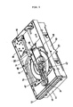
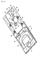
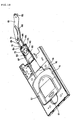
- FIG. 1 and FIG. 2 are drawings showing the overall structure of the disk recording and reproduction apparatus of the first embodiment of the present invention.
- This apparatus has an outer case 10 made of a flat rectangular parallelepiped. The upper section is open here as shown in FIG. 1 and FIG. 2.
- a longitudinal slot 12 is formed in a front panel 11 for sealing the opening on the front side of this outer case 10.
- a tray 13 capable of being pulled out from this longitudinal slot 12 is assembled into the inside of the outer case 10.
- the tray 13 has a concavity 14 formed in the middle section to receive the cartridge or the bare disk.
- the tray 13 is also formed with an opening 15 extending vertically so as to cross the concavity 14.
- the inner side of this opening 15 is formed with a U-shaped notch 16 and the nearer side is formed with a semicircular notch 17.
- a drive unit 18 is formed on a side section of the inner side of the tray 13.
- a motor 19 is installed to drive the drive unit 18.
- the tray 13 is supported by a step 20 on both sides of the inner sides of the outer case 10.
- a pinion comprising the output end of the drive unit 18 engages with a rack 21 on the lower side of the step 20, so the longitudinal slot 12 can in this way be pulled out or stored freely as shown by FIG. 1 and FIG. 2.
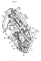
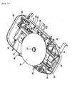
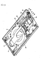
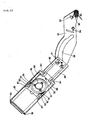
- a base unit 25 is installed on the upper section of the bottom plate of the outer case 10 as shown in FIG. 3 through FIG. 6.
- the base unit is made from a chassis of sheet metal.
- a turntable 27 is installed approximately in the center of that chassis supported by a bracket 26. The turntable 27 is directly driven by a motor below it.
- a DVD pickup 31 is installed on the nearer side and a DVR pickup 32a is installed on the inner side of the turntable 27 in the base unit 25.
- This DVD pickup is supported on both sides by a guide rod 33 and a feed screw 34.
- the feed screw 34 is driven by a stepping motor 35 and the DVD pickup is in this way moved along the radius of the optical disk.
- the DVR pickup 32 on the inner side is guided by a pair of guide rods 37 and 38 provided on both sides.
- a feed screw 39 is installed for moving the DVR pickup 32 along the radius of the optical disk. This feed screw 39 is driven by a stepping motor 40 and engages with a nut 41 of the pickup 32.
- a pair of support rods 45 are installed on both sides at the front on the base unit 25 and a support arm 46 is installed on both sides at the rear.
- these support rods 45 and support arm 46 protrude from the openings 47 and 48, and the DVR cartridge 51 on the tray 13 is supported by the four corners of the tray from the bottom.
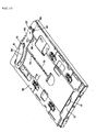
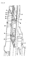
- a holder plate 60 is installed to shut the opening on the upper section of the outer case 10 as shown in FIG. 13 and FIG. 14.
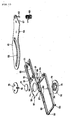
- a drive arm 61 that rotates centered around a pin 62 is installed on the holder plate 60 as shown in FIG. 13.
- a torsion coil spring 63 is installed on the outer circumference of the pin 62 for the drive arm 61 as shown in FIG. 15 and FIG. 16. The arm of this torsion coil spring 63 makes press-contact with the protrusion piece 67 installed on the drive arm 61.
- a pin 64 is installed so as to protrude into the bottom surface of the drive arm 61. This pin 64 is held by an arc-shaped opening 65 formed in the holder plate 60 (See FIG. 13). The leading edge section of the drive arm 61 contains an arc-shaped opening 66 with a comparatively large curve radius.
- a holder 70 for the clamping device can be installed on the lower side of the holder plate 60.
- a pair of pins 71 and 72 with flanges are installed on the holder 70 as shown in FIG. 15. These pins 71 and 72 engage with the line-shaped slit 73 of the holder plate 60. In particular, the pin 71 further engages with the arc-shaped opening 66 of the drive arm 61. Therefore, when the drive arm 61 is driven to rotate, the holder 70 is linearly moved along the line-shaped slit 73 of the holder plate 60.
- a circular opening 74 is formed in the holder 70 and the upper and lower clamp rings 75 and 76 are installed so as to sandwich the clamp plate 77 by way of this circular opening 74.
- the upper clamp ring 75 has three hooks 78 formed along the circumferential direction at 120 degree intervals to protrude downward. These hooks 78 are inserted into engaging holes 79 installed at 120 degree intervals along the circumferential direction of the clamp ring 76 and fastened.
- the pair of clamp rings 75 and 76 and the clamp plate 77 installed on the holder 70 comprise the clamping mechanism and clamp the bare disk 52 from above.
- a retractor 83 is also installed on the holder 70.
- the retractor 83 is a frame made from plastic.
- the rear edge has a pair of posts 84 with flanges.
- the posts 84 engage within the slits 85 on both sides of the holder 70 so as to slide along the slits.
- the flange section of the posts 84 are inserted into the slits 85 by way of an enlarged section 86 on the front end of the slit 85.
- the lower surface of the front edge side of the retractor 83 engages with the stop pieces 87 formed to protrude on both sides to the front end of the holder 70 (See FIG. 20 and FIG. 21). This kind of structure allows the retractor 83 to be coupled to the holder 70 to allow movement along its length.
- the retractor 83 is made from a molded plastic piece and contains two elastic pieces 90 at an intermediate position on both sides along its length.
- the elastic pieces 90 engage with the engaging concavity 91 formed on both sides at an intermediate position of the holder 70 or engage with the engaging concavity 92 formed on both sides at the leading edge side of the holder 70.
- the retractor 83 has a pair of hooks 93 that protrude downward in the front edge side. The hooks 93 are pressed on by the walls of the front end side of the DVR cartridge 51 and the retraction operation is performed in this way.
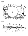
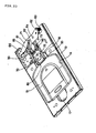
- the tray 13 is pulled into the outer case 10 while loaded with a DVR cartridge 51 in the concavity 14 of the tray 13 as shown in FIG. 2, the DVR cartridge 51 is loaded into the apparatus as shown in FIG. 1 through FIG. 9 .
- the DVD pickup 31 is then retracted at this time by the stepping motor 35 and the feed screw 34 to the outer circumferential side which is a section on the forward side of the tray 13.
- the DVR cartridge 51 is supported at this time respectively by the pair of support rods 45 and the pair of support arms 46 of the base unit 25. These rods 45 and arms 46 are all brought up through the openings 47 and 48 of tray 13 to the concavity 14 of tray 13 by the elevating operation of the base unit 25, and the DVR cartridge 51 is correctly positioned.
- the tray 13 is pulled into the device while the bare disk 52 is loaded on the concavity 14 of tray 13, the tray 13 is pulled into the outer case 10.
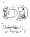
- the positional relation of the bare disk 52 on the base unit 25 at this time is shown in FIG. 10 through FIG. 12.
- the feed screw 39 retracts the DVR pickup 32 to a section on the inner side of tray 13 by utilizing the stepping motor 40, and the DVR pickup 32 is positioned on the outer circumferential side of the bare disk 52.
- the above scheme is contrived to retract the DVR pickup 32 so that at least the lens section cannot enter the inner side of the light projection area of base unit 25 holding the bare disk 52.
- the DVD pickup 31 is positioned on the lower side of the bare disk 52 by way of the feed screw 34 by the stepping motor 35.
- the bare disk 52 is rotated in this state by the turntable 27, and recording and reproduction of the bare disk 52 performed.
- the recording and reproduction apparatus of the present embodiment is capable of using disk recording media consisting of two mutually incompatible disk formats, namely DVD/CD and DVR.
- the base unit 25 is made of sheet metal or plastic and installed within the outer case 10 of this apparatus.
- the DVD/CD optical pickup 31 may be installed on the nearer side or the forward side in the base unit 25, and the DVR optical pickup 32 may be installed on the inner side.
- the optical disk motor and the turntable 27 are utilized as one common unit, and the two types of optical pickups 31 and 32 at positions 180 degrees apart in the circumferential direction of the turntable 27 are respectively movable along the radius of the optical disk. The tilt and positions of each of the two types of optical pickups 31 and 32 can be adjusted.
- the DRV pickup 32 which is an optical pickup for a high density recording format susceptible to dust, may be installed to the rear of the base unit 25 so its position is on the inner side of the outer case 10 as a dust countermeasure.
- the main spindle or sub-spindle of any of the guides 33, 37 and 38 for moving the two types of optical pickups 31 and 32 have been consolidated into at least one spindle in order to reduce the number of parts.
- guide rods 37 and 38 are installed in this apparatus to move the DVR optical pickup 32 in a level position to the opposite side of the turntable 27.
- These guide rods 37, 38 are parts necessary for moving the DVR optical pickup 32 in the radius direction of the optical disk inside the cartridge when the DVR optical pickup 32 accesses the DVR cartridge 51.
- these guide rods 37 and 38 slightly longer, a mechanism for retracting the DVR optical pickup 32 can be obtained.
- the length of the guide rod 33 and the feed screw 34 are increased to move the DVD/CD pickup 31 to the outer circumferential side of the turntable 27 on the opposite side.
- the guide rod 33 and the feed screw 34 are parts required when the DVD/CD pickup 31 is accessing the bare disk 52. However, making these guide rods 33 and 34 slightly longer allows the DVD pickup to be retracted.
- a pair of optical pickups 31 and 32 were installed at the nearer side and inner side of the base unit 25 at positions 180 degrees apart from each other along the circumferential direction of the turntable 27.
- the two types of optical pickups 31 and 32 need not always have this 180-degree positional relationship.
- the two optical pickups 31 and 32 may be installed in directions at right angle to each other so as to be movable, or they may be set at any desired angles, for example, at intersecting angles of 60 degrees in their direction of movement.
- the positions for directional movement of these two types of optical pickups 31 and 32 can be selected according to the relation with other components inside the outer case 10 or the base unit 25.
- a torsion coil spring 63 wound on a support pin 62 of the drive arm 61 applies a force in the counterclockwise direction centering on the pin 62 of the drive arm 61 in FIG. 17. So while the tray 13 is pulled out, the holder 70 engages with the arc-shaped opening 66 of the drive arm 61 by way of the pin 71, and the other pin 72 is in direct contact with the end edge of the line-shaped slit 73 of the holder plate 60. In other words, the holder 70 is pressed outward to the forward-most position.
- the retractor 83 capable of movement while combined with the holder 70 has elastic pieces 90 engaging with the concavity 92 of the front end of the holder plate 60. This occurs because the when the tray 13 is pulled out as shown in FIG. 17 and FIG. 18, the engaging piece 98 (See FIG. 22) installed at the rear end of tray 13 catches on the hook 93 of retractor 83 and is pulled to the forward side with the movement of the tray 13.
- the position of the elastic piece 90 of retractor 83 changes from a position that engages with the engaging concavity 92 of holder 70 to a position engaging with the concavity 91.
- the retractor 83 then retracts along with the holder 70.
- the drive arm 61 linked to this holder 70 by way of the pin 71 is pressed back rearward while opposing the force of the torsion coil spring 63.
- elastic energy is accumulated in the torsion coil spring 63.
- the pin 64 of the drive arm 61 is pressed into a shallow concavity 101 (See FIG. 14) formed on the rear end side of tray 13.
- the hook 93 of the retractor 83 is in this way separated slightly from the wall surface of the leading edge of the DVR cartridge 51 (side where it is inserted).
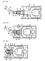
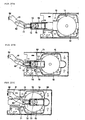
- the operation for retracting the clamping mechanism is shown in FIG. 26A through FIG. 26C.
- a torsion coil spring 63 is installed in the drive arm 61.
- the torsion coil spring 63 functions to press the disk clamping mechanism back.
- the positioning of the cartridge 51 is adversely affected.
- a shallow concavity 101 installed in the innermost part of tray 13 presses on the pin 64 installed on the lower edge of the drive arm 61 immediately prior to loading of the tray 13, so that the cartridge 51 is freed from the retractable disk clamping mechanism during clamping of the disk.
- the spring force of the torsion coil spring 63 of the drive arm 61 pushes the clamping mechanism back to the forward side specified position as the tray 13 is ejected.
- the engaging piece 97 formed on the tray 13 catches the hook 93 of the retractor 83 as shown in FIG. 22, and extends the retractor 83 to the specified position.
- a slope 97 is formed on the root of the extension hook 93 of the retractor 83 for engaging with the engaging piece of tray 13 since variations or irregularities might occur in the ejection stroke for the tray 13. This slope 97 functions as a limiter on the variations in the ejection stroke.
- the hook 93 section which catches the leading edge of retractor 83 of cartridge 51 when the ejection of the tray 13 is complete, is unaffected by variations (irregularities) in the tray 13 ejection stroke and is positioned on the outer circumferential side of the bare disk 52 contour (FIG. 27C).
- the present invention is not limited to these examples and the technical concepts of the present invention may encompass all types of changes and adaptations.
- the invention described above relates to an optical disk player for performing recording or reproduction by utilizing an optical pickup to access a disk recording medium comprised of an optical disk.
- the present invention is not limited to a recording and reproduction apparatus utilizing an optical pickup and is widely applicable to all types of disk recording and reproduction apparatus including magneto-optical disks, magnetic disks and electrostatic disks. Also pickups having functions corresponding to the respective recording and reproduction method are of course also applicable to the present invention.
- this disk recording and reproduction apparatus is comprised of a rotating drive means for driving multiple types of disk record media of different formats and, multiple pickups respectively installed for said multiple types of disk record media of different formats .
- the disk recording and reproduction apparatus of this invention therefore drives multiple types of disk recording media of different formats by utilizing a rotating drive means and also performs recording and/or reproduction by means of a corresponding pickup.
- This device can therefore perform recording and/or reproduction of multiple types of disk media with a minimal structure of mechanism.
- this disk recording and reproduction apparatus is comprised of an installation means to selectively install a cartridge type disk recording medium and bare disk type recording medium and, a clamping means to clamp the bare disk type recording medium and, a drive means to drive the clamping means when the cartridge type disk recording means has been installed.
- the clamping mechanism is moved to a non-operating position when a cartridge type disk recording medium has been loaded.
- a clamping means reliably clamps this bare disk type disk recording medium and recording and/or reproduction is performed.
Landscapes
- Physics & Mathematics (AREA)
- Optics & Photonics (AREA)
- Holding Or Fastening Of Disk On Rotational Shaft (AREA)
- Feeding And Guiding Record Carriers (AREA)
- Optical Head (AREA)
- Moving Of Heads (AREA)
- Optical Recording Or Reproduction (AREA)
- Moving Of The Head For Recording And Reproducing By Optical Means (AREA)
Applications Claiming Priority (3)
| Application Number | Priority Date | Filing Date | Title |
|---|---|---|---|
| JP2001257125 | 2001-08-28 | ||
| JP2001257125A JP2003067920A (ja) | 2001-08-28 | 2001-08-28 | ディスク式記録再生装置 |
| PCT/JP2002/006609 WO2003021594A1 (fr) | 2001-08-28 | 2002-06-28 | Dispositif de reproduction et d'enregistrement de type a disque |
Publications (3)
| Publication Number | Publication Date |
|---|---|
| EP1343165A1 true EP1343165A1 (fr) | 2003-09-10 |
| EP1343165A4 EP1343165A4 (fr) | 2006-11-08 |
| EP1343165B1 EP1343165B1 (fr) | 2009-03-18 |
Family
ID=19084835
Family Applications (1)
| Application Number | Title | Priority Date | Filing Date |
|---|---|---|---|
| EP02741370A Expired - Lifetime EP1343165B1 (fr) | 2001-08-28 | 2002-06-28 | Dispositif de reproduction et d'enregistrement de type a disque |
Country Status (7)
| Country | Link |
|---|---|
| US (1) | US6964056B2 (fr) |
| EP (1) | EP1343165B1 (fr) |
| JP (1) | JP2003067920A (fr) |
| KR (1) | KR100898425B1 (fr) |
| CN (1) | CN100414638C (fr) |
| DE (1) | DE60231595D1 (fr) |
| WO (1) | WO2003021594A1 (fr) |
Cited By (1)
| Publication number | Priority date | Publication date | Assignee | Title |
|---|---|---|---|---|
| EP1926099A2 (fr) | 2006-11-24 | 2008-05-28 | Sony Corporation | Dispositif de réproduction |
Families Citing this family (5)
| Publication number | Priority date | Publication date | Assignee | Title |
|---|---|---|---|---|
| KR100467602B1 (ko) * | 2002-08-07 | 2005-01-24 | 삼성전자주식회사 | 디스크 플레이어의 디스크 가이드 장치 |
| JP2004310933A (ja) * | 2003-04-09 | 2004-11-04 | Sony Corp | ディスクドライブ装置 |
| CN1540651A (zh) * | 2003-04-23 | 2004-10-27 | ���µ�����ҵ��ʽ���� | 托盘和记录再现装置 |
| JP2005116036A (ja) | 2003-10-06 | 2005-04-28 | Sony Corp | ディスクドライブ装置 |
| JP4163670B2 (ja) | 2004-05-10 | 2008-10-08 | 株式会社ソニー・コンピュータエンタテインメント | ディスク装置 |
Family Cites Families (12)
| Publication number | Priority date | Publication date | Assignee | Title |
|---|---|---|---|---|
| JP2626205B2 (ja) | 1990-08-09 | 1997-07-02 | 松下電器産業株式会社 | 光学的情報記録/再生装置およびカートリッジ |
| JP3106874B2 (ja) * | 1993-09-29 | 2000-11-06 | 松下電器産業株式会社 | 円盤記録再生装置 |
| JP2882989B2 (ja) * | 1993-12-29 | 1999-04-19 | 株式会社ケンウッド | 光ディスク記録再生装置 |
| JP3367088B2 (ja) | 1994-02-25 | 2003-01-14 | 日本ビクター株式会社 | Md−cdコンパチブルプレーヤ |
| JP3088243B2 (ja) * | 1994-08-18 | 2000-09-18 | 株式会社ケンウッド | 光ディスク記録再生装置 |
| JPH09282671A (ja) * | 1996-04-05 | 1997-10-31 | Sony Corp | 円盤状光記録媒体の記録及び/又は再生装置 |
| US6538971B2 (en) * | 1997-12-23 | 2003-03-25 | Samsung Electronics Co., Ltd. | Optical information recording/reproducing apparatus and method for using both disc cartridges holding 8cm and 12cm disc |
| JPH11219557A (ja) | 1998-02-02 | 1999-08-10 | Sony Corp | 光ディスク保持装置 |
| EP0992990A3 (fr) * | 1998-10-08 | 2000-10-25 | Pioneer Corporation | Lecteur de disque à chargement frontal |
| JP2000228017A (ja) * | 1999-02-08 | 2000-08-15 | Pioneer Electronic Corp | 記録再生装置 |
| WO2000048184A1 (fr) * | 1999-02-12 | 2000-08-17 | Mitsubishi Denki Kabushiki Kaisha | Unite de disque |
| EP1087388A4 (fr) * | 1999-02-12 | 2004-08-04 | Mitsubishi Electric Corp | Unite de disque |
-
2001
- 2001-08-28 JP JP2001257125A patent/JP2003067920A/ja not_active Abandoned
-
2002
- 2002-06-28 CN CNB028031504A patent/CN100414638C/zh not_active Expired - Fee Related
- 2002-06-28 US US10/415,221 patent/US6964056B2/en not_active Expired - Fee Related
- 2002-06-28 EP EP02741370A patent/EP1343165B1/fr not_active Expired - Lifetime
- 2002-06-28 WO PCT/JP2002/006609 patent/WO2003021594A1/fr not_active Ceased
- 2002-06-28 KR KR1020037005752A patent/KR100898425B1/ko not_active Expired - Fee Related
- 2002-06-28 DE DE60231595T patent/DE60231595D1/de not_active Expired - Fee Related
Cited By (3)
| Publication number | Priority date | Publication date | Assignee | Title |
|---|---|---|---|---|
| EP1926099A2 (fr) | 2006-11-24 | 2008-05-28 | Sony Corporation | Dispositif de réproduction |
| EP1926099A3 (fr) * | 2006-11-24 | 2010-12-15 | Sony Corporation | Dispositif de réproduction |
| US8671421B2 (en) | 2006-11-24 | 2014-03-11 | Sony Corporation | Reproducing device |
Also Published As
| Publication number | Publication date |
|---|---|
| DE60231595D1 (de) | 2009-04-30 |
| JP2003067920A (ja) | 2003-03-07 |
| US6964056B2 (en) | 2005-11-08 |
| WO2003021594A1 (fr) | 2003-03-13 |
| US20040013071A1 (en) | 2004-01-22 |
| EP1343165B1 (fr) | 2009-03-18 |
| KR100898425B1 (ko) | 2009-05-21 |
| HK1063240A1 (zh) | 2004-12-17 |
| CN1476611A (zh) | 2004-02-18 |
| CN100414638C (zh) | 2008-08-27 |
| KR20040029952A (ko) | 2004-04-08 |
| EP1343165A4 (fr) | 2006-11-08 |
Similar Documents
| Publication | Publication Date | Title |
|---|---|---|
| JP4543300B2 (ja) | ディスク式記録および/または再生装置 | |
| EP0661701B1 (fr) | Appareil d'enregistrement/reproduction de disque optique | |
| US5995469A (en) | Disk device having movable cartridge holder and a cam plate having a cam groove with three successive inclined cam groove portions | |
| US6964056B2 (en) | Disk type recording and reproducing device | |
| EP1465178B1 (fr) | Mécanisme de fermeture et appareil d' entraînement de disque | |
| US7281254B2 (en) | Optical disc drive having a traverse holder that is rotatable around an axis that is mutually different from the axis of a traverse base | |
| HK1063240B (en) | Disk type recording and reproducing device | |
| US20040244020A1 (en) | Disk recording and reproducing device | |
| JP3613012B2 (ja) | ディスクチェンジャー装置 | |
| JP3506073B2 (ja) | ディスク装置 | |
| JPH10283710A (ja) | ディスク記録及び/又は再生装置 | |
| CN101211609A (zh) | 光盘装置 | |
| JP2000298907A (ja) | ローディング装置 | |
| JP2000276739A (ja) | 光学ディスク装置 | |
| JP2001344866A (ja) | 記憶装置 | |
| JP2001216761A (ja) | ディスク駆動装置 | |
| JPH10275391A (ja) | ディスク装置 | |
| JP2003115176A (ja) | ディスク式記録再生装置 | |
| JP2007128621A (ja) | ディスクドライブ装置 | |
| HK1018114A (en) | Cartridge loading apparatus with improved base plate and cartridge receiver latch | |
| HK1018113A (en) | Cartridge loading apparatus with tilting bias coil assembly | |
| JPH09120627A (ja) | ディスク記録再生装置 | |
| JPH10228704A (ja) | 記録媒体ローディング機構 | |
| HK1018112A (en) | Cartridge loading apparatus with improved parking arm | |
| HK1018115A (en) | Cartridge loading apparatus with improved cartridge receiver |
Legal Events
| Date | Code | Title | Description |
|---|---|---|---|
| PUAI | Public reference made under article 153(3) epc to a published international application that has entered the european phase |
Free format text: ORIGINAL CODE: 0009012 |
|
| 17P | Request for examination filed |
Effective date: 20030429 |
|
| AK | Designated contracting states |
Kind code of ref document: A1 Designated state(s): AT BE CH CY DE DK ES FI FR GB GR IE IT LI LU MC NL PT SE TR |
|
| A4 | Supplementary search report drawn up and despatched |
Effective date: 20061011 |
|
| 17Q | First examination report despatched |
Effective date: 20070705 |
|
| GRAP | Despatch of communication of intention to grant a patent |
Free format text: ORIGINAL CODE: EPIDOSNIGR1 |
|
| GRAS | Grant fee paid |
Free format text: ORIGINAL CODE: EPIDOSNIGR3 |
|
| GRAA | (expected) grant |
Free format text: ORIGINAL CODE: 0009210 |
|
| AK | Designated contracting states |
Kind code of ref document: B1 Designated state(s): DE FR GB |
|
| REG | Reference to a national code |
Ref country code: GB Ref legal event code: FG4D |
|
| REF | Corresponds to: |
Ref document number: 60231595 Country of ref document: DE Date of ref document: 20090430 Kind code of ref document: P |
|
| PGFP | Annual fee paid to national office [announced via postgrant information from national office to epo] |
Ref country code: GB Payment date: 20090624 Year of fee payment: 8 Ref country code: DE Payment date: 20090626 Year of fee payment: 8 |
|
| PLBE | No opposition filed within time limit |
Free format text: ORIGINAL CODE: 0009261 |
|
| STAA | Information on the status of an ep patent application or granted ep patent |
Free format text: STATUS: NO OPPOSITION FILED WITHIN TIME LIMIT |
|
| 26N | No opposition filed |
Effective date: 20091221 |
|
| GBPC | Gb: european patent ceased through non-payment of renewal fee |
Effective date: 20100628 |
|
| REG | Reference to a national code |
Ref country code: FR Ref legal event code: ST Effective date: 20110228 |
|
| PG25 | Lapsed in a contracting state [announced via postgrant information from national office to epo] |
Ref country code: DE Free format text: LAPSE BECAUSE OF NON-PAYMENT OF DUE FEES Effective date: 20110101 |
|
| PG25 | Lapsed in a contracting state [announced via postgrant information from national office to epo] |
Ref country code: FR Free format text: LAPSE BECAUSE OF NON-PAYMENT OF DUE FEES Effective date: 20100630 |
|
| PG25 | Lapsed in a contracting state [announced via postgrant information from national office to epo] |
Ref country code: GB Free format text: LAPSE BECAUSE OF NON-PAYMENT OF DUE FEES Effective date: 20100628 |
|
| PGFP | Annual fee paid to national office [announced via postgrant information from national office to epo] |
Ref country code: FR Payment date: 20090611 Year of fee payment: 8 |