EP1344927A2 - Culasse - Google Patents
Culasse Download PDFInfo
- Publication number
- EP1344927A2 EP1344927A2 EP03251474A EP03251474A EP1344927A2 EP 1344927 A2 EP1344927 A2 EP 1344927A2 EP 03251474 A EP03251474 A EP 03251474A EP 03251474 A EP03251474 A EP 03251474A EP 1344927 A2 EP1344927 A2 EP 1344927A2
- Authority
- EP
- European Patent Office
- Prior art keywords
- cylinder head
- rear end
- sub
- end wall
- cam chamber
- Prior art date
- Legal status (The legal status is an assumption and is not a legal conclusion. Google has not performed a legal analysis and makes no representation as to the accuracy of the status listed.)
- Granted
Links
- XLYOFNOQVPJJNP-UHFFFAOYSA-N water Substances O XLYOFNOQVPJJNP-UHFFFAOYSA-N 0.000 claims description 19
- 238000005266 casting Methods 0.000 claims description 3
- 239000003921 oil Substances 0.000 description 15
- 239000000446 fuel Substances 0.000 description 5
- 238000007789 sealing Methods 0.000 description 2
- 238000005452 bending Methods 0.000 description 1
- 238000002485 combustion reaction Methods 0.000 description 1
- 239000000498 cooling water Substances 0.000 description 1
- 239000007788 liquid Substances 0.000 description 1
- 239000010687 lubricating oil Substances 0.000 description 1
- 238000004519 manufacturing process Methods 0.000 description 1
- 239000002184 metal Substances 0.000 description 1
- 238000012986 modification Methods 0.000 description 1
- 230000004048 modification Effects 0.000 description 1
Images


Classifications
-
- F—MECHANICAL ENGINEERING; LIGHTING; HEATING; WEAPONS; BLASTING
- F01—MACHINES OR ENGINES IN GENERAL; ENGINE PLANTS IN GENERAL; STEAM ENGINES
- F01M—LUBRICATING OF MACHINES OR ENGINES IN GENERAL; LUBRICATING INTERNAL COMBUSTION ENGINES; CRANKCASE VENTILATING
- F01M11/00—Component parts, details or accessories, not provided for in, or of interest apart from, groups F01M1/00 - F01M9/00
- F01M11/02—Arrangements of lubricant conduits
-
- F—MECHANICAL ENGINEERING; LIGHTING; HEATING; WEAPONS; BLASTING
- F02—COMBUSTION ENGINES; HOT-GAS OR COMBUSTION-PRODUCT ENGINE PLANTS
- F02F—CYLINDERS, PISTONS OR CASINGS, FOR COMBUSTION ENGINES; ARRANGEMENTS OF SEALINGS IN COMBUSTION ENGINES
- F02F7/00—Casings, e.g. crankcases
- F02F7/006—Camshaft or pushrod housings
Definitions
- the present invention relates to the structure of a cylinder head that constitutes an internal combustion engine for automobiles or for industrial machines.
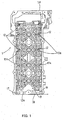
- a cylinder head 1 on a cylinder head 1 are rotatably provided two camshafts 3, 4 for intake and for exhaust respectively through cam brackets 2, 2.
- camshafts 3, 4 On the front ends of the camshafts 3, 4 are respectively provided timing sprockets 6, 6, and each of the camshafts 3, 4 is provided with a plurality of cams 5, 5 for valve driving.
- the rear end of the camshaft 3 on the left of the drawing has been extended rearward as an extension 3a, and accordingly the length of the left camshaft 3 is longer than that of the right one 4.
- This extension 3a is provided with a fuel pump cam 7 for driving the fuel pump and also on the rear end of the extension 3a is mounted a cam angle sensor plate 8 for detecting the cam angle.
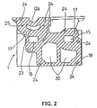
- a sub-bearing portion 12a On the sub-bearing portion 12a is mounted a sub-cam bracket 2a with bolts to prevent bending of the camshaft 3.
- the cylinder head 1 is provided with a sub-cam chamber 10 formed as a unit, which covers the rear part of the extension 3a of the camshaft 3.
- the sub-cam chamber 10 is projected, so that manufacture of the cylinder head 1 becomes extremely difficult.
- the present invention is worked out in view of the above-described problems in the prior art. It is an object of the present invention to provide a cylinder head that can surely return the oil within the sub-cam chamber provided outside the rear end wall into the inside of the cylinder head.
- the subject matter of the present invention is that in a cylinder head having the structure where two camshafts for intake and for exhaust are provided respectively on the top, one of which camshafts has an extension for providing a fuel pump cam made by extending the rear end opposite the timing sprocket, the front and the rear end wall are formed in parallel; the extension of the camshaft is disposed outside the rear end wall; a separate cover member is mounted on the outside of the rear end wall to form a sub-cam chamber for covering the extension; and an oil-returning hole is formed through the rear end wall so as to return the oil within the sub-cam chamber into the inside of the rear end wall.
- FIG. 1 is a plan view of a cylinder head
- FIG. 2 is an enlarged rear end view of FIG.1
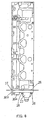
- FIG.3 is a right side view of FIG.1.
- FIG.4 is a plan view of the cylinder head on which an integrated unit of cover member and water outlet is mounted.
- FIG.5 and FIG.6 are an enlarged rear end view and a right side view of FIG.4 respectively.
- a cylinder head 1 is provided with two camshafts for intake and for exhaust (not shown) on the top, one of which camshafts has an extension for providing a fuel pump cam (not shown) made by extending the rear end opposite the timing sprocket (not shown).
- a sub-bearing portion 12a for supporting the extension is provided on the cylinder head 1. This sub-bearing portion 12a is formed as a unit on the top of the rear end wall of the cylinder head 1.
- the rear end wall of the cylinder head 1, which is a water outlet-mounting surface 19, is formed in parallel to the front-end wall 1a of the cylinder head 1,
- a cover member 30, which is to be mounted on the rear end wall as a separate unit, forms the sub-cam chamber 10.
- the cover member 30 is made previously together with a water outlet 22 as a unit and mounted on the water outlet-mounting surface 19 with bolts,
- water jacket openings 20, 20 In the rear end wall or water outlet surface 19 of the cylinder head 1 is formed water jacket openings 20, 20 to circulate the cooling water, to which the water outlet 22 is connected.
- the water outlet 22 is disposed in a separate position from the sub-cam chamber-forming portion 30a, and thereby it is prevented that the longitudinal length of the cylinder head 1 becomes too long.
- the water outlet 22 is formed integrally with the cover member 30.
- the cover member 30 is integrally composed of a sub-cam chamber- forming portion 30a that forms a sub-cam chamber 10 on the mounted condition and a core hole-closing portion 30b that is capable of closing the core-supporting holes 15, 15 of a valve case 9 (see FIG.5).
- the sub-cam chamber-forming portion 30a and core hole-closing portion 30b are made as a unit together with the water outlet 22,
- This core hole-closing portion 30b is formed in a flat plate with thickness less than the size of the sub-cam chamber forming portion 30a protruding from the rear end wall. Accordingly, the entire length of the cylinder head 1 is prevented from becoming larger size.
- a sub-bearing portion 12a On the top of the cylinder head 1 is formed a plurality of bearing portions 12, 12 in hollow fashion and on the top of the rear end wall, or the water outlet-mounting surface 19, is disposed a sub-bearing portion 12a. Under the sub-bearing portion 12a of the water outlet-mounting surface 19 is pierced through an oil return hole 23 to return the oil accumulated in the sub-cam chamber 10 into the valve case 9.
- each oil supply passage 17 is provided with a branch passage 17a facing on each bearing portion 12 or 12a.
- a plurality of mounting boltholes 24, 24 On the rear end wall are provided a plurality of mounting boltholes 24, 24.
- the integrated unit of cover member 30 and water outlet 22 is mounted on the rear end wall by tightening mounting bolts 28, 28 into the mounting boltholes 24, 24.
- a metal gasket 26 On the water outlet mounting surface 19 is placed a metal gasket 26 for sealing.
- liquid gasket 27 Also on the mated surfaces at the upper part, where chamfering is performed, is applied liquid gasket 27 for sealing.
- the sub-cam chamber-forming portion 30a of the cover member 30 can form the sub-cam chamber 10 on the outside of the rear end wall.
- the extension 3a of the camshaft 3 is disposed within this sub-cam chamber 10.
- the sub-cam chamber-forming portion 30a covers the extension 3a protruded outside from the cylinder head 1.
- the core hole-closing portion 30b of the cover member 30 closes the core-supporting holes 15, 15 used at the time of casting the valve case 9 and the rear ends of the oil passages 17, 17.
- the sub-bearing portion 12a for the extension 3a and the sub-cam bracket 2a are satisfactorily lubricated by oil that is sufficiently supplied through the oil passage 17. Besides, it is possible that the oil accumulated in the sub-cam chamber 10 is surely returned through an oil-returning hole 23 into the valve case 9 in the cylinder head 1, so that the oil is smoothly circulated.
- the separate cover member 30 is mounted on the rear end wall 19 of the cylinder head 1 favorably to form the sub-cam chamber 10. Further, the oil-returning hole 23 is formed through the cylinder head 1 so as to communicate with the inside of this sub-cam chamber 10, As a result, it is possible to surely return the oil through the oil-returning hole 23 into the cylinder head 1.
Landscapes
- Engineering & Computer Science (AREA)
- Mechanical Engineering (AREA)
- General Engineering & Computer Science (AREA)
- Chemical & Material Sciences (AREA)
- Combustion & Propulsion (AREA)
- Cylinder Crankcases Of Internal Combustion Engines (AREA)
- Lubrication Of Internal Combustion Engines (AREA)
Applications Claiming Priority (2)
| Application Number | Priority Date | Filing Date | Title |
|---|---|---|---|
| JP2002066123 | 2002-03-11 | ||
| JP2002066123A JP3721468B2 (ja) | 2002-03-11 | 2002-03-11 | シリンダヘッド構造 |
Publications (3)
| Publication Number | Publication Date |
|---|---|
| EP1344927A2 true EP1344927A2 (fr) | 2003-09-17 |
| EP1344927A3 EP1344927A3 (fr) | 2003-12-10 |
| EP1344927B1 EP1344927B1 (fr) | 2007-10-10 |
Family
ID=27764475
Family Applications (1)
| Application Number | Title | Priority Date | Filing Date |
|---|---|---|---|
| EP20030251474 Expired - Lifetime EP1344927B1 (fr) | 2002-03-11 | 2003-03-10 | Culasse |
Country Status (3)
| Country | Link |
|---|---|
| EP (1) | EP1344927B1 (fr) |
| JP (1) | JP3721468B2 (fr) |
| DE (1) | DE60316740T2 (fr) |
Cited By (1)
| Publication number | Priority date | Publication date | Assignee | Title |
|---|---|---|---|---|
| RU2507404C1 (ru) * | 2012-06-26 | 2014-02-20 | Открытое акционерное общество "Автодизель" (Ярославский моторный завод) | Модуль двигателя внутреннего сгорания, корпус модуля и двигатель внутреннего сгорания |
Families Citing this family (2)
| Publication number | Priority date | Publication date | Assignee | Title |
|---|---|---|---|---|
| JP4386112B2 (ja) | 2007-07-20 | 2009-12-16 | トヨタ自動車株式会社 | エンジン |
| US8397689B2 (en) | 2010-05-17 | 2013-03-19 | GM Global Technology Operations LLC | Fuel pump tappet/roller follower lubrication |
Citations (1)
| Publication number | Priority date | Publication date | Assignee | Title |
|---|---|---|---|---|
| JP2001304063A (ja) | 2000-04-27 | 2001-10-31 | Suzuki Motor Corp | 内燃機関のフューエルポンプ取付構造 |
Family Cites Families (3)
| Publication number | Priority date | Publication date | Assignee | Title |
|---|---|---|---|---|
| JPS59211754A (ja) * | 1983-05-18 | 1984-11-30 | Honda Motor Co Ltd | 内燃機関における燃料ポンプ駆動装置 |
| DE19650246A1 (de) * | 1996-12-04 | 1998-06-10 | Bosch Gmbh Robert | Von einer Welle eines Verbrennungsmotors angetriebene Kolbenpumpe |
| DE19701874C5 (de) * | 1997-01-21 | 2006-06-22 | Daimlerchrysler Ag | Nockenwellenlageranordnung im Zylinderkopf einer Brennkraftmaschine |
-
2002
- 2002-03-11 JP JP2002066123A patent/JP3721468B2/ja not_active Expired - Fee Related
-
2003
- 2003-03-10 EP EP20030251474 patent/EP1344927B1/fr not_active Expired - Lifetime
- 2003-03-10 DE DE2003616740 patent/DE60316740T2/de not_active Expired - Lifetime
Patent Citations (1)
| Publication number | Priority date | Publication date | Assignee | Title |
|---|---|---|---|---|
| JP2001304063A (ja) | 2000-04-27 | 2001-10-31 | Suzuki Motor Corp | 内燃機関のフューエルポンプ取付構造 |
Cited By (1)
| Publication number | Priority date | Publication date | Assignee | Title |
|---|---|---|---|---|
| RU2507404C1 (ru) * | 2012-06-26 | 2014-02-20 | Открытое акционерное общество "Автодизель" (Ярославский моторный завод) | Модуль двигателя внутреннего сгорания, корпус модуля и двигатель внутреннего сгорания |
Also Published As
| Publication number | Publication date |
|---|---|
| EP1344927B1 (fr) | 2007-10-10 |
| DE60316740T2 (de) | 2008-07-24 |
| DE60316740D1 (de) | 2007-11-22 |
| JP3721468B2 (ja) | 2005-11-30 |
| JP2003269243A (ja) | 2003-09-25 |
| EP1344927A3 (fr) | 2003-12-10 |
Similar Documents
| Publication | Publication Date | Title |
|---|---|---|
| US7717081B2 (en) | Engine cylinder head structure | |
| EP0374802B1 (fr) | Agencement de l'entraînement d'un arbre à cames pour moteur à combustion interne | |
| EP1344927B1 (fr) | Culasse | |
| EP1394371A3 (fr) | Pompe de graissage placée dans le carter à huile | |
| JPH0629530B2 (ja) | エンジンの潤滑装置 | |
| JP3695247B2 (ja) | 4サイクルエンジンの潤滑構造 | |
| US20040226528A1 (en) | Lubricating structure of OHC internal combustion engine | |
| JPH0988539A (ja) | オイルレベルゲージの取付構造 | |
| US6948471B1 (en) | Engine lubricating system | |
| JP2000204918A (ja) | エンジンのカムシャフト軸受部潤滑構造 | |
| JP3146535B2 (ja) | 4ストロークエンジンの潤滑オイル通路 | |
| JP2000045742A (ja) | 潤滑油吐出口 | |
| JP2007321692A (ja) | 内燃機関の冷却構造 | |
| JP2000282829A (ja) | タイミングチェーンの潤滑装置 | |
| JP3235159B2 (ja) | V型ohvエンジンの潤滑装置 | |
| US6935298B2 (en) | Lubricating device for motorcycle engine | |
| JP3821342B2 (ja) | 内燃機関のオイル通路構造 | |
| JP4246130B2 (ja) | 内燃機関のオイル通路配置構造 | |
| JP2001012225A (ja) | シリンダヘッドの潤滑系構造 | |
| JPS63201308A (ja) | デイ−ゼルエンジン | |
| JPS581610Y2 (ja) | 頭上弁式エンジンの潤滑装置 | |
| JP2630820B2 (ja) | Dohcエンジンのカム軸受潤滑装置 | |
| JPH0536971Y2 (fr) | ||
| JP2001115816A (ja) | エンジンのオイルレベルゲージガイド | |
| JP2516637Y2 (ja) | Dohcエンジンのシリンダヘッド |
Legal Events
| Date | Code | Title | Description |
|---|---|---|---|
| PUAI | Public reference made under article 153(3) epc to a published international application that has entered the european phase |
Free format text: ORIGINAL CODE: 0009012 |
|
| AK | Designated contracting states |
Kind code of ref document: A2 Designated state(s): AT BE BG CH CY CZ DE DK EE ES FI FR GB GR HU IE IT LI LU MC NL PT RO SE SI SK TR |
|
| AX | Request for extension of the european patent |
Extension state: AL LT LV MK |
|
| PUAL | Search report despatched |
Free format text: ORIGINAL CODE: 0009013 |
|
| AK | Designated contracting states |
Kind code of ref document: A3 Designated state(s): AT BE BG CH CY CZ DE DK EE ES FI FR GB GR HU IE IT LI LU MC NL PT RO SE SI SK TR |
|
| AX | Request for extension of the european patent |
Extension state: AL LT LV MK |
|
| RIC1 | Information provided on ipc code assigned before grant |
Ipc: 7F 02F 1/24 B Ipc: 7F 02F 7/00 B Ipc: 7F 02F 1/42 A Ipc: 7F 02M 37/06 B Ipc: 7F 02B 67/04 B Ipc: 7F 02M 39/02 B |
|
| 17P | Request for examination filed |
Effective date: 20040311 |
|
| AKX | Designation fees paid |
Designated state(s): DE FR GB |
|
| 17Q | First examination report despatched |
Effective date: 20061208 |
|
| GRAP | Despatch of communication of intention to grant a patent |
Free format text: ORIGINAL CODE: EPIDOSNIGR1 |
|
| GRAS | Grant fee paid |
Free format text: ORIGINAL CODE: EPIDOSNIGR3 |
|
| GRAA | (expected) grant |
Free format text: ORIGINAL CODE: 0009210 |
|
| AK | Designated contracting states |
Kind code of ref document: B1 Designated state(s): DE FR GB |
|
| REG | Reference to a national code |
Ref country code: GB Ref legal event code: FG4D |
|
| REF | Corresponds to: |
Ref document number: 60316740 Country of ref document: DE Date of ref document: 20071122 Kind code of ref document: P |
|
| ET | Fr: translation filed | ||
| PLBE | No opposition filed within time limit |
Free format text: ORIGINAL CODE: 0009261 |
|
| STAA | Information on the status of an ep patent application or granted ep patent |
Free format text: STATUS: NO OPPOSITION FILED WITHIN TIME LIMIT |
|
| 26N | No opposition filed |
Effective date: 20080711 |
|
| PGFP | Annual fee paid to national office [announced via postgrant information from national office to epo] |
Ref country code: DE Payment date: 20130306 Year of fee payment: 11 Ref country code: GB Payment date: 20130306 Year of fee payment: 11 Ref country code: FR Payment date: 20130325 Year of fee payment: 11 |
|
| REG | Reference to a national code |
Ref country code: DE Ref legal event code: R119 Ref document number: 60316740 Country of ref document: DE |
|
| GBPC | Gb: european patent ceased through non-payment of renewal fee |
Effective date: 20140310 |
|
| REG | Reference to a national code |
Ref country code: FR Ref legal event code: ST Effective date: 20141128 |
|
| REG | Reference to a national code |
Ref country code: DE Ref legal event code: R119 Ref document number: 60316740 Country of ref document: DE Effective date: 20141001 |
|
| PG25 | Lapsed in a contracting state [announced via postgrant information from national office to epo] |
Ref country code: DE Free format text: LAPSE BECAUSE OF NON-PAYMENT OF DUE FEES Effective date: 20141001 Ref country code: GB Free format text: LAPSE BECAUSE OF NON-PAYMENT OF DUE FEES Effective date: 20140310 Ref country code: FR Free format text: LAPSE BECAUSE OF NON-PAYMENT OF DUE FEES Effective date: 20140331 |