EP1344933A2 - Structure d'entraínement d'un compresseur linéaire - Google Patents
Structure d'entraínement d'un compresseur linéaire Download PDFInfo
- Publication number
- EP1344933A2 EP1344933A2 EP03013106A EP03013106A EP1344933A2 EP 1344933 A2 EP1344933 A2 EP 1344933A2 EP 03013106 A EP03013106 A EP 03013106A EP 03013106 A EP03013106 A EP 03013106A EP 1344933 A2 EP1344933 A2 EP 1344933A2
- Authority
- EP
- European Patent Office
- Prior art keywords
- yoke
- piston
- blocks
- stator
- linear motor
- Prior art date
- Legal status (The legal status is an assumption and is not a legal conclusion. Google has not performed a legal analysis and makes no representation as to the accuracy of the status listed.)
- Granted
Links
- 230000007246 mechanism Effects 0.000 claims abstract description 15
- 230000035699 permeability Effects 0.000 claims description 14
- 230000006835 compression Effects 0.000 claims description 10
- 238000007906 compression Methods 0.000 claims description 10
- 239000000463 material Substances 0.000 claims description 10
- 238000003475 lamination Methods 0.000 claims description 9
- 239000011347 resin Substances 0.000 claims description 6
- 229920005989 resin Polymers 0.000 claims description 6
- 230000008859 change Effects 0.000 claims description 5
- 230000002093 peripheral effect Effects 0.000 claims description 4
- 238000005304 joining Methods 0.000 claims description 3
- 230000004044 response Effects 0.000 claims description 3
- 230000010355 oscillation Effects 0.000 abstract description 11
- 230000003247 decreasing effect Effects 0.000 description 7
- 230000004048 modification Effects 0.000 description 5
- 238000012986 modification Methods 0.000 description 5
- RYGMFSIKBFXOCR-UHFFFAOYSA-N Copper Chemical compound [Cu] RYGMFSIKBFXOCR-UHFFFAOYSA-N 0.000 description 4
- 229910052802 copper Inorganic materials 0.000 description 4
- 239000010949 copper Substances 0.000 description 4
- 230000001965 increasing effect Effects 0.000 description 3
- 239000003507 refrigerant Substances 0.000 description 3
- 238000005057 refrigeration Methods 0.000 description 3
- 238000004804 winding Methods 0.000 description 3
- 230000015572 biosynthetic process Effects 0.000 description 2
- 230000004907 flux Effects 0.000 description 2
- 238000004519 manufacturing process Methods 0.000 description 2
- 238000001816 cooling Methods 0.000 description 1
- 230000000593 degrading effect Effects 0.000 description 1
- 230000002708 enhancing effect Effects 0.000 description 1
- 230000007613 environmental effect Effects 0.000 description 1
- 230000006870 function Effects 0.000 description 1
- 239000007788 liquid Substances 0.000 description 1
- 239000010687 lubricating oil Substances 0.000 description 1
- 238000003825 pressing Methods 0.000 description 1
- 125000006850 spacer group Chemical group 0.000 description 1
- 239000000725 suspension Substances 0.000 description 1
Images


Classifications
-
- H—ELECTRICITY
- H02—GENERATION; CONVERSION OR DISTRIBUTION OF ELECTRIC POWER
- H02K—DYNAMO-ELECTRIC MACHINES
- H02K33/00—Motors with reciprocating, oscillating or vibrating magnet, armature or coil system
- H02K33/16—Motors with reciprocating, oscillating or vibrating magnet, armature or coil system with polarised armatures moving in alternate directions by reversal or energisation of a single coil system
-
- F—MECHANICAL ENGINEERING; LIGHTING; HEATING; WEAPONS; BLASTING
- F04—POSITIVE - DISPLACEMENT MACHINES FOR LIQUIDS; PUMPS FOR LIQUIDS OR ELASTIC FLUIDS
- F04B—POSITIVE-DISPLACEMENT MACHINES FOR LIQUIDS; PUMPS
- F04B35/00—Piston pumps specially adapted for elastic fluids and characterised by the driving means to their working members, or by combination with, or adaptation to, specific driving engines or motors, not otherwise provided for
- F04B35/04—Piston pumps specially adapted for elastic fluids and characterised by the driving means to their working members, or by combination with, or adaptation to, specific driving engines or motors, not otherwise provided for the means being electric
- F04B35/045—Piston pumps specially adapted for elastic fluids and characterised by the driving means to their working members, or by combination with, or adaptation to, specific driving engines or motors, not otherwise provided for the means being electric using solenoids
-
- F—MECHANICAL ENGINEERING; LIGHTING; HEATING; WEAPONS; BLASTING
- F04—POSITIVE - DISPLACEMENT MACHINES FOR LIQUIDS; PUMPS FOR LIQUIDS OR ELASTIC FLUIDS
- F04B—POSITIVE-DISPLACEMENT MACHINES FOR LIQUIDS; PUMPS
- F04B39/00—Component parts, details, or accessories, of pumps or pumping systems specially adapted for elastic fluids, not otherwise provided for in, or of interest apart from, groups F04B25/00 - F04B37/00
- F04B39/0005—Component parts, details, or accessories, of pumps or pumping systems specially adapted for elastic fluids, not otherwise provided for in, or of interest apart from, groups F04B25/00 - F04B37/00 adaptations of pistons
-
- F—MECHANICAL ENGINEERING; LIGHTING; HEATING; WEAPONS; BLASTING
- F04—POSITIVE - DISPLACEMENT MACHINES FOR LIQUIDS; PUMPS FOR LIQUIDS OR ELASTIC FLUIDS
- F04B—POSITIVE-DISPLACEMENT MACHINES FOR LIQUIDS; PUMPS
- F04B39/00—Component parts, details, or accessories, of pumps or pumping systems specially adapted for elastic fluids, not otherwise provided for in, or of interest apart from, groups F04B25/00 - F04B37/00
- F04B39/0027—Pulsation and noise damping means
-
- F—MECHANICAL ENGINEERING; LIGHTING; HEATING; WEAPONS; BLASTING
- F04—POSITIVE - DISPLACEMENT MACHINES FOR LIQUIDS; PUMPS FOR LIQUIDS OR ELASTIC FLUIDS
- F04B—POSITIVE-DISPLACEMENT MACHINES FOR LIQUIDS; PUMPS
- F04B39/00—Component parts, details, or accessories, of pumps or pumping systems specially adapted for elastic fluids, not otherwise provided for in, or of interest apart from, groups F04B25/00 - F04B37/00
- F04B39/12—Casings; Cylinders; Cylinder heads; Fluid connections
-
- F—MECHANICAL ENGINEERING; LIGHTING; HEATING; WEAPONS; BLASTING
- F04—POSITIVE - DISPLACEMENT MACHINES FOR LIQUIDS; PUMPS FOR LIQUIDS OR ELASTIC FLUIDS
- F04B—POSITIVE-DISPLACEMENT MACHINES FOR LIQUIDS; PUMPS
- F04B49/00—Control, e.g. of pump delivery, or pump pressure of, or safety measures for, machines, pumps, or pumping installations, not otherwise provided for, or of interest apart from, groups F04B1/00 - F04B47/00
- F04B49/02—Stopping, starting, unloading or idling control
-
- F—MECHANICAL ENGINEERING; LIGHTING; HEATING; WEAPONS; BLASTING
- F04—POSITIVE - DISPLACEMENT MACHINES FOR LIQUIDS; PUMPS FOR LIQUIDS OR ELASTIC FLUIDS
- F04B—POSITIVE-DISPLACEMENT MACHINES FOR LIQUIDS; PUMPS
- F04B49/00—Control, e.g. of pump delivery, or pump pressure of, or safety measures for, machines, pumps, or pumping installations, not otherwise provided for, or of interest apart from, groups F04B1/00 - F04B47/00
- F04B49/06—Control using electricity
- F04B49/065—Control using electricity and making use of computers
-
- F—MECHANICAL ENGINEERING; LIGHTING; HEATING; WEAPONS; BLASTING
- F04—POSITIVE - DISPLACEMENT MACHINES FOR LIQUIDS; PUMPS FOR LIQUIDS OR ELASTIC FLUIDS
- F04B—POSITIVE-DISPLACEMENT MACHINES FOR LIQUIDS; PUMPS
- F04B49/00—Control, e.g. of pump delivery, or pump pressure of, or safety measures for, machines, pumps, or pumping installations, not otherwise provided for, or of interest apart from, groups F04B1/00 - F04B47/00
- F04B49/12—Control, e.g. of pump delivery, or pump pressure of, or safety measures for, machines, pumps, or pumping installations, not otherwise provided for, or of interest apart from, groups F04B1/00 - F04B47/00 by varying the length of stroke of the working members
-
- H—ELECTRICITY
- H02—GENERATION; CONVERSION OR DISTRIBUTION OF ELECTRIC POWER
- H02K—DYNAMO-ELECTRIC MACHINES
- H02K1/00—Details of the magnetic circuit
- H02K1/06—Details of the magnetic circuit characterised by the shape, form or construction
- H02K1/12—Stationary parts of the magnetic circuit
-
- H—ELECTRICITY
- H02—GENERATION; CONVERSION OR DISTRIBUTION OF ELECTRIC POWER
- H02K—DYNAMO-ELECTRIC MACHINES
- H02K1/00—Details of the magnetic circuit
- H02K1/06—Details of the magnetic circuit characterised by the shape, form or construction
- H02K1/12—Stationary parts of the magnetic circuit
- H02K1/14—Stator cores with salient poles
- H02K1/145—Stator cores with salient poles having an annular coil, e.g. of the claw-pole type
-
- H—ELECTRICITY
- H02—GENERATION; CONVERSION OR DISTRIBUTION OF ELECTRIC POWER
- H02K—DYNAMO-ELECTRIC MACHINES
- H02K1/00—Details of the magnetic circuit
- H02K1/06—Details of the magnetic circuit characterised by the shape, form or construction
- H02K1/12—Stationary parts of the magnetic circuit
- H02K1/14—Stator cores with salient poles
- H02K1/146—Stator cores with salient poles consisting of a generally annular yoke with salient poles
- H02K1/148—Sectional cores
-
- H—ELECTRICITY
- H02—GENERATION; CONVERSION OR DISTRIBUTION OF ELECTRIC POWER
- H02K—DYNAMO-ELECTRIC MACHINES
- H02K1/00—Details of the magnetic circuit
- H02K1/06—Details of the magnetic circuit characterised by the shape, form or construction
- H02K1/12—Stationary parts of the magnetic circuit
- H02K1/20—Stationary parts of the magnetic circuit with channels or ducts for flow of cooling medium
-
- H—ELECTRICITY
- H02—GENERATION; CONVERSION OR DISTRIBUTION OF ELECTRIC POWER
- H02K—DYNAMO-ELECTRIC MACHINES
- H02K33/00—Motors with reciprocating, oscillating or vibrating magnet, armature or coil system
- H02K33/02—Motors with reciprocating, oscillating or vibrating magnet, armature or coil system with armatures moved one way by energisation of a single coil system and returned by mechanical force, e.g. by springs
- H02K33/04—Motors with reciprocating, oscillating or vibrating magnet, armature or coil system with armatures moved one way by energisation of a single coil system and returned by mechanical force, e.g. by springs wherein the frequency of operation is determined by the frequency of uninterrupted AC energisation
- H02K33/06—Motors with reciprocating, oscillating or vibrating magnet, armature or coil system with armatures moved one way by energisation of a single coil system and returned by mechanical force, e.g. by springs wherein the frequency of operation is determined by the frequency of uninterrupted AC energisation with polarised armatures
-
- H—ELECTRICITY
- H02—GENERATION; CONVERSION OR DISTRIBUTION OF ELECTRIC POWER
- H02K—DYNAMO-ELECTRIC MACHINES
- H02K33/00—Motors with reciprocating, oscillating or vibrating magnet, armature or coil system
- H02K33/02—Motors with reciprocating, oscillating or vibrating magnet, armature or coil system with armatures moved one way by energisation of a single coil system and returned by mechanical force, e.g. by springs
- H02K33/10—Motors with reciprocating, oscillating or vibrating magnet, armature or coil system with armatures moved one way by energisation of a single coil system and returned by mechanical force, e.g. by springs wherein the alternate energisation and de-energisation of the single coil system is effected or controlled by movement of the armatures
-
- H—ELECTRICITY
- H02—GENERATION; CONVERSION OR DISTRIBUTION OF ELECTRIC POWER
- H02K—DYNAMO-ELECTRIC MACHINES
- H02K33/00—Motors with reciprocating, oscillating or vibrating magnet, armature or coil system
- H02K33/12—Motors with reciprocating, oscillating or vibrating magnet, armature or coil system with armatures moving in alternate directions by alternate energisation of two coil systems
- H02K33/14—Motors with reciprocating, oscillating or vibrating magnet, armature or coil system with armatures moving in alternate directions by alternate energisation of two coil systems wherein the alternate energisation and de-energisation of the two coil systems are effected or controlled by movement of the armatures
-
- H—ELECTRICITY
- H02—GENERATION; CONVERSION OR DISTRIBUTION OF ELECTRIC POWER
- H02K—DYNAMO-ELECTRIC MACHINES
- H02K7/00—Arrangements for handling mechanical energy structurally associated with dynamo-electric machines, e.g. structural association with mechanical driving motors or auxiliary dynamo-electric machines
- H02K7/14—Structural association with mechanical loads, e.g. with hand-held machine tools or fans
-
- F—MECHANICAL ENGINEERING; LIGHTING; HEATING; WEAPONS; BLASTING
- F04—POSITIVE - DISPLACEMENT MACHINES FOR LIQUIDS; PUMPS FOR LIQUIDS OR ELASTIC FLUIDS
- F04B—POSITIVE-DISPLACEMENT MACHINES FOR LIQUIDS; PUMPS
- F04B2201/00—Pump parameters
- F04B2201/02—Piston parameters
- F04B2201/0201—Position of the piston
-
- F—MECHANICAL ENGINEERING; LIGHTING; HEATING; WEAPONS; BLASTING
- F04—POSITIVE - DISPLACEMENT MACHINES FOR LIQUIDS; PUMPS FOR LIQUIDS OR ELASTIC FLUIDS
- F04B—POSITIVE-DISPLACEMENT MACHINES FOR LIQUIDS; PUMPS
- F04B2201/00—Pump parameters
- F04B2201/02—Piston parameters
- F04B2201/0206—Length of piston stroke
-
- F—MECHANICAL ENGINEERING; LIGHTING; HEATING; WEAPONS; BLASTING
- F04—POSITIVE - DISPLACEMENT MACHINES FOR LIQUIDS; PUMPS FOR LIQUIDS OR ELASTIC FLUIDS
- F04B—POSITIVE-DISPLACEMENT MACHINES FOR LIQUIDS; PUMPS
- F04B2203/00—Motor parameters
- F04B2203/04—Motor parameters of linear electric motors
- F04B2203/0401—Current
-
- F—MECHANICAL ENGINEERING; LIGHTING; HEATING; WEAPONS; BLASTING
- F04—POSITIVE - DISPLACEMENT MACHINES FOR LIQUIDS; PUMPS FOR LIQUIDS OR ELASTIC FLUIDS
- F04B—POSITIVE-DISPLACEMENT MACHINES FOR LIQUIDS; PUMPS
- F04B2203/00—Motor parameters
- F04B2203/04—Motor parameters of linear electric motors
- F04B2203/0402—Voltage
-
- F—MECHANICAL ENGINEERING; LIGHTING; HEATING; WEAPONS; BLASTING
- F04—POSITIVE - DISPLACEMENT MACHINES FOR LIQUIDS; PUMPS FOR LIQUIDS OR ELASTIC FLUIDS
- F04B—POSITIVE-DISPLACEMENT MACHINES FOR LIQUIDS; PUMPS
- F04B2205/00—Fluid parameters
- F04B2205/05—Pressure after the pump outlet
-
- F—MECHANICAL ENGINEERING; LIGHTING; HEATING; WEAPONS; BLASTING
- F04—POSITIVE - DISPLACEMENT MACHINES FOR LIQUIDS; PUMPS FOR LIQUIDS OR ELASTIC FLUIDS
- F04B—POSITIVE-DISPLACEMENT MACHINES FOR LIQUIDS; PUMPS
- F04B2205/00—Fluid parameters
- F04B2205/07—Pressure difference over the pump
-
- F—MECHANICAL ENGINEERING; LIGHTING; HEATING; WEAPONS; BLASTING
- F04—POSITIVE - DISPLACEMENT MACHINES FOR LIQUIDS; PUMPS FOR LIQUIDS OR ELASTIC FLUIDS
- F04B—POSITIVE-DISPLACEMENT MACHINES FOR LIQUIDS; PUMPS
- F04B2205/00—Fluid parameters
- F04B2205/10—Inlet temperature
-
- F—MECHANICAL ENGINEERING; LIGHTING; HEATING; WEAPONS; BLASTING
- F04—POSITIVE - DISPLACEMENT MACHINES FOR LIQUIDS; PUMPS FOR LIQUIDS OR ELASTIC FLUIDS
- F04B—POSITIVE-DISPLACEMENT MACHINES FOR LIQUIDS; PUMPS
- F04B2205/00—Fluid parameters
- F04B2205/11—Outlet temperature
-
- F—MECHANICAL ENGINEERING; LIGHTING; HEATING; WEAPONS; BLASTING
- F04—POSITIVE - DISPLACEMENT MACHINES FOR LIQUIDS; PUMPS FOR LIQUIDS OR ELASTIC FLUIDS
- F04B—POSITIVE-DISPLACEMENT MACHINES FOR LIQUIDS; PUMPS
- F04B2205/00—Fluid parameters
- F04B2205/18—Pressure in a control cylinder/piston unit
-
- F—MECHANICAL ENGINEERING; LIGHTING; HEATING; WEAPONS; BLASTING
- F05—INDEXING SCHEMES RELATING TO ENGINES OR PUMPS IN VARIOUS SUBCLASSES OF CLASSES F01-F04
- F05B—INDEXING SCHEME RELATING TO WIND, SPRING, WEIGHT, INERTIA OR LIKE MOTORS, TO MACHINES OR ENGINES FOR LIQUIDS COVERED BY SUBCLASSES F03B, F03D AND F03G
- F05B2210/00—Working fluid
- F05B2210/10—Kind or type
- F05B2210/12—Kind or type gaseous, i.e. compressible
-
- H—ELECTRICITY
- H02—GENERATION; CONVERSION OR DISTRIBUTION OF ELECTRIC POWER
- H02K—DYNAMO-ELECTRIC MACHINES
- H02K1/00—Details of the magnetic circuit
- H02K1/02—Details of the magnetic circuit characterised by the magnetic material
-
- Y—GENERAL TAGGING OF NEW TECHNOLOGICAL DEVELOPMENTS; GENERAL TAGGING OF CROSS-SECTIONAL TECHNOLOGIES SPANNING OVER SEVERAL SECTIONS OF THE IPC; TECHNICAL SUBJECTS COVERED BY FORMER USPC CROSS-REFERENCE ART COLLECTIONS [XRACs] AND DIGESTS
- Y10—TECHNICAL SUBJECTS COVERED BY FORMER USPC
- Y10S—TECHNICAL SUBJECTS COVERED BY FORMER USPC CROSS-REFERENCE ART COLLECTIONS [XRACs] AND DIGESTS
- Y10S417/00—Pumps
- Y10S417/902—Hermetically sealed motor pump unit
Definitions
- the present invention relates generally to an improved structure of a linear compressor which may be used in refrigerators or air conditioners.
- Japanese Patent First Publication No. 8-247025 discloses a linear compressor for use in a refrigerator which is designed to keep a top clearance between a cylinder head and the head of a piston when lying at the top dead center constant for avoiding an overstroke of the piston.
- the linear compressor has the drawback in that a decrease in ambient temperature or thermal load of the refrigerator results in excess of a refrigerating capacity because of the constant top clearance.
- the conventional linear compressor also encounters another drawback in that the efficiency of a linear motor which moves the piston linearly is poor because of an increased copper loss of a coil.
- a linear compressor which comprises: (a) a hermetic casing; (b) a block having formed therein a cylinder within which a piston oscillates to change a volume of a compression chamber; (c) a linear motor moving the piston within the cylinder in a first direction; (d) an elastic unit which is connected at a first portion to the block and at a second portion to the piston to urge the piston in a second direction opposite the first direction in response to the movement of the piston through the linear motor so that the piston oscillates in the cylinder; (e) a piston position sensor detecting a position of the piston to provide a position signal indicative thereof; (f) a top dead center position determining circuit determining an actual top dead center position of the piston based on the position signal provided by the piston position sensor; (g) an oscillation control circuit controlling oscillation of the piston so that a difference between the actual top dead center position and a reference top dead center position of the piston is decreased; and (h) a reference top
- an ambient temperature sensor is further provided which measures an ambient temperature.
- the reference top dead center position changing circuit changes the reference top dead center position based on the ambient temperature measured by the ambient temperature sensor.
- An operating condition determining circuit is further provided which determines a compressor output request.
- the reference top dead center position changing circuit changes the reference top dead center position based on the compressor output request determined by the operating condition determining circuit.
- a linear compressor which comprises: (a) a hermetic casing; (b) a block having formed therein a cylinder within which a piston oscillates to change a volume of a compression chamber; (c) a linear motor including a stator and a rotor, the rotor being connected to the piston to move the piston within the cylinder in a first direction; (d) an elastic unit which is connected at a first portion to the block and at a second portion to the piston to urge the piston in a second direction opposite the first direction in response to the movement of the piston through the linear motor so that the piston oscillates in the cylinder; (e) a pressure chamber formed in the block; (f) a stator moving member having disposed thereon the stator of the linear motor, the stator moving member being mounted within the pressure chamber slidably in the first and second directions; (g) first and second back pressure chambers defined in the pressure chamber on both sides of the stator moving member; and (h) a stator moving member having disposed thereon the stat
- the block also has formed therein an inlet and an outlet communicating with the compression chamber.
- the pressure controlling mechanism selectively establishes and blocks communications between the inlet and the first back pressure chamber and between the outlet and the second back pressure chamber.
- An urging mechanism is further provided which urges the stator of the linear motor away from the compression chamber.
- a linear motor which comprises: (a) a rotor; and (b) a stator including a coil and an annular yoke retaining therein the coil, the yoke being made of a plurality of arc-shaped blocks each of which has formed therein a groove in which a peripheral portion of the coil is fitted.
- a linear motor which comprises: (a) a rotor; and (b) a stator including an annular yoke, the yoke being formed with a plurality of blocks each constituting a circumferential portion of the yoke, each of the blocks including a central section and first and second outer sections disposed on both sides of the central section, the central section being made consisting of laminations made from a material having a higher permeability, the first and second- outer sections each being made from a material having a permeability lower than that of the central section and an electric resistance greater than that of the central section.
- the laminations making up the central section of each of the blocks of the yoke are laid to overlap each other in a circumferential direction of the yoke.
- each of the blocks of the yoke is quadrangular prism-shaped, and each of the first and second outer sections is triangular prism-shaped.
- the central section and the first and second outer sections are joined to each other using resin.
- the first outer section of each of the blocks of the yoke has a protrusion formed on a surface facing in a circumferential direction of the yoke.
- the second outer section has formed in a surface facing the circumferential direction of the yoke a groove in which the protrusion is fitted for joining the blocks to each other to complete the yoke.
- a linear motor which comprises: (a) a rotor; (b) a stator including an annular yoke, the yoke being formed with a plurality of blocks each constituting a circumferential portion of the yoke, each of the blocks being formed with laminations made from a material having a higher permeability; and (c) an annular retainer retaining the blocks on an inner surface thereof at regular intervals in a circumferential direction of the retainer, the retainer including a strip member and holders, the strip member being made from a material having a permeability lower than that of the yoke and an electric resistance greater than that of the yoke, each of the holders holding therein one of the blocks and being glued on the strip member.
- each of the holders is made of a C-shaped member having disposed therein one of the blocks.
- a linear compressor also called a vibrating compressor
- the following discussion will refer to the linear compressor as being used in a refrigerating system such as a refrigerator, but the present invention is not limited to the same.
- the linear compressor includes generally a hermetic casing 1 and a compressor mechanism 2.
- the compressor mechanism 2 includes a linear motor 3, a cylinder 4, a piston 5, a hollow block 6, a cylinder head 7, and a spring assembly 8 and is supported within the casing 1 through suspension springs (not shown).
- a lubricating oil 11 is settled on the bottom of the casing 1.
- the block 6 has formed therein the cylinder 4 within which the piston 5 reciprocates to suck, for example, a refrigerant from the inlet 7a into a compression chamber 9 and to discharge it from the outlet 7b to the refrigerating system.
- the motor 3 consists of an annular stator 3a and a rotor 3b mounted on the piston 5.
- the stator 3a is mounted in a peripheral wall of the block 6.
- any other known moving mechanisms may be used which are capable of reciprocating the piston 5.
- the spring assembly 8 which consists of four spring discs 8a laid to overlap each other and outer and inner annular spacers 8b and 8c disposed between adjacent two of the spring discs 8a.
- Each of the spring discs 8a has formed therein, for example, arc-shaped slits to define spring arms and is connected at the center to the periphery of the piston 5 and at an outer edge to an inner wall of the hollow block 6.
- the linear compressor also includes a piston position sensor 14, an A/D converter 15, a top dead center determining circuit 16, a reference top dead center position determining circuit 23, an oscillation controller 18, and an ac power supply 17.
- the oscillation controller 18 includes a reciprocating motion controller 21 and a base driver 22.
- the reciprocating motion controller 21 includes a reference top dead center position memory 19, an amplifier 20, a comparator 25.
- the piston position sensor 14 is implemented by a differential transformer and consists of a cylindrical coil 14a and a core 14b made of a permanent magnet.
- the cylindrical coil 14a is connected to an inner end wall of the hollow block 6.
- the core 14b is connected to the bottom of the piston 5.
- the movement of the core 14b causes the coil 14a to output an electric signal indicative of the position of the piston 5 in an analog form to the A/D converter 15.
- the A/D converter 15 converts the input signal into a digital signal and outputs it to the top dead center determining circuit 16.
- the top dead center determining circuit 16 monitors the position of the piston 5 based on the signal from the A/D converter 15 to output a top dead center signal to the reciprocating motion controller 21 when the piston 5 has reached the top dead center.
- the reciprocating motion controller 21 compares through the comparator 25 an actual top dead center position of the piston 5 indicated by the top dead center signal with a reference top dead center position stored in the reference top dead center position memory 19 to change the amplitude of a voltage signal outputted through the amplifier 20 to the base driver 22 according to the difference between the actual top dead center position and the reference top dead center position.
- the base driver 22 controls the supply of power (i.e., an output voltage) from the power supply 17 to the motor 3 based on the inputted voltage signal to adjust the movement of the piston 5 so that the difference between the actual top dead center position and the reference top dead center position is decreased to zero.
- power i.e., an output voltage
- the reference top dead center position determining circuit 23 is connected to a temperature sensor 70 and an operating condition sensor 75.
- the temperature sensor 70 measures an ambient temperature.
- the operating condition sensor 75 monitors a given operating condition such as a required thermal load (i.e., a refrigeration demand) of the refrigerating system as a function of the temperature within a refrigerating chamber of the refrigerating system (e.g., a refrigerator).
- a required thermal load i.e., a refrigeration demand
- the reference top dead center position determining circuit 23 alters the reference top dead center position stored in the memory 19 according to the ambient temperature measured by the temperature sensor 70 and the operating condition of the refrigerating system monitored by the operating condition sensor 75.
- the oscillation controller 18 adjusts, as described above, the output voltage from the power supply 17 to the motor 3 so that the difference between the actual top dead center position of the piston 5 monitored by the piston position sensor 14 and the reference top dead center position stored in the memory 19 may be decreased to zero.
- the top clearance of the piston 5 i.e., the gap between the head of the piston 5 at the top dead center and an inner wall of the cylinder head 7) is, thus, kept constant.
- the reference top dead center position determining circuit 23 selects one of reference top dead center positions by look-up using a map based on the monitored ambient temperature and the thermal load of the refrigerating system and alters the reference top dead center position now stored in the memory 19 of the reciprocating motion controller 21 so as to increase the top clearance of the piston 5.
- An increase in top clearance of the piston 5 causes the refrigerating capacity of the linear compressor to be lowered, thereby avoiding the excess of the compression capacity of the linear compressor (i.e., the capacity of the refrigerating system).
- the linear compressor may also include a quick refrigeration manual switch (not shown) which is installed in an operation panel of the refrigerator.
- a quick refrigeration manual switch (not shown) which is installed in an operation panel of the refrigerator.
- the reference top dead center position determining circuit 23 alters the reference top dead center position stored in the memory 19 so as to decrease the top clearance of the piston 5 for enhancing the refrigerating capacity regardless of the outputs from the temperature sensor 70 and the operating condition sensor 75.
- Fig. 2 shows results of tests performed by the inventors of this application and shows that a change in reference top dead center position to increase the top clearance of the piston 5 causes the refrigerating capacity of the linear compressor to be lowered, but the efficiency of the linear compressor hardly changes until a ratio of the volume of the top clearance of the piston 5 to the volume of the cylinder 4 reaches 10%. Specifically, within a range of the ratio of the volume of the top clearance of the piston 5 to the volume of the cylinder 4 of 10%, the refrigerating capacity may be lowered to approximately half according to the environmental and refrigerating conditions without degrading the efficiency of the linear compressor and the entire refrigerating system.
- Fig. 3 shows a linear compressor according to the second embodiment of the invention.
- the same reference numbers as employed in Fig. 1 refer to the same parts, and explanation thereof in detail will be omitted here.
- the linear compressor includes an annular stator moving base 27, a pressure control system 25, and a controller 100.
- the stator moving base 27 rigidly holds the stator 3a of the motor 3 on an inner wall thereof and is disposed within an annular chamber 50 formed in a peripheral wall of the hollow block 6.
- the annular chamber 50 has first and second back pressure chambers 26a and 26b defined between ends of the annular chamber 50 and ends of the stator moving base 37, respectively.
- the pressure control system 25 includes pressure control valves 25a, 25b, 25c, and 25d, connecting pipes 25e, 25f, 25g, and 25h, and pressure pipes 25i and 25j.
- the connecting pipes 25e and 25f connect a suction pipe 24 which leads to the inlet 7a of the compressor mechanism 2 with the pressure control valves 25a and 25b, respectively.
- the connecting pipes 25g and 25h connect a discharge pipe 10 which leads to the outlet 7b of the compressor mechanism 2 with the pressure control valves 25c and 25d, respectively.
- the pressure pipe 25i connects the pressure control valves 25a and 25c with the back pressure chamber 28b through a back pressure pipe 26b extending through the casing 1.
- the pressure pipe 25j connects the pressure control valves 25b and 25d with the back pressure chamber 28a through a back pressure pipe 26a extending through the casing 1.
- Each of the pressure control valves 25a to 25d is, for example, a solenoid valve which is actuated by the controller 100.
- the linear compressor of this embodiment also includes a temperature sensor 70 measuring the ambient temperature and a pressure sensor 77 measuring the pressure of a refrigerant within the discharge pipe 10 which are connected to the controller 100.
- the controller 100 opens the pressure control valves 25a and 25d while it closes the pressure control valves 25b and 25c to establish communications between the back pressure chamber 28a and the outlet 7b and between the back pressure chamber 28b and the inlet 7a of the compressor mechanism 2.
- the inner pressure of the back pressure chamber 28a is, thus, increased, while the pressure of the back pressure chamber 28b is decreased, thereby causing the stator moving base 27 to be urged right, as viewed in the drawing, to shift the center of oscillation of the piston 5 away from the cylinder block 7. This avoids the collision of the piston 5 with the inner wall of the cylinder head 7 which will contribute to unwanted mechanical noise and damage of the piston 5.
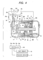
- Fig. 4 shows a linear compressor according to the third embodiment of the invention which is different from the one shown in Fig. 3 only in that a coil spring 29 is disposed between a holder 45 mounted on an inner wall of the hollow block 6 and the stator 3a of the linear motor 3 which produces a spring pressure to hold the stator 3a from being shifted left, as viewed in the drawing.
- a coil spring 29 is disposed between a holder 45 mounted on an inner wall of the hollow block 6 and the stator 3a of the linear motor 3 which produces a spring pressure to hold the stator 3a from being shifted left, as viewed in the drawing.
- Other arrangements are identical, and explanation thereof in detail will be omitted here.
- the linear motor 3 When the linear compressor of the second embodiment in Fig. 3 is turned off, the linear motor 3 may be stopped with the stator 3a being shifted left, as viewed in the drawing, away from a desired center of oscillation of the piston 5.
- the linear compressor When the linear compressor is turned on from this state, it may cause the piston 5 to pass over the top dead center and collide with the inner wall of the cylinder block 7.
- the coil spring 45 of this embodiment holds the stator 3a in a desired position (e.g., the desired center of oscillation of the piston 5) when the pressures within the back pressure chambers 28a and 28b are balanced after the linear compressor is turned off, thereby avoiding the collision of the piston 5 with the inner wall of the cylinder block 7 immediately after the linear compressor is turned on.
- an elastic member such as rubber may be used instead of the coil spring 29.
- Fig. 5 shows a linear motor 3 which may be employed in the above embodiments.
- the linear motor 3 consists essentially of a stator 3a and a rotor 3b.
- the stator 3a includes an annular inner yoke 101, an annular outer yoke 104, and a coil 106.
- the inner yoke 101 and the outer yoke 104 are secured on the hollow block 6, as shown in Fig. 1.
- the outer yoke 104 has two magnetic poles 102 and 103.
- the rotor 3b includes a cylindrical permanent magnet 107 and has the piston 5 pass through the bottom thereof.
- the outer yoke 104 includes, as shown in Fig. 6, a plurality of separate blocks 104a, 104b, 104c, and 104d whose end surfaces 114a, 114b, 114c, and 114d are glued or welded to each other.
- Each of the blocks 104a to 104d has, as shown in Figs. 7 and 9, formed in an inner wall thereof a groove 113 in which the coil 106 is fitted.
- the outer yoke 104 may be formed with at least two separate blocks.
- the coil 106 is, as shown in Fig. 8, first made by tensioning and winding wire around a bobbin 150 outward in a radial direction at high density.
- the bobbin 150 is drawn from the coil 106 and fitted into the grooves 113 of the blocks 104a to 104d of the outer yoke 104.
- the blocks 104a to 104d are glued or welded to each other to make up the outer yoke 104.
- the coil 106 may be impregnated with a resin liquid for avoiding deformation and protection thereof.
- a stator In conventional linear motors, a stator is usually made by winding wire within a groove formed in an inner wall of a one-piece annular outer yoke inward in a radial direction. It is, thus, difficult to wind the wire under high tension.
- the stator 3a of this embodiment is, as described above, made by fitting the coil 106, which is formed by winding the wire outward in the radial direction under high tension, in the grooves 113 of the blocks 104a to 104d and joining the blocks 104a to 104d to complete the outer yoke 104.
- the coil 106 of this embodiment therefore, has a higher space factor and a greater number of turns per volume as compared with the conventional linear motors. This reduces a copper loss that is proportional to the square of current flowing through the coil, thereby resulting in greatly improved efficiency of the linear motor 3.
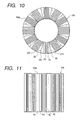
- Figs. 10, 11, and 12 show the first modification of the outer yoke 104 used in the linear motor 3.
- the outer yoke 104 of this embodiment includes twelve fan-shaped separate blocks 104a identical in size and shape with each other.
- Each of the separate blocks 104a consists of a central portion 80 and first and second outer portions 90 and 101.
- the central portion 80 is formed with quadrangular prism-shaped laminations 70 made from a material having a higher permeability.
- the first and second outer portions 90 and 101 are each formed with a triangular prism-shaped member made from, for example, resin having the permeability lower than that of the central portion 80 and the electric resistance greater than that of the central portion 80.
- Each of the blocks 104 is fabricated by sandwiching the central portion 80 between the first and second portions 90 and 101 and impregnating them with resin.
- Each of the first outer portions 90 has, as shown in Figs. 10 and 12, formed therein a circular recess or groove 210.
- Each of the second outer portions 101 has, as clearly shown in Fig. 12, formed therein a cylindrical protrusion 220.
- the assembly of the outer yoke 104 is accomplished by inserting the cylindrical protrusion 220 of each of the second outer portions 101 into the circular groove 210 of one of the first outer portion 90 from an axial direction thereof to join all the blocks 104a.
- Each of the blocks 104 may be surface-finished before the outer yoke 104 is assembled.
- the outer yoke 104 may be surface-finished after being assembled.
- the eddy current loss of a linear motor is usually proportional to the square of the thickness of a yoke, but dereased greatly in this embodiment by the formation of the central portion 80 of the outer yoke 104 with the laminations 70 having the higher permeability, which results in greatly improved efficiency of the linear motor 3.
- Each of the blocks 104 has disposed on both sides of the central portion 70 the first and second outer portions 90 and 101 each having the lower permeability and higher resistance, thereby minimizing the leakage of magnetic flux from the central portion 70 of each of the blocks 104 to adjacent one, thus resulting in a decrease in copper loss.
- the outer yoke 104 of this embodiment does not have the coil 106, but may have the same as needed.
- the inner yoke 101 shown in Fig. 5 may be fabricated in the same manner as described above.
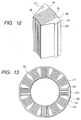
- Figs. 13, 14, and 15 show the first modification of the outer yoke 104 used in the linear motor 3.
- the outer yoke 104 of this embodiment includes twelve separate blocks 215 and an annular block retainer 216.
- Each of the blocks 215 is, as clearly shown in Fig. 14, formed with quadrangular prism-shaped laminations 217 made from a material having a higher permeability.
- the block retainer 216 as clearly shown in Fig. 15, consists of a strip member 219 and twelve C-shaped holders 218.
- the strip member 219 is flexible and made of, for example, resin which has the permeability lower than that of the blocks 215 and the resistance greater than that of the blocks 215. This avoids the flow of magnetic flux through the strip member 219 between adjacent two of the blocks 215, thereby minimizing the copper loss.
- the C-shaped holders 218 are glued on an inner surface of the strip member 219 at regular intervals and hold therein the blocks 215, as shown in Fig. 13, in a circumferential direction with regular gaps 220.
- the formation of the gaps 220 between adjacent two of the blocks 215 increases a surface area of the outer yoke 104, thereby facilitating the cooling of the linear motor 3.
- the outer yoke 104 of this embodiment does not have the coil 106, but may have the same as needed.
- the inner yoke 101 shown in Fig. 5 may be fabricated in the same manner as described above.
Landscapes
- Engineering & Computer Science (AREA)
- Power Engineering (AREA)
- Mechanical Engineering (AREA)
- General Engineering & Computer Science (AREA)
- Computer Hardware Design (AREA)
- Compressors, Vaccum Pumps And Other Relevant Systems (AREA)
- Compressor (AREA)
- Linear Motors (AREA)
- Reciprocating, Oscillating Or Vibrating Motors (AREA)
Priority Applications (2)
| Application Number | Priority Date | Filing Date | Title |
|---|---|---|---|
| EP05012750A EP1585209A2 (fr) | 1998-04-20 | 1998-11-20 | Structure améliorée de stator d'un moteur linéaire à mouvement alternatif |
| EP05012751A EP1610442A2 (fr) | 1998-04-20 | 1998-11-20 | Structure améliorée de stator d'un moteur linéaire à mouvement alternatif |
Applications Claiming Priority (5)
| Application Number | Priority Date | Filing Date | Title |
|---|---|---|---|
| JP10911098A JPH11303763A (ja) | 1998-04-20 | 1998-04-20 | 振動式圧縮機 |
| JP10911098 | 1998-04-20 | ||
| JP11047398A JPH11308846A (ja) | 1998-04-21 | 1998-04-21 | リニアモータ |
| JP11047398 | 1998-04-21 | ||
| EP98309534A EP0952347B1 (fr) | 1998-04-20 | 1998-11-20 | Dispositif de contrôle de la course de piston pour un compresseur oscillant |
Related Parent Applications (1)
| Application Number | Title | Priority Date | Filing Date |
|---|---|---|---|
| EP98309534A Division EP0952347B1 (fr) | 1998-04-20 | 1998-11-20 | Dispositif de contrôle de la course de piston pour un compresseur oscillant |
Related Child Applications (2)
| Application Number | Title | Priority Date | Filing Date |
|---|---|---|---|
| EP05012750A Division EP1585209A2 (fr) | 1998-04-20 | 1998-11-20 | Structure améliorée de stator d'un moteur linéaire à mouvement alternatif |
| EP05012751A Division EP1610442A2 (fr) | 1998-04-20 | 1998-11-20 | Structure améliorée de stator d'un moteur linéaire à mouvement alternatif |
Publications (3)
| Publication Number | Publication Date |
|---|---|
| EP1344933A2 true EP1344933A2 (fr) | 2003-09-17 |
| EP1344933A3 EP1344933A3 (fr) | 2004-05-19 |
| EP1344933B1 EP1344933B1 (fr) | 2006-01-11 |
Family
ID=26448892
Family Applications (4)
| Application Number | Title | Priority Date | Filing Date |
|---|---|---|---|
| EP05012750A Withdrawn EP1585209A2 (fr) | 1998-04-20 | 1998-11-20 | Structure améliorée de stator d'un moteur linéaire à mouvement alternatif |
| EP03013106A Expired - Lifetime EP1344933B1 (fr) | 1998-04-20 | 1998-11-20 | Structure d'entraînement d'un compresseur linéaire |
| EP05012751A Withdrawn EP1610442A2 (fr) | 1998-04-20 | 1998-11-20 | Structure améliorée de stator d'un moteur linéaire à mouvement alternatif |
| EP98309534A Expired - Lifetime EP0952347B1 (fr) | 1998-04-20 | 1998-11-20 | Dispositif de contrôle de la course de piston pour un compresseur oscillant |
Family Applications Before (1)
| Application Number | Title | Priority Date | Filing Date |
|---|---|---|---|
| EP05012750A Withdrawn EP1585209A2 (fr) | 1998-04-20 | 1998-11-20 | Structure améliorée de stator d'un moteur linéaire à mouvement alternatif |
Family Applications After (2)
| Application Number | Title | Priority Date | Filing Date |
|---|---|---|---|
| EP05012751A Withdrawn EP1610442A2 (fr) | 1998-04-20 | 1998-11-20 | Structure améliorée de stator d'un moteur linéaire à mouvement alternatif |
| EP98309534A Expired - Lifetime EP0952347B1 (fr) | 1998-04-20 | 1998-11-20 | Dispositif de contrôle de la course de piston pour un compresseur oscillant |
Country Status (8)
| Country | Link |
|---|---|
| US (2) | US6084320A (fr) |
| EP (4) | EP1585209A2 (fr) |
| KR (2) | KR100298270B1 (fr) |
| CN (3) | CN1101524C (fr) |
| DE (2) | DE69816968T9 (fr) |
| ES (1) | ES2207798T3 (fr) |
| SG (3) | SG73603A1 (fr) |
| TW (1) | TW418286B (fr) |
Cited By (3)
| Publication number | Priority date | Publication date | Assignee | Title |
|---|---|---|---|---|
| DE202005013089U1 (de) * | 2005-08-19 | 2007-01-04 | Prominent Dosiertechnik Gmbh | Magnetdosierpumpe |
| DE102005039772A1 (de) * | 2005-08-22 | 2007-03-08 | Prominent Dosiertechnik Gmbh | Magnetdosierpumpe |
| WO2007098995A1 (fr) * | 2006-02-28 | 2007-09-07 | BSH Bosch und Siemens Hausgeräte GmbH | Entrainement lineaire et compresseur lineaire a puissance adaptable |
Families Citing this family (91)
| Publication number | Priority date | Publication date | Assignee | Title |
|---|---|---|---|---|
| US6203292B1 (en) | 1997-04-20 | 2001-03-20 | Matsushita Refrigeration Company | Oscillation-type compressor |
| US6848892B1 (en) | 1997-10-15 | 2005-02-01 | Matsushita Refrigeration Company | Oscillation-type compressor |
| JP3083518B2 (ja) * | 1998-07-03 | 2000-09-04 | 三星電子株式会社 | リニア圧縮機の内側コア及びシリンダブロックの構造並びに結合方法 |
| US6664666B2 (en) * | 1998-12-23 | 2003-12-16 | Engineering Matters, Inc. | Motor assembly allowing output in multiple degrees of freedom |
| KR20010003310A (ko) * | 1999-06-22 | 2001-01-15 | 윤종용 | 리니어 압축기 |
| JP2001128434A (ja) * | 1999-10-27 | 2001-05-11 | Matsushita Refrig Co Ltd | リニアモータ |
| US6233947B1 (en) * | 1999-11-02 | 2001-05-22 | Bei Sensors & Systems, Inc. | High efficiency fuzzy logic based stirling cycle cryogenic cooler |
| BR0106730A (pt) * | 2000-02-17 | 2002-05-14 | Lg Eletronics Inc | Estrutura para estator de motor com induzido oscilante |
| US6501357B2 (en) * | 2000-03-16 | 2002-12-31 | Quizix, Inc. | Permanent magnet actuator mechanism |
| BR0001404A (pt) * | 2000-03-23 | 2001-11-13 | Brasil Compressores Sa | Sensor de posição e compressor |
| JP3512371B2 (ja) * | 2000-06-19 | 2004-03-29 | 松下電器産業株式会社 | リニア圧縮機 |
| US6520746B2 (en) * | 2000-09-27 | 2003-02-18 | Lg Electronics Inc. | Apparatus and method for controlling operation of reciprocating compressor |
| KR100367603B1 (ko) | 2000-11-20 | 2003-01-10 | 엘지전자 주식회사 | 멀티 윈도우형 리니어 모터 |
| CN1247896C (zh) * | 2000-11-29 | 2006-03-29 | Lg电子株式会社 | 控制线性压缩机的设备和方法 |
| KR100367606B1 (ko) * | 2000-11-29 | 2003-01-14 | 엘지전자 주식회사 | 벡터를 이용한 리니어 컴프레샤의 운전제어장치 |
| KR100367605B1 (ko) * | 2000-11-29 | 2003-01-14 | 엘지전자 주식회사 | 패턴인식을 이용한 리니어 컴프레샤의 운전제어장치 |
| US6537034B2 (en) * | 2000-11-29 | 2003-03-25 | Lg Electronics Inc. | Apparatus and method for controlling operation of linear compressor |
| JP3895688B2 (ja) * | 2001-03-24 | 2007-03-22 | エルジー エレクトロニクス インコーポレイティド | 往復動式圧縮機 |
| JP2002285958A (ja) * | 2001-03-28 | 2002-10-03 | Matsushita Refrig Co Ltd | リニアコンプレッサの制御装置 |
| US6623246B2 (en) * | 2001-04-13 | 2003-09-23 | Lg Electronics Inc. | Apparatus and method for controlling operation of linear motor compressor |
| KR100390787B1 (ko) * | 2001-04-19 | 2003-07-10 | 주식회사 엘지이아이 | 왕복동식 모터의 고정자 |
| JP2002349434A (ja) * | 2001-05-23 | 2002-12-04 | Matsushita Electric Ind Co Ltd | リニア圧縮機 |
| KR100408068B1 (ko) * | 2001-07-31 | 2003-12-03 | 엘지전자 주식회사 | 왕복동식 압축기의 스트로크 제어장치 및 방법 |
| KR100414098B1 (ko) * | 2001-08-01 | 2004-01-07 | 엘지전자 주식회사 | 왕복동식 압축기의 tdc 제어장치 및 방법 |
| NZ515578A (en) * | 2001-11-20 | 2004-03-26 | Fisher & Paykel Appliances Ltd | Reduction of power to free piston linear motor to reduce piston overshoot |
| KR100449009B1 (ko) * | 2001-11-27 | 2004-09-18 | 삼성전자주식회사 | 리니어 압축기 |
| CN1623068A (zh) * | 2001-12-26 | 2005-06-01 | 夏普株式会社 | 斯特林发动机 |
| KR100477111B1 (ko) * | 2002-02-01 | 2005-03-17 | 삼성전자주식회사 | 리니어 압축기 |
| US20030161735A1 (en) * | 2002-02-28 | 2003-08-28 | Samsung Electronics Co., Ltd. | Apparatus and method of controlling linear compressor |
| BR0201189B1 (pt) * | 2002-03-22 | 2010-06-29 | compressor alternativo acionado por motor linear. | |
| US6868686B2 (en) * | 2002-04-04 | 2005-03-22 | Matsushita Electric Industrial Co., Ltd. | Refrigeration cycle apparatus |
| US7184254B2 (en) * | 2002-05-24 | 2007-02-27 | Airxcel, Inc. | Apparatus and method for controlling the maximum stroke for linear compressors |
| JP2004064852A (ja) * | 2002-07-26 | 2004-02-26 | Matsushita Refrig Co Ltd | リニアモータ及びリニアモータコンプレッサ |
| BR0203724B1 (pt) * | 2002-09-12 | 2011-08-09 | bomba de fluidos e placa de transferência de fluidos e sensor indutivo para bomba de fluidos. | |
| KR100486583B1 (ko) * | 2002-10-15 | 2005-05-03 | 엘지전자 주식회사 | 왕복동식 모터의 고정자 구조 |
| US6877214B2 (en) | 2002-11-05 | 2005-04-12 | L. H. Carbide Corporation | Method of manufacturing a stack of laminations |
| CN1735749A (zh) * | 2002-11-19 | 2006-02-15 | 巴西压缩机股份有限公司 | 活塞运动的控制系统 |
| KR100499484B1 (ko) * | 2002-11-20 | 2005-07-05 | 엘지전자 주식회사 | 전자동 세탁기의 비엘디시 모터 소음 방지구조 |
| KR100511325B1 (ko) * | 2002-12-20 | 2005-08-31 | 엘지전자 주식회사 | 왕복동식 압축기를 구비한 냉동장치 |
| KR100504910B1 (ko) * | 2002-12-20 | 2005-07-29 | 엘지전자 주식회사 | 냉동 기기용 왕복동식 압축기 |
| US7005810B2 (en) | 2003-02-21 | 2006-02-28 | Matsushita Electric Industrial Co., Ltd. | Motor driving apparatus |
| KR100518012B1 (ko) * | 2003-03-11 | 2005-09-30 | 엘지전자 주식회사 | 왕복동식 모터의 고정자 조립 구조 |
| BR0301492A (pt) * | 2003-04-23 | 2004-12-07 | Brasil Compressores Sa | Sistema de ajuste de frequências de ressonância em compressor linear |
| JP3579416B1 (ja) * | 2003-06-16 | 2004-10-20 | シャープ株式会社 | リニアモータ装置およびその製造方法、リニア圧縮機ならびにスターリング機関 |
| CN1846116A (zh) * | 2003-07-01 | 2006-10-11 | 蒂艾克思股份有限公司 | 电容型位置传感器和测知方法 |
| US6914351B2 (en) | 2003-07-02 | 2005-07-05 | Tiax Llc | Linear electrical machine for electric power generation or motive drive |
| NZ527999A (en) | 2003-09-02 | 2005-08-26 | Fisher & Paykel Appliances Ltd | Controller improvements |
| US20050189824A1 (en) * | 2003-12-04 | 2005-09-01 | Lg Electronics Inc. | Reciprocating motor |
| US7456592B2 (en) * | 2003-12-17 | 2008-11-25 | Lg Electronics Inc. | Apparatus and method for controlling operation of reciprocating compressor |
| KR101002638B1 (ko) * | 2004-02-26 | 2010-12-21 | 삼성광주전자 주식회사 | 리니어 압축기 |
| DE102004010846A1 (de) * | 2004-03-05 | 2005-09-22 | BSH Bosch und Siemens Hausgeräte GmbH | Vorrichtung zur Regelung des Ankerhubs in einem reversierenden Linearantrieb |
| US7128032B2 (en) * | 2004-03-26 | 2006-10-31 | Bose Corporation | Electromagnetic actuator and control |
| US7032400B2 (en) * | 2004-03-29 | 2006-04-25 | Hussmann Corporation | Refrigeration unit having a linear compressor |
| CN100533930C (zh) * | 2004-06-09 | 2009-08-26 | 乐金电子(天津)电器有限公司 | 直线电机定子固定结构 |
| US7737598B2 (en) * | 2004-08-09 | 2010-06-15 | A. O. Smith Corporation | Electric motor having a stator |
| US7247967B2 (en) * | 2004-08-09 | 2007-07-24 | A. O. Smith Corporation | Electric motor having a stator |
| DE112004002954B4 (de) * | 2004-08-30 | 2018-06-07 | Lg Electronics Inc. | Linearkompressor |
| US20090232666A1 (en) * | 2004-08-30 | 2009-09-17 | Lg Electronics, Inc. | Linear Compressor |
| JP4084351B2 (ja) * | 2004-12-24 | 2008-04-30 | 株式会社日立製作所 | モータ一体型内接歯車式ポンプ及び電子機器 |
| US20060201175A1 (en) * | 2005-03-10 | 2006-09-14 | Hussmann Corporation | Strategic modular refrigeration system with linear compressors |
| KR100597106B1 (ko) * | 2005-04-15 | 2006-07-05 | 삼성광주전자 주식회사 | 리니어 압축기 |
| BRPI0504989A (pt) * | 2005-05-06 | 2006-12-19 | Lg Electronics Inc | aparelho e método para controlar operação de compressor de alternáncia |
| KR101234825B1 (ko) * | 2005-05-13 | 2013-02-20 | 삼성전자주식회사 | 리니어 압축기의 제어 장치 및 방법 |
| US7638913B2 (en) * | 2005-05-27 | 2009-12-29 | A.O. Smith Corporation | Rotor core with spacers |
| US7478539B2 (en) * | 2005-06-24 | 2009-01-20 | Hussmann Corporation | Two-stage linear compressor |
| US7628027B2 (en) * | 2005-07-19 | 2009-12-08 | Hussmann Corporation | Refrigeration system with mechanical subcooling |
| US7374147B2 (en) * | 2005-10-14 | 2008-05-20 | Et Us Holdings Llc | Valve assembly with overstroke device and associated method |
| US7348706B2 (en) | 2005-10-31 | 2008-03-25 | A. O. Smith Corporation | Stator assembly for an electric machine and method of manufacturing the same |
| US20070108850A1 (en) * | 2005-11-17 | 2007-05-17 | Tiax Llc | Linear electrical machine for electric power generation or motive drive |
| DE102006009229A1 (de) * | 2006-02-28 | 2007-08-30 | BSH Bosch und Siemens Hausgeräte GmbH | Linearverdichter mit carbonfaserverstärkter Feder |
| DE102006009230A1 (de) * | 2006-02-28 | 2007-08-30 | BSH Bosch und Siemens Hausgeräte GmbH | Verfahren zum Justieren eines Kolbens in einem Linearverdichter |
| US20070224058A1 (en) * | 2006-03-24 | 2007-09-27 | Ingersoll-Rand Company | Linear compressor assembly |
| ITFI20070008A1 (it) | 2007-01-17 | 2008-07-18 | Dorin Mario Spa | Motocompressore alternativo in particolare di tipo semiermetico. |
| CN101245770B (zh) * | 2007-02-17 | 2012-05-30 | 卓越剂量技术有限公司 | 电动机驱动计量泵 |
| BRPI0704947B1 (pt) * | 2007-12-28 | 2018-07-17 | Whirlpool Sa | conjunto de pistão e cilindro acionado por motor linear com sistema de reconhecimento de posição de cilindro e compressor de motor linear |
| US8702133B2 (en) * | 2008-12-02 | 2014-04-22 | Utc Fire & Security Corporation | Bi-stable actuator for electronic lock |
| DE102010064049A1 (de) * | 2010-12-23 | 2012-06-28 | Hamilton Bonaduz Ag | Pipettiervorrichtung mit Linearmotor |
| BRPI1005184B1 (pt) * | 2010-12-27 | 2020-09-24 | Embraco Indústria De Compressores E Soluções Em Refrigeração Ltda. | Mecanismo ressonante para compressores lineares |
| CA2832263C (fr) * | 2011-04-04 | 2015-12-29 | Weidmann Electrical Technology, Inc. | Ensemble capteur de force de serrage pour surveiller une degradation de transformateur |
| FR2978883B1 (fr) * | 2011-08-01 | 2013-07-26 | Moving Magnet Tech | Ensemble compact de positionnement comprenant un actionneur et un capteur integre dans la culasse de l'actionneur |
| US11466678B2 (en) | 2013-11-07 | 2022-10-11 | Gas Technology Institute | Free piston linear motor compressor and associated systems of operation |
| US10323628B2 (en) | 2013-11-07 | 2019-06-18 | Gas Technology Institute | Free piston linear motor compressor and associated systems of operation |
| DE102013019499A1 (de) * | 2013-11-21 | 2015-05-21 | Linde Aktiengesellschaft | Kolbenverdichter und Verfahren zum Verdichten eines tiefkalten, gasförmigen Mediums, insbesondere Wasserstoff |
| US10056815B2 (en) * | 2014-09-30 | 2018-08-21 | Baker Hughes, A Ge Company, Llc | Linear drive system for downhole applications |
| DE102015201466A1 (de) * | 2015-01-28 | 2016-07-28 | Robert Bosch Gmbh | Verfahren zum Betreiben und Ansteuereinrichtung für eine Kolbenpumpe |
| CN105241174B (zh) * | 2015-11-05 | 2018-02-02 | 青岛海尔股份有限公司 | 采用直线压缩机的冰箱控制方法及控制系统 |
| CN105241172B (zh) * | 2015-11-05 | 2017-12-29 | 青岛海尔股份有限公司 | 采用直线压缩机的冰箱控制方法及控制系统 |
| CN105241171B (zh) * | 2015-11-05 | 2017-12-29 | 青岛海尔股份有限公司 | 采用直线压缩机的冰箱控制方法及控制系统 |
| CN105258446B (zh) * | 2015-11-05 | 2018-08-10 | 青岛海尔股份有限公司 | 采用直线压缩机的冰箱控制方法及控制系统 |
| CN105587652B (zh) * | 2016-02-19 | 2018-07-03 | 珠海格力节能环保制冷技术研究中心有限公司 | 直线压缩机及其控制方法、装置、电器 |
| BR102018073558A2 (pt) * | 2018-11-14 | 2020-06-02 | Embraco Indústria De Compressores E Soluções Em Refrigeração Ltda | Motor linear, compressor de um equipamento de refrigeração, equipamento de refrigeração e estator aplicável em um motor linear |
Family Cites Families (18)
| Publication number | Priority date | Publication date | Assignee | Title |
|---|---|---|---|---|
| US4353220A (en) * | 1980-06-17 | 1982-10-12 | Mechanical Technology Incorporated | Resonant piston compressor having improved stroke control for load-following electric heat pumps and the like |
| FR2544926B1 (fr) * | 1983-04-20 | 1986-05-30 | Jarret Jacques | Anneau magnetique pour generateurs rectilignes a pistons libres |
| GB8311997D0 (en) * | 1983-05-03 | 1983-06-08 | Caterpillar Tractor Co | Electromagnetic machine |
| JPS60209676A (ja) * | 1984-04-02 | 1985-10-22 | Hitachi Ltd | フリ−ピストン形振動式圧縮機のピストンストロ−ク制御装置 |
| JPS61262063A (ja) * | 1985-05-14 | 1986-11-20 | Hitachi Ltd | 円筒形直動電動機 |
| US4772838A (en) * | 1986-06-20 | 1988-09-20 | North American Philips Corporation | Tri-state switching controller for reciprocating linear motors |
| US4864176A (en) * | 1988-07-29 | 1989-09-05 | Rem Technologies, Inc. | Stator support structure with stamped end plates |
| JP2651734B2 (ja) * | 1990-02-19 | 1997-09-10 | 宇宙開発事業団 | 電磁アクチュエータ |
| US5156005A (en) * | 1991-05-24 | 1992-10-20 | Sunpower, Inc. | Control of stirling cooler displacement by pulse width modulation of drive motor voltage |
| JP2742184B2 (ja) * | 1992-09-14 | 1998-04-22 | 積水化成品工業株式会社 | プラスチック回収用押出機 |
| FR2698742B1 (fr) * | 1992-11-30 | 1995-02-17 | Framatome Sa | Machine électromagnétique à induction linéaire à répartition de flux magnétique optimisée et utilisations. |
| US5300845A (en) * | 1993-04-05 | 1994-04-05 | General Electric Company | Banded electromagnetic stator core |
| JP3717961B2 (ja) * | 1995-03-14 | 2005-11-16 | 松下冷機株式会社 | 振動型圧縮機 |
| JPH09137781A (ja) * | 1995-11-15 | 1997-05-27 | Matsushita Refrig Co Ltd | 振動型圧縮機 |
| JP2790102B2 (ja) * | 1995-12-01 | 1998-08-27 | ダイキン工業株式会社 | リニアモータ式圧縮機 |
| KR0176909B1 (ko) * | 1996-05-08 | 1999-10-01 | 구자홍 | 선형 압축기 구동장치 |
| JP3568364B2 (ja) * | 1996-09-30 | 2004-09-22 | 松下電器産業株式会社 | 回転電機のコア |
| KR100301480B1 (ko) * | 1998-07-13 | 2001-09-06 | 구자홍 | 리니어 모터용 고정자 코어 및 이를 이용한 고정자 제조방법 |
-
1998
- 1998-11-06 US US09/187,005 patent/US6084320A/en not_active Expired - Fee Related
- 1998-11-12 CN CN98122329A patent/CN1101524C/zh not_active Expired - Fee Related
- 1998-11-12 CN CNB02119310XA patent/CN1187880C/zh not_active Expired - Fee Related
- 1998-11-20 KR KR1019980049914A patent/KR100298270B1/ko not_active Expired - Fee Related
- 1998-11-20 DE DE69816968T patent/DE69816968T9/de not_active Expired - Fee Related
- 1998-11-20 ES ES98309534T patent/ES2207798T3/es not_active Expired - Lifetime
- 1998-11-20 DE DE69833137T patent/DE69833137T2/de not_active Expired - Fee Related
- 1998-11-20 EP EP05012750A patent/EP1585209A2/fr not_active Withdrawn
- 1998-11-20 EP EP03013106A patent/EP1344933B1/fr not_active Expired - Lifetime
- 1998-11-20 EP EP05012751A patent/EP1610442A2/fr not_active Withdrawn
- 1998-11-20 EP EP98309534A patent/EP0952347B1/fr not_active Expired - Lifetime
- 1998-11-24 TW TW087119472A patent/TW418286B/zh active
-
1999
- 1999-01-12 SG SG1999000040A patent/SG73603A1/en unknown
- 1999-01-12 SG SG200106981A patent/SG99958A1/en unknown
- 1999-01-12 SG SG200107034A patent/SG101512A1/en unknown
-
2000
- 2000-02-23 US US09/511,785 patent/US6153951A/en not_active Expired - Fee Related
- 2000-11-11 KR KR1020000066978A patent/KR100352656B1/ko not_active Expired - Fee Related
-
2002
- 2002-05-09 CN CN02119311A patent/CN1388631A/zh active Pending
Cited By (5)
| Publication number | Priority date | Publication date | Assignee | Title |
|---|---|---|---|---|
| DE202005013089U1 (de) * | 2005-08-19 | 2007-01-04 | Prominent Dosiertechnik Gmbh | Magnetdosierpumpe |
| DE102005039772A1 (de) * | 2005-08-22 | 2007-03-08 | Prominent Dosiertechnik Gmbh | Magnetdosierpumpe |
| US8267667B2 (en) | 2005-08-22 | 2012-09-18 | Prominent Dosiertechnik Gmbh | Magnetic drive metering pump |
| WO2007098995A1 (fr) * | 2006-02-28 | 2007-09-07 | BSH Bosch und Siemens Hausgeräte GmbH | Entrainement lineaire et compresseur lineaire a puissance adaptable |
| RU2435072C2 (ru) * | 2006-02-28 | 2011-11-27 | Бсх Бош Унд Сименс Хаусгерете Гмбх | Линейный привод и линейный компрессор с изменяемой мощностью |
Also Published As
| Publication number | Publication date |
|---|---|
| DE69833137D1 (de) | 2006-04-06 |
| CN1388630A (zh) | 2003-01-01 |
| CN1187880C (zh) | 2005-02-02 |
| EP0952347A1 (fr) | 1999-10-27 |
| KR19990081787A (ko) | 1999-11-15 |
| DE69816968T9 (de) | 2004-12-16 |
| CN1101524C (zh) | 2003-02-12 |
| EP1344933A3 (fr) | 2004-05-19 |
| TW418286B (en) | 2001-01-11 |
| EP1585209A2 (fr) | 2005-10-12 |
| SG99958A1 (en) | 2003-11-27 |
| DE69833137T2 (de) | 2006-08-31 |
| KR100298270B1 (ko) | 2001-11-15 |
| SG73603A1 (en) | 2000-06-20 |
| ES2207798T3 (es) | 2004-06-01 |
| US6084320A (en) | 2000-07-04 |
| KR20010007635A (ko) | 2001-01-26 |
| SG101512A1 (en) | 2004-01-30 |
| EP1610442A2 (fr) | 2005-12-28 |
| CN1388631A (zh) | 2003-01-01 |
| DE69816968D1 (de) | 2003-09-11 |
| CN1232926A (zh) | 1999-10-27 |
| US6153951A (en) | 2000-11-28 |
| EP1344933B1 (fr) | 2006-01-11 |
| DE69816968T2 (de) | 2004-08-05 |
| KR100352656B1 (ko) | 2002-09-13 |
| EP0952347B1 (fr) | 2003-08-06 |
Similar Documents
| Publication | Publication Date | Title |
|---|---|---|
| US6084320A (en) | Structure of linear compressor | |
| KR100504319B1 (ko) | 선형압축기 | |
| EP2107671A2 (fr) | Moteur alternatif et compresseur alternatif doté de celui-ci | |
| EP2966301B1 (fr) | Compresseur linéaire et moteur linéaire | |
| US11606015B2 (en) | Linear motor and linear compressor having same | |
| US20070286751A1 (en) | Capacity control of a compressor | |
| JP4059773B2 (ja) | リニアモータおよび前記モータを含むリニアコンプレッサ | |
| JP2005344708A (ja) | 往復動圧縮機及びその駆動装置並びに制御方法 | |
| US5395218A (en) | Fluid pump apparatus | |
| US20090232666A1 (en) | Linear Compressor | |
| KR20090044890A (ko) | 왕복동식 압축기 | |
| KR200175868Y1 (ko) | 리니어압축기 | |
| JPH11132585A (ja) | 振動型圧縮機 | |
| EP2102974B1 (fr) | Moteur linéaire pour compresseur linéaire | |
| JP2522424B2 (ja) | スタ―リング冷凍機用リニアモ―タ圧縮機 | |
| KR100648787B1 (ko) | 리니어 압축기 | |
| JP2001221522A (ja) | 蓄冷式冷凍機システム用のガス圧縮機 | |
| KR0162425B1 (ko) | 리니어 압축기의 고정자 구조 | |
| KR100404116B1 (ko) | 왕복동식 압축기 | |
| KR20050115807A (ko) | 왕복동압축기 및 왕복동압축기의 구동장치 및왕복동압축기의 제어방법 | |
| JPH0427776A (ja) | スターリング冷凍機用リニアモータ圧縮機 | |
| JPH028155B2 (fr) | ||
| JP2004343911A (ja) | リニアアクチエ−タ及び冷媒圧縮機 | |
| NZ525385A (en) | Linear compressor | |
| JP2005045977A (ja) | リニアアクチエータ |
Legal Events
| Date | Code | Title | Description |
|---|---|---|---|
| PUAI | Public reference made under article 153(3) epc to a published international application that has entered the european phase |
Free format text: ORIGINAL CODE: 0009012 |
|
| AC | Divisional application: reference to earlier application |
Ref document number: 0952347 Country of ref document: EP Kind code of ref document: P |
|
| AK | Designated contracting states |
Kind code of ref document: A2 Designated state(s): DE ES FR GB IT SE |
|
| RIN1 | Information on inventor provided before grant (corrected) |
Inventor name: KOBAYASHI, MASANORI Inventor name: KATAYAMA, MAKOTO Inventor name: MORITA, ICHIRO Inventor name: INAGAKI, KOH |
|
| PUAL | Search report despatched |
Free format text: ORIGINAL CODE: 0009013 |
|
| RIC1 | Information provided on ipc code assigned before grant |
Ipc: 7F 04B 35/04 A Ipc: 7H 02K 33/10 B Ipc: 7H 02K 33/16 B Ipc: 7H 02K 33/02 B |
|
| AK | Designated contracting states |
Kind code of ref document: A3 Designated state(s): DE ES FR GB IT SE |
|
| 17P | Request for examination filed |
Effective date: 20040714 |
|
| AKX | Designation fees paid |
Designated state(s): DE ES FR GB IT |
|
| 17Q | First examination report despatched |
Effective date: 20050324 |
|
| GRAP | Despatch of communication of intention to grant a patent |
Free format text: ORIGINAL CODE: EPIDOSNIGR1 |
|
| GRAS | Grant fee paid |
Free format text: ORIGINAL CODE: EPIDOSNIGR3 |
|
| GRAA | (expected) grant |
Free format text: ORIGINAL CODE: 0009210 |
|
| AC | Divisional application: reference to earlier application |
Ref document number: 0952347 Country of ref document: EP Kind code of ref document: P |
|
| AK | Designated contracting states |
Kind code of ref document: B1 Designated state(s): DE ES FR GB IT |
|
| PG25 | Lapsed in a contracting state [announced via postgrant information from national office to epo] |
Ref country code: IT Free format text: LAPSE BECAUSE OF FAILURE TO SUBMIT A TRANSLATION OF THE DESCRIPTION OR TO PAY THE FEE WITHIN THE PRESCRIBED TIME-LIMIT;WARNING: LAPSES OF ITALIAN PATENTS WITH EFFECTIVE DATE BEFORE 2007 MAY HAVE OCCURRED AT ANY TIME BEFORE 2007. THE CORRECT EFFECTIVE DATE MAY BE DIFFERENT FROM THE ONE RECORDED. Effective date: 20060111 |
|
| REF | Corresponds to: |
Ref document number: 69833137 Country of ref document: DE Date of ref document: 20060406 Kind code of ref document: P |
|
| PG25 | Lapsed in a contracting state [announced via postgrant information from national office to epo] |
Ref country code: ES Free format text: LAPSE BECAUSE OF FAILURE TO SUBMIT A TRANSLATION OF THE DESCRIPTION OR TO PAY THE FEE WITHIN THE PRESCRIBED TIME-LIMIT Effective date: 20060422 |
|
| ET | Fr: translation filed | ||
| PLBE | No opposition filed within time limit |
Free format text: ORIGINAL CODE: 0009261 |
|
| STAA | Information on the status of an ep patent application or granted ep patent |
Free format text: STATUS: NO OPPOSITION FILED WITHIN TIME LIMIT |
|
| PGFP | Annual fee paid to national office [announced via postgrant information from national office to epo] |
Ref country code: IT Payment date: 20061130 Year of fee payment: 9 |
|
| 26N | No opposition filed |
Effective date: 20061012 |
|
| PG25 | Lapsed in a contracting state [announced via postgrant information from national office to epo] |
Ref country code: DE Free format text: LAPSE BECAUSE OF NON-PAYMENT OF DUE FEES Effective date: 20070601 |
|
| GBPC | Gb: european patent ceased through non-payment of renewal fee |
Effective date: 20061120 |
|
| REG | Reference to a national code |
Ref country code: FR Ref legal event code: ST Effective date: 20070731 |
|
| PG25 | Lapsed in a contracting state [announced via postgrant information from national office to epo] |
Ref country code: GB Free format text: LAPSE BECAUSE OF NON-PAYMENT OF DUE FEES Effective date: 20061120 |
|
| PG25 | Lapsed in a contracting state [announced via postgrant information from national office to epo] |
Ref country code: FR Free format text: LAPSE BECAUSE OF NON-PAYMENT OF DUE FEES Effective date: 20061130 |
|
| PG25 | Lapsed in a contracting state [announced via postgrant information from national office to epo] |
Ref country code: IT Free format text: LAPSE BECAUSE OF NON-PAYMENT OF DUE FEES Effective date: 20071120 |