EP1346696A2 - Clou verrouillable et appareil de visée - Google Patents
Clou verrouillable et appareil de visée Download PDFInfo
- Publication number
- EP1346696A2 EP1346696A2 EP03005280A EP03005280A EP1346696A2 EP 1346696 A2 EP1346696 A2 EP 1346696A2 EP 03005280 A EP03005280 A EP 03005280A EP 03005280 A EP03005280 A EP 03005280A EP 1346696 A2 EP1346696 A2 EP 1346696A2
- Authority
- EP
- European Patent Office
- Prior art keywords
- nail
- aiming device
- holding screw
- locking
- connecting sleeve
- Prior art date
- Legal status (The legal status is an assumption and is not a legal conclusion. Google has not performed a legal analysis and makes no representation as to the accuracy of the status listed.)
- Granted
Links
Images


Classifications
-
- A—HUMAN NECESSITIES
- A61—MEDICAL OR VETERINARY SCIENCE; HYGIENE
- A61B—DIAGNOSIS; SURGERY; IDENTIFICATION
- A61B17/00—Surgical instruments, devices or methods
- A61B17/16—Instruments for performing osteoclasis; Drills or chisels for bones; Trepans
- A61B17/17—Guides or aligning means for drills, mills, pins or wires
- A61B17/1725—Guides or aligning means for drills, mills, pins or wires for applying transverse screws or pins through intramedullary nails or pins
Definitions
- the present invention relates to a locking nail for supply of fractures of long bones.
- the invention also relates to a target device for a locking nail.
- Locking nails for treating fractures are known. Usually have locking nails cross holes at the distal end and at least one cross hole at the proximal end. Through the cross holes bone screws are passed through, which on the opposite Side are screwed into the cortex. The locking nail is secured axially and against rotation by the bone screws. With supra-condylar nails, condyle screws can also pass through the cross holes be performed.
- One problem with using locking nails is that used condition to identify the location of the cross hole to the Drill cortex in the right place from the outside. It is a series of target devices that work with X-rays to identify the location of the cross hole relative to the target device. It is therefore possible with the help of the target device and a so-called drilling or Drill the target sleeve in the right place.
- the well-known Target devices are usually firmly connected to the nail's end of impact. In this way, the position of the transverse bore can be approximated pretend.
- due to the curvature of the bone and the possible torsion of the nail when driving it in the assumed position of the cross hole is not the actual one matches.
- Target devices working with X-rays are therefore known which mechanically identify the position of the cross hole. Since the target device must be connected to the locking nail, was previously a location identification and insertion of bone screws Cross holes near the nail end not possible. The cross holes must therefore always be a minimum distance from the end of the Have locking nail.
- the invention has for its object a locking nail and to provide a target device that is reliable in the simple Are able to cross holes near the end of the locking nail Introduce bone screws or condyle screws.
- the locking nail according to the invention is at least at one of its ends with a cross hole for receiving screws, in particular Condyle screws or bone screws.
- the end is with provided with an internal thread for connection with a nail holding screw serves.
- the locking nail has means for fixing the radial position of a connector sleeve of a target device relative to the Locking nail.
- the next one at the end of the locking nail Cross hole can be a short distance from the end.
- the nailing screw of the aiming device is in the axial direction on the locking nail screwed.
- the radial determination of the target device takes place via a connector sleeve of the aiming device that is placed in on the nail retention screw the radial position, i.e. its rotational orientation relative to the locking nail is set.
- the locking nail according to the invention is therefore designed such that the target device is fixed axially and in the direction of rotation is done independently. There is already a small one for this Distance between the end of the locking nail and the one to be identified
- To determine the radial position of the connecting sleeve relative to the locking nail preferably has the distal end of the locking nail one or more recesses and / or projections on the end face.
- the task is also achieved by a target device with the Features solved from claim 4.
- the aiming device has a nail holding screw as well as a connection sleeve.
- the nail holding screw is on theirs to the locking nail pointing ends with two projecting in the axial direction Provide jaws.
- the space between the cheeks is there in a predetermined position a cross hole in the locking nail free.
- the nail holding screw is used in the aiming device according to the invention inserted so far in the bones that the farthest to the end Cross hole is not covered by the nail holding screw, but through the space between the jaws remains free.
- the nail holding screw also has an axial contact surface on the outside.
- connection sleeve of the target device is with a Provide driving means, that in the attached state of the connection sleeve interacts with the contact surface of the nail holding screw.
- the means of transport the connection sleeve lies against the contact surface in such a way that the The nail holding screw rotates together with the connection sleeve.
- the Nail holding screw is thus by turning the connection sleeve into the locking nail screwed.
- the connection sleeve is also provided with means for The connection sleeve is secured against rotation against the locking nail in the predetermined position of the nail holding screw.
- Target device according to the invention is the connecting sleeve against rotation secured against the locking nail. If the connection sleeve in the anti-rotation position is brought, so this is the nail holding screw brought into their predetermined position in which the jaws Clear the cross hole.
- the jaws of the nail holding screw are preferably threaded provided on the outside.
- the reason between the cheeks is rounded and the free ends of the cheeks are rounded.
- the nail holding screw will screwed to the distal end of the locking nail, the Clearance between the jaws releases the cross hole.
- the cheeks are shaped in such a way that a Kirschner wire inserted after drilling through the jaws when removing the nail holding screw in the hole can remain and is only pushed to the edge.
- the nail holding screw on the locking nail pointing end a circumferential projection. Between the section a circumferential groove is provided with the jaws and the projection.
- the connection sleeve has three projections on the front, the paired angles of 90 ° or 180 ° with each other and in the attached state in engage the recesses on the locking nail.
- the contact surface is preferably designed as a flat or as a groove. However, it is also conceivable to in the shaft of the nail holding screw to provide an area with several flat surfaces.
- a bore and a is preferred as a driving means of the connecting sleeve provided pin provided.
- the pin inserted in the hole extends perpendicularly and at a distance to the central longitudinal axis of the Connection sleeve. Both ends of the pin are in the inserted state in the Wall of the connection sleeve held.
- the connection sleeve is also with orientation recesses for a grip portion of the target device.
- the Handle section is preferably provided with means for fixing axially and in Direction of rotation relative to the orientation recesses. For this, the Handle section preferably a hole into which a spring-loaded pin protrudes, in one of the orientation recesses on the connection sleeve intervenes.
- the handle portion is also provided with a locking screw which in their screwed-in position the pin against the orientation recess the connecting sleeve presses.
- the nail holding screw is used to fix it in the connection sleeve in the axial direction at its end pointing away from the locking nail with a Provide threaded section, in the attached state of the connection sleeve protrudes from this.
- a nut is screwed onto the threaded section, which the Press the connection sleeve against the locking nail.
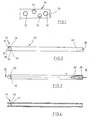
- FIG. 1 shows the distal end of a supracondylar nail 10.
- the locking nail is provided with four cross bores 12 to 18, which are used for mounting from bone screws and / or condylar screws to axial and radial Serve down the locking nail in the bone. face side the locking nail is provided with recesses, two of which are in are visible at a distance of 180 ° from one another in FIG. 1.
- the Recess 20 has a rectangular shape.
- the transverse bore 18 has a distance from the free End of the nail of 6 mm.
- An internal thread is not visible in FIG. 1, which is provided in the locking nail and from the end of the locking nail extends beyond the beginning of the transverse bore 18.
- Fig. 2 shows a nail holding screw 22. That for connection to the locking nail provided end 24 has an external thread 26 which the the above-mentioned internal thread of the locking nail corresponds.
- the End 24 has two jaws 28 and 30 which delimit a recess 32.
- the jaws 28, 30 project in the axial direction and form a U-shaped one End of the nail holding screw.
- a circumferential groove 34 is provided, which is a circumferential projection 36 follows.
- FIG. 3 shows a plan view of the flat 40. A section along the Line 4-4 of FIG. 3 is shown in FIG. 4. In the sectional view 4 is can be seen that the area 24 opposite the shaft of the nail holding screw is separated by a partition 42.
- connection sleeve 44 has a cylindrical Shaft with a first section 46 and a second section 48 which has a larger radius than the first section.
- the transition area 50 between the first and second section is conical.
- the Inner diameter of the connecting sleeve corresponds to the outer diameter of the Nail holding screw so that it slides onto the nail holding screw can be.
- the end of the first section 46 is provided with three projections 52 to 56.
- the projections 52 to 56 correspond to recesses 20 in the locking nail.
- the projections 52 to 56 are arranged in one Semicircle segment so that the projections 52 and 54 a 90 ° angle that Projections 54 and 56 also have a 90 ° angle and the projections 56 and 52 include a 180 ° angle.
- orientation recesses 58 to 62 intended.
- the orientation recesses have a funnel-shaped Area 64 with a central through hole 66.
- a through hole 68 is provided at the end of the second section 48.
- the through hole 68 is at a distance 70 from the central longitudinal axis the sleeve spaced and perpendicular to this.
- a pen 76 is pressed into the through hole and constricts it Diameter.
- the cross section of the sleeve with inserted pin corresponds to the Nail holding screw.
- FIG. 9 shows one end of a locking nail 76 with a transverse bore 78.
- the end of the locking nail is provided with an internal thread 80, as can be seen from the sectional view 10.
- the nail holding screw 22 is screwed into the locking nail with its external thread 26.
- a pin 76 is pressed into the bore 68 of the connecting sleeve 44.
- the inner diameter of the sleeve 44 is narrowed by the pin 76, as seen in Fig. 10.
- the connector sleeve 44 is pressed with the Pin 76 pushed onto the nail holding screw 22, so it is pushed on only possible if the pin 76 abuts the flat 40.
- the one screwed on Retaining sleeve 44 is on the end of the locking nail the projections 54 and 56 aligned with the recesses 80.
- a recess corresponds to each projection.
- the connecting sleeve 44 is axially secured by a nut 82 which is on the threaded section 38 of the nail holding screw is screwed on.
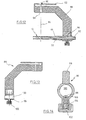
- Fig. 12 shows a cross section through the entire target device in its mounted Position.
- On the locking nail 10 is the nail holding screw 22 screwed, on which the connecting sleeve 44 is placed.
- the connection sleeve 44 is secured in the axial direction by the nut 82.
- the jaws 28, 30 the nail holding screw 22 are aligned so that the closest to the End lying cross hole along the imaginary line 84 is released.
- a grip part 86 of the Target device placed.
- the grip part 86 is axial and in the direction of rotation secured.
- the handle part 86 has a first section 88, which acts as a handle is formed and a target device 90 for a target or Has bore sleeve. By pressing the tab 92 one in the Target bore 94 inserted sleeve secured in position.
- the first section 88 is connected to a locking device via a pin connection 96 connected.
- the locking device 96 has a pin 98, via which the handle part is connected.
- the locking device 96 has a central bore 100, the inside diameter of which is the outside diameter corresponds to the sleeve in the second section. Protrudes into the bore 100 a spring-loaded pin 98, which protrudes into the bore 100 Form forms together with the funnel-shaped depressions of the Orientation recesses a snap connection.
- the pin 98 snaps into one of the marking recesses 60 to 64 on the connecting sleeve. If the pin 98 is not snapped into a marking recess, then he pressed outward against the spring tension and the locking part 96 can be moved on the connection sleeve.
- the snapped pin 98 is secured by a locking screw 102.
- the locking screw 102 has a shaft 104 which has a thread in the bore of the pin 98 is screwed in. In his screwed The position of the shaft 104 lies against the pin 98 and presses it against the Connection sleeve.
- the pin 98 is by a circumferential paragraph 106, the one with a circumferential Projection of the locking device 96 cooperates against pushed far into the opening 100 secured.
- the individual Marking recesses must be marked so that it is recognizable which of the cross holes is aimed at the target device 90. Is the target device aligned, its position is secured by the locking screw 102.
- Inserting a condyle screw into the one closest to the edge horizontal cross hole is made using a Kirschner wire, for example has a diameter of 1.8 mm.
- the Kirschner wire is inserted into a 5 mm diameter drill and the target device can be removed.
- the nail retention screw can no longer be unscrewed from the locking nail, as their Jaws are blocked by the condyle screw.
- the cheeks are rounded so that the Kirschner wire displaces in the cross hole and the nail holding screw can be unscrewed. following the condyle screw over the Kirschner wire into the cross hole inserted and screwed.
Landscapes
- Health & Medical Sciences (AREA)
- Surgery (AREA)
- Life Sciences & Earth Sciences (AREA)
- Biomedical Technology (AREA)
- Medical Informatics (AREA)
- Orthopedic Medicine & Surgery (AREA)
- Oral & Maxillofacial Surgery (AREA)
- Engineering & Computer Science (AREA)
- Dentistry (AREA)
- Heart & Thoracic Surgery (AREA)
- Nuclear Medicine, Radiotherapy & Molecular Imaging (AREA)
- Molecular Biology (AREA)
- Animal Behavior & Ethology (AREA)
- General Health & Medical Sciences (AREA)
- Public Health (AREA)
- Veterinary Medicine (AREA)
- Surgical Instruments (AREA)
- Orthopedics, Nursing, And Contraception (AREA)
Applications Claiming Priority (2)
| Application Number | Priority Date | Filing Date | Title |
|---|---|---|---|
| DE20204655U | 2002-03-21 | ||
| DE20204655U DE20204655U1 (de) | 2002-03-21 | 2002-03-21 | Verriegelungsnagel und Zielgerät |
Publications (3)
| Publication Number | Publication Date |
|---|---|
| EP1346696A2 true EP1346696A2 (fr) | 2003-09-24 |
| EP1346696A3 EP1346696A3 (fr) | 2003-11-26 |
| EP1346696B1 EP1346696B1 (fr) | 2005-10-05 |
Family
ID=7969309
Family Applications (1)
| Application Number | Title | Priority Date | Filing Date |
|---|---|---|---|
| EP03005280A Expired - Lifetime EP1346696B1 (fr) | 2002-03-21 | 2003-03-11 | Instrument de visée pour clou intramédullaire |
Country Status (5)
| Country | Link |
|---|---|
| US (1) | US7232443B2 (fr) |
| EP (1) | EP1346696B1 (fr) |
| JP (2) | JP4334896B2 (fr) |
| DE (2) | DE20204655U1 (fr) |
| ES (1) | ES2248659T3 (fr) |
Cited By (3)
| Publication number | Priority date | Publication date | Assignee | Title |
|---|---|---|---|---|
| CN100386058C (zh) * | 2006-03-07 | 2008-05-07 | 冀原 | 骨折内固定弹性应力交锁髓内钉 |
| DE102007022648B3 (de) * | 2007-05-15 | 2008-09-11 | Aesculap Ag & Co. Kg | Markraumnagel mit Zielkörper |
| EP4461238A1 (fr) | 2023-05-08 | 2024-11-13 | Stryker European Operations Limited | Dispositif médical avec mécanisme de serrage de manchon |
Families Citing this family (30)
| Publication number | Priority date | Publication date | Assignee | Title |
|---|---|---|---|---|
| US20030055316A1 (en) * | 2001-09-19 | 2003-03-20 | Brannon James Kevin | Endoscopic bone debridement |
| DE20216857U1 (de) * | 2002-11-02 | 2003-02-20 | stryker Trauma GmbH, 24232 Schönkirchen | Zielgerät für einen Verriegelungsnagel |
| DE20311718U1 (de) * | 2003-07-30 | 2004-12-09 | Stryker Trauma Gmbh | Kombination aus intramedulärem Nagel und Ziel und/oder Einschlaginstrument |
| US20050055024A1 (en) * | 2003-09-08 | 2005-03-10 | James Anthony H. | Orthopaedic implant and screw assembly |
| WO2005084560A1 (fr) * | 2004-03-01 | 2005-09-15 | Depuy International Limited | Instrument d'alignement destine a etre utilise avec un clou centromedullaire |
| US20070155271A1 (en) * | 2005-12-30 | 2007-07-05 | Touzov Igor V | Heat conductive textile and method producing thereof |
| US7727240B1 (en) | 2006-02-15 | 2010-06-01 | Blake Benton | Method and system for securing an intramedullary nail |
| JP4512902B2 (ja) * | 2006-07-13 | 2010-07-28 | 尚美 井上 | 髄内釘位置決め装置 |
| US20080154264A1 (en) * | 2006-12-22 | 2008-06-26 | Zimmer Technology, Inc. | Cannulated grooves to aid in cannula to guide quick connection |
| US7918853B2 (en) * | 2007-03-20 | 2011-04-05 | Smith & Nephew, Inc. | Orthopaedic plate and screw assembly |
| US8784430B2 (en) * | 2007-04-26 | 2014-07-22 | Zimmer, Inc. | Nail cap cannula |
| EP2166973B1 (fr) | 2007-05-25 | 2016-03-16 | Zimmer GmbH | Clou intramédullaire renforcé |
| DE202008000914U1 (de) * | 2008-01-22 | 2008-03-20 | Stryker Trauma Gmbh | Kirschnerdraht-Klammer |
| US9629806B2 (en) * | 2008-07-21 | 2017-04-25 | Si Group, Inc. | High content sodium ibuprofen granules, their preparation and their use in preparing non-effervescent solid dosage forms |
| WO2010045116A1 (fr) * | 2008-10-14 | 2010-04-22 | Zimmer, Inc. | Clou intra-médullaire modulaire |
| ES2524076T3 (es) | 2008-10-15 | 2014-12-04 | Zimmer Gmbh | Clavo intramedular |
| USD611225S1 (en) * | 2009-01-02 | 2010-03-02 | Medshape Solutions, Inc. | Intramedullary medical device |
| WO2010123879A1 (fr) * | 2009-04-20 | 2010-10-28 | Virginia Tech Intellectual Properties, Inc. | Dispositif de ciblage de clou intramédullaire |
| CN105726112B (zh) | 2009-06-30 | 2021-04-27 | 史密夫和内修有限公司 | 整形外科的植入物和紧固组件 |
| US8449544B2 (en) | 2009-06-30 | 2013-05-28 | Smith & Nephew, Inc. | Orthopaedic implant and fastener assembly |
| CA2783553C (fr) | 2009-12-11 | 2017-10-17 | Small Bone Innovations, Inc. | Dispositif de fusion de cheville, instrumentation et procedes afferents |
| CN103025252B (zh) | 2010-07-23 | 2017-02-15 | 新特斯有限责任公司 | 保护套管保持机构 |
| EP2755580B1 (fr) | 2011-09-16 | 2016-06-22 | Stryker European Holdings I, LLC | Configuration de trou de verrouillage pour clou intramédullaire |
| DE202012103384U1 (de) | 2012-09-05 | 2012-09-24 | Signus Medizintechnik Gmbh | Beckenringimplantat |
| CN106714708B (zh) * | 2014-07-15 | 2020-12-01 | Ot医疗技术有限公司 | 用于在管状骨内固定标记钉的定位设备 |
| US10357314B2 (en) | 2015-07-08 | 2019-07-23 | Stryker European Holdings I, Llc | Instrumentation and method for repair of a bone fracture |
| CN109745115A (zh) * | 2019-02-21 | 2019-05-14 | 江苏双羊医疗器械有限公司 | 一种骨科微创上钉器 |
| CN116133605A (zh) | 2020-05-29 | 2023-05-16 | 史赛克欧洲运营有限公司 | 用于髓内钉的漏斗孔 |
| US11291488B1 (en) | 2021-02-24 | 2022-04-05 | Medshape, Inc. | Dynamic compression devices and processes for making and using same |
| US12527606B1 (en) | 2021-08-26 | 2026-01-20 | Medshape, Inc. | System and method for bone fixation based on bone quality |
Family Cites Families (18)
| Publication number | Priority date | Publication date | Assignee | Title |
|---|---|---|---|---|
| US5312406A (en) | 1986-12-30 | 1994-05-17 | Smith & Nephew Richards Inc. | Method of treating an intertrochanteric fracture |
| US5176681A (en) | 1987-12-14 | 1993-01-05 | Howmedica International Inc. | Intramedullary intertrochanteric fracture fixation appliance and fitting device |
| DE9101037U1 (de) | 1991-01-30 | 1991-04-18 | Howmedica GmbH, 2314 Schönkirchen | Zielgerät für ein Implantat zur Versorgung trochanterer und subtrochanterer Frakturen |
| DE9115200U1 (de) * | 1991-12-07 | 1992-02-13 | Howmedica GmbH, 2314 Schönkirchen | Verriegelungsnagel für die Versorgung von Frakturen der Röhrenknochen |
| US5352227A (en) * | 1993-02-03 | 1994-10-04 | Howmedica Inc. | Intercalary device |
| US5489284A (en) * | 1994-07-15 | 1996-02-06 | Smith & Nephew Richards Inc. | Cannulated modular intramedullary nail |
| US5855579A (en) * | 1994-07-15 | 1999-01-05 | Smith & Nephew, Inc. | Cannulated modular intramedullary nail |
| US5620445A (en) * | 1994-07-15 | 1997-04-15 | Brosnahan; Robert | Modular intramedullary nail |
| US5766174A (en) | 1995-09-26 | 1998-06-16 | Orthologic Corporation | Intramedullary bone fixation device |
| IT1293934B1 (it) | 1997-01-21 | 1999-03-11 | Orthofix Srl | Chiodo endomidollare per il trattamento delle fratture dell'anca |
| US5766179A (en) * | 1997-03-05 | 1998-06-16 | Orthofix S.R.L. | Mechanical system for blind nail-hole alignment of bone screws |
| IT1296954B1 (it) * | 1997-12-11 | 1999-08-03 | Ortomedical S P A | Chiodo endomidollare per uso in osteosintesi per il trattamento chirurgico delle fratture diafisometafisarie di femore e di tibia, |
| AT2708U1 (de) | 1998-01-19 | 1999-03-25 | Habernek Hans Dr | Universalimplantatsystem bestehend aus einem universell anwendbaren marknagel mit zugehörigem zielgerät |
| DE29806564U1 (de) | 1998-04-09 | 1999-08-12 | Howmedica Gmbh | Zielgerät für einen Verriegelungsnagel |
| DE50015249D1 (de) * | 1999-05-12 | 2008-08-21 | Zimmer Gmbh | Verriegelungsnagel zur Versorgung von Femurschaftfrakturen |
| EP1090596B1 (fr) * | 1999-08-30 | 2006-07-05 | Zimmer GmbH | Clou intramédullaire pour l'humerus |
| US6629976B1 (en) | 1999-11-01 | 2003-10-07 | Sulzer Orthopedics, Ltd. | Radius marrow nail |
| EP1095626B1 (fr) | 1999-11-01 | 2016-02-24 | Zimmer GmbH | Clou centromédullaire pour le radius |
-
2002
- 2002-03-21 DE DE20204655U patent/DE20204655U1/de not_active Expired - Lifetime
-
2003
- 2003-03-11 DE DE50301281T patent/DE50301281D1/de not_active Expired - Lifetime
- 2003-03-11 ES ES03005280T patent/ES2248659T3/es not_active Expired - Lifetime
- 2003-03-11 EP EP03005280A patent/EP1346696B1/fr not_active Expired - Lifetime
- 2003-03-19 US US10/391,896 patent/US7232443B2/en not_active Expired - Lifetime
- 2003-03-24 JP JP2003079786A patent/JP4334896B2/ja not_active Expired - Fee Related
-
2009
- 2009-03-05 JP JP2009051889A patent/JP2009142675A/ja not_active Ceased
Non-Patent Citations (1)
| Title |
|---|
| None |
Cited By (3)
| Publication number | Priority date | Publication date | Assignee | Title |
|---|---|---|---|---|
| CN100386058C (zh) * | 2006-03-07 | 2008-05-07 | 冀原 | 骨折内固定弹性应力交锁髓内钉 |
| DE102007022648B3 (de) * | 2007-05-15 | 2008-09-11 | Aesculap Ag & Co. Kg | Markraumnagel mit Zielkörper |
| EP4461238A1 (fr) | 2023-05-08 | 2024-11-13 | Stryker European Operations Limited | Dispositif médical avec mécanisme de serrage de manchon |
Also Published As
| Publication number | Publication date |
|---|---|
| JP2009142675A (ja) | 2009-07-02 |
| EP1346696A3 (fr) | 2003-11-26 |
| US20040010252A1 (en) | 2004-01-15 |
| JP2003275219A (ja) | 2003-09-30 |
| US7232443B2 (en) | 2007-06-19 |
| DE20204655U1 (de) | 2002-06-13 |
| ES2248659T3 (es) | 2006-03-16 |
| DE50301281D1 (de) | 2006-02-16 |
| JP4334896B2 (ja) | 2009-09-30 |
| EP1346696B1 (fr) | 2005-10-05 |
Similar Documents
| Publication | Publication Date | Title |
|---|---|---|
| EP1346696B1 (fr) | Instrument de visée pour clou intramédullaire | |
| EP1175871B1 (fr) | Clou de verrouillage | |
| DE60119890T2 (de) | Handfixierungsvorrichtung | |
| DE69211561T2 (de) | Vorrichtung zum Einsetzen eines Implants | |
| DE19518530B4 (de) | Instrument zum Einsetzen und Befestigen eines intramedullären Nagels | |
| DE69930867T2 (de) | Fixierungsgerät | |
| DE602004000199T2 (de) | Ellenbogengelenkprothese | |
| EP1415599B1 (fr) | Appareil de visée pour clou intramédullaire | |
| DE60204034T2 (de) | Knochenfixationssystem | |
| DE69124293T2 (de) | Vorrichtung zur Behandlung von Wirbelsäulenerkrankungen | |
| DE60201120T2 (de) | Vorrichtung zur Auffindung der Position von Schraubenlöchern zur Fixierung eines Markraumnagels | |
| DE69529479T2 (de) | Führungsinstrument | |
| DE9115200U1 (de) | Verriegelungsnagel für die Versorgung von Frakturen der Röhrenknochen | |
| DE3504565A1 (de) | Aeusserlich einsetzbarer gelenkartiger minifixator | |
| EP1372502A1 (fr) | Element d'ancrage | |
| EP1440664A2 (fr) | Implant pour l'ostéosynthèse | |
| EP2152173A2 (fr) | Clou centromédullaire, en particulier clou centromédullaire verrouillé, et dispositif pour fixer ce clou centromédullaire dans un os long | |
| CH661860A5 (de) | Vorrichtung zur externen fixierung von knochenfragmenten. | |
| DE19713416A1 (de) | Führungsvorrichtung für ein Zwischenwirbelimplantat | |
| DE19534136A1 (de) | Externer oder interner Fixateur zur Wiederherstellung von Brüchen oder Arthroplastiken des Skeletts | |
| DE102014109935B4 (de) | Positioniervorrichtung zum Fixieren eines Marknagels in einem Röhrenknochen | |
| EP1354562B1 (fr) | Système d' ostéosynthèse | |
| CH624570A5 (en) | Medullary pin and targeting device for anchoring it in the medullary canal | |
| DE19852945B4 (de) | Knochennagel für die intramedulläre Kompressionsnagelung von Femurfrakturen | |
| EP1269929A1 (fr) | Système de liaison destiné à l'arthrodese de la region lombaire de la colonne vertébrale |
Legal Events
| Date | Code | Title | Description |
|---|---|---|---|
| PUAI | Public reference made under article 153(3) epc to a published international application that has entered the european phase |
Free format text: ORIGINAL CODE: 0009012 |
|
| AK | Designated contracting states |
Kind code of ref document: A2 Designated state(s): AT BE BG CH CY CZ DE DK EE ES FI FR GB GR HU IE IT LI LU MC NL PT SE SI SK TR |
|
| AX | Request for extension of the european patent |
Extension state: AL LT LV MK RO |
|
| PUAL | Search report despatched |
Free format text: ORIGINAL CODE: 0009013 |
|
| AK | Designated contracting states |
Kind code of ref document: A3 Designated state(s): AT BE BG CH CY CZ DE DK EE ES FI FR GB GR HU IE IT LI LU MC NL PT SE SI SK TR |
|
| AX | Request for extension of the european patent |
Extension state: AL LT LV MK RO |
|
| 17P | Request for examination filed |
Effective date: 20040103 |
|
| 17Q | First examination report despatched |
Effective date: 20040218 |
|
| AKX | Designation fees paid |
Designated state(s): CH DE ES FR GB IT LI |
|
| GRAP | Despatch of communication of intention to grant a patent |
Free format text: ORIGINAL CODE: EPIDOSNIGR1 |
|
| GRAS | Grant fee paid |
Free format text: ORIGINAL CODE: EPIDOSNIGR3 |
|
| RTI1 | Title (correction) |
Free format text: AIMING GUIDE FOR USE WITH INTRAMEDULLARY NAIL |
|
| GRAA | (expected) grant |
Free format text: ORIGINAL CODE: 0009210 |
|
| AK | Designated contracting states |
Kind code of ref document: B1 Designated state(s): CH DE ES FR GB IT LI |
|
| REG | Reference to a national code |
Ref country code: GB Ref legal event code: FG4D Free format text: NOT ENGLISH |
|
| REG | Reference to a national code |
Ref country code: CH Ref legal event code: EP Ref country code: CH Ref legal event code: NV Representative=s name: ISLER & PEDRAZZINI AG |
|
| GBT | Gb: translation of ep patent filed (gb section 77(6)(a)/1977) | ||
| REF | Corresponds to: |
Ref document number: 50301281 Country of ref document: DE Date of ref document: 20060216 Kind code of ref document: P |
|
| REG | Reference to a national code |
Ref country code: ES Ref legal event code: FG2A Ref document number: 2248659 Country of ref document: ES Kind code of ref document: T3 |
|
| ET | Fr: translation filed | ||
| PLBE | No opposition filed within time limit |
Free format text: ORIGINAL CODE: 0009261 |
|
| STAA | Information on the status of an ep patent application or granted ep patent |
Free format text: STATUS: NO OPPOSITION FILED WITHIN TIME LIMIT |
|
| 26N | No opposition filed |
Effective date: 20060706 |
|
| REG | Reference to a national code |
Ref country code: CH Ref legal event code: PCAR Free format text: ISLER & PEDRAZZINI AG;POSTFACH 1772;8027 ZUERICH (CH) |
|
| REG | Reference to a national code |
Ref country code: FR Ref legal event code: PLFP Year of fee payment: 14 |
|
| REG | Reference to a national code |
Ref country code: CH Ref legal event code: PUE Owner name: STRYKER EUROPEAN HOLDINGS VI, LLC, US Free format text: FORMER OWNER: STRYKER TRAUMA GMBH, DE Ref country code: CH Ref legal event code: PUE Owner name: STRYKER EUROPEAN HOLDINGS I, LLC, US Free format text: FORMER OWNER: STRYKER EUROPEAN HOLDINGS VI, LLC, US |
|
| REG | Reference to a national code |
Ref country code: DE Ref legal event code: R081 Ref document number: 50301281 Country of ref document: DE Owner name: STRYKER EUROPEAN OPERATIONS HOLDINGS LLC, KALA, US Free format text: FORMER OWNER: STRYKER EUROPEAN HOLDINGS VI, LLC (N.D. GES. D. STAATES DELAWARE), KALAMAZOO, MICH., US Ref country code: DE Ref legal event code: R081 Ref document number: 50301281 Country of ref document: DE Owner name: STRYKER EUROPEAN OPERATIONS HOLDINGS LLC, KALA, US Free format text: FORMER OWNER: STRYKER TRAUMA GMBH, 24232 SCHOENKIRCHEN, DE Ref country code: DE Ref legal event code: R081 Ref document number: 50301281 Country of ref document: DE Owner name: STRYKER EUROPEAN HOLDINGS I, LLC (N.D. GES. D., US Free format text: FORMER OWNER: STRYKER EUROPEAN HOLDINGS VI, LLC (N.D. GES. D. STAATES DELAWARE), KALAMAZOO, MICH., US Ref country code: DE Ref legal event code: R081 Ref document number: 50301281 Country of ref document: DE Owner name: STRYKER EUROPEAN HOLDINGS I, LLC (N.D. GES. D., US Free format text: FORMER OWNER: STRYKER TRAUMA GMBH, 24232 SCHOENKIRCHEN, DE |
|
| REG | Reference to a national code |
Ref country code: ES Ref legal event code: PC2A Owner name: STRYKER EUROPEAN HOLDINGS I,LLC Effective date: 20161013 |
|
| REG | Reference to a national code |
Ref country code: GB Ref legal event code: 732E Free format text: REGISTERED BETWEEN 20161006 AND 20161012 |
|
| REG | Reference to a national code |
Ref country code: GB Ref legal event code: 732E Free format text: REGISTERED BETWEEN 20161013 AND 20161019 |
|
| REG | Reference to a national code |
Ref country code: FR Ref legal event code: TP Owner name: STRYKER EUROPEAN HOLDINGS I, LLC, US Effective date: 20161108 |
|
| REG | Reference to a national code |
Ref country code: FR Ref legal event code: PLFP Year of fee payment: 15 |
|
| REG | Reference to a national code |
Ref country code: FR Ref legal event code: PLFP Year of fee payment: 16 |
|
| PGFP | Annual fee paid to national office [announced via postgrant information from national office to epo] |
Ref country code: GB Payment date: 20200304 Year of fee payment: 18 Ref country code: IT Payment date: 20200221 Year of fee payment: 18 |
|
| PGFP | Annual fee paid to national office [announced via postgrant information from national office to epo] |
Ref country code: CH Payment date: 20200313 Year of fee payment: 18 |
|
| PGFP | Annual fee paid to national office [announced via postgrant information from national office to epo] |
Ref country code: FR Payment date: 20200214 Year of fee payment: 18 |
|
| PGFP | Annual fee paid to national office [announced via postgrant information from national office to epo] |
Ref country code: ES Payment date: 20200401 Year of fee payment: 18 |
|
| REG | Reference to a national code |
Ref country code: CH Ref legal event code: PUE Owner name: STRYKER EUROPEANS OPERATIONS HOLDINGS LLC, US Free format text: FORMER OWNER: STRYKER EUROPEAN HOLDINGS I, LLC, US |
|
| REG | Reference to a national code |
Ref country code: CH Ref legal event code: PK Free format text: BERICHTIGUNG INHABER |
|
| REG | Reference to a national code |
Ref country code: DE Ref legal event code: R081 Ref document number: 50301281 Country of ref document: DE Owner name: STRYKER EUROPEAN OPERATIONS HOLDINGS LLC, KALA, US Free format text: FORMER OWNER: STRYKER EUROPEAN HOLDINGS I, LLC (N.D. GES. D. STAATES DELAWARE), KALAMAZOO, MICH., US |
|
| REG | Reference to a national code |
Ref country code: GB Ref legal event code: 732E Free format text: REGISTERED BETWEEN 20210408 AND 20210414 |
|
| PGFP | Annual fee paid to national office [announced via postgrant information from national office to epo] |
Ref country code: DE Payment date: 20210224 Year of fee payment: 19 |
|
| REG | Reference to a national code |
Ref country code: CH Ref legal event code: PL |
|
| GBPC | Gb: european patent ceased through non-payment of renewal fee |
Effective date: 20210311 |
|
| PG25 | Lapsed in a contracting state [announced via postgrant information from national office to epo] |
Ref country code: FR Free format text: LAPSE BECAUSE OF NON-PAYMENT OF DUE FEES Effective date: 20210331 Ref country code: GB Free format text: LAPSE BECAUSE OF NON-PAYMENT OF DUE FEES Effective date: 20210311 Ref country code: CH Free format text: LAPSE BECAUSE OF NON-PAYMENT OF DUE FEES Effective date: 20210331 Ref country code: LI Free format text: LAPSE BECAUSE OF NON-PAYMENT OF DUE FEES Effective date: 20210331 |
|
| PG25 | Lapsed in a contracting state [announced via postgrant information from national office to epo] |
Ref country code: IT Free format text: LAPSE BECAUSE OF NON-PAYMENT OF DUE FEES Effective date: 20210311 |
|
| REG | Reference to a national code |
Ref country code: ES Ref legal event code: FD2A Effective date: 20220523 |
|
| PG25 | Lapsed in a contracting state [announced via postgrant information from national office to epo] |
Ref country code: ES Free format text: LAPSE BECAUSE OF NON-PAYMENT OF DUE FEES Effective date: 20210312 |
|
| REG | Reference to a national code |
Ref country code: DE Ref legal event code: R119 Ref document number: 50301281 Country of ref document: DE |
|
| PG25 | Lapsed in a contracting state [announced via postgrant information from national office to epo] |
Ref country code: DE Free format text: LAPSE BECAUSE OF NON-PAYMENT OF DUE FEES Effective date: 20221001 |