EP1348621B1 - Fensterbefestigungssystem und Methode zur Fensterbefestigung - Google Patents
Fensterbefestigungssystem und Methode zur Fensterbefestigung Download PDFInfo
- Publication number
- EP1348621B1 EP1348621B1 EP03075854A EP03075854A EP1348621B1 EP 1348621 B1 EP1348621 B1 EP 1348621B1 EP 03075854 A EP03075854 A EP 03075854A EP 03075854 A EP03075854 A EP 03075854A EP 1348621 B1 EP1348621 B1 EP 1348621B1
- Authority
- EP
- European Patent Office
- Prior art keywords
- window frame
- engaging
- engaging mechanism
- teeth
- sidewall
- Prior art date
- Legal status (The legal status is an assumption and is not a legal conclusion. Google has not performed a legal analysis and makes no representation as to the accuracy of the status listed.)
- Expired - Lifetime
Links
- 238000000034 method Methods 0.000 title claims description 7
- 230000007246 mechanism Effects 0.000 claims description 48
- 230000008878 coupling Effects 0.000 claims description 6
- 238000010168 coupling process Methods 0.000 claims description 6
- 238000005859 coupling reaction Methods 0.000 claims description 6
- 230000000712 assembly Effects 0.000 description 18
- 238000000429 assembly Methods 0.000 description 18
- 238000009434 installation Methods 0.000 description 7
- 239000000853 adhesive Substances 0.000 description 6
- 230000001070 adhesive effect Effects 0.000 description 6
- 238000012423 maintenance Methods 0.000 description 6
- -1 for example Substances 0.000 description 2
- 239000000463 material Substances 0.000 description 2
- RTAQQCXQSZGOHL-UHFFFAOYSA-N Titanium Chemical compound [Ti] RTAQQCXQSZGOHL-UHFFFAOYSA-N 0.000 description 1
- 238000004140 cleaning Methods 0.000 description 1
- 239000000446 fuel Substances 0.000 description 1
- 229920001169 thermoplastic Polymers 0.000 description 1
- 239000004416 thermosoftening plastic Substances 0.000 description 1
- 229910052719 titanium Inorganic materials 0.000 description 1
- 239000010936 titanium Substances 0.000 description 1
Images


Classifications
-
- B—PERFORMING OPERATIONS; TRANSPORTING
- B64—AIRCRAFT; AVIATION; COSMONAUTICS
- B64C—AEROPLANES; HELICOPTERS
- B64C1/00—Fuselages; Constructional features common to fuselages, wings, stabilising surfaces or the like
- B64C1/14—Windows; Doors; Hatch covers or access panels; Surrounding frame structures; Canopies; Windscreens accessories therefor, e.g. pressure sensors, water deflectors, hinges, seals, handles, latches, windscreen wipers
- B64C1/1476—Canopies; Windscreens or similar transparent elements
- B64C1/1492—Structure and mounting of the transparent elements in the window or windscreen
Definitions
- This invention relates generally to an aircraft window assembly, and more particularly to a window attachment system and a method for installing the assembly to a sidewall panel of an aircraft.
- a typical window assembly includes a multi-frame window assembly attachable and affixable to the aircraft sidewall.
- the most common of these assemblies require the combination of hardware fastener mechanisms, typically brackets, and adhesives to affix the window assembly to an aircraft's fixed outer sidewall.
- the brackets are affixed, via the adhesive, to the sidewall.
- the window assemblies are then affixed to the brackets.
- the window assemblies are affixed to the sidewall using both mechanical affixing and adhesive affixing.
- the installation of the brackets is very labor intensive and time consuming.
- brackets are very pliable and weak and are subject to increased maintenance and replacement costs.
- brackets Yet another problem with current designs is an inability to consistently and uniformly attach the brackets on the aircraft sidewall. This is because the brackets cannot be exactly placed when affixed with adhesives. This leads to increased assembly costs because installers must take more time to affix and adjust the brackets.
- US-A-6,082,674 discloses an aircraft window escutcheon assembly including front and back panels having aligned window openings. Also fasteners are disclosed which snap into receptacles on the sidewall. Also the use of the formal hooks and bosses is disclosed.
- US-B-6,227,491 also discloses use of snap fastenings for a window unit for aircraft cabins.
- US-A-2,722,170 discloses an arrangement for supporting a ventilating grill wherein a sidewall is provided with teeth to accommodate fingers attached to the grill.
- the present invention provides an aircraft window assembly with a readily attachable window assembly for efficient and easy installation and maintenance of aircraft windows.
- the aircraft has a sidewall having an inner perimeter that defines an opening.
- the window assembly includes an outer window frame.
- a center window frame is attached to the outer window frame, and an inner window frame is attached to the center window frame.
- the inner window frame is readily attachable to the sidewall adjacent to opening of the inner perimeter.
- the inner window frame includes a releasable coupling mechanism that includes first and second engaging mechanisms.
- the first and second engaging mechanisms each include a flange with one or more teeth to engage one another when torque is applied through one of several pinholes on the periphery of the inner window frame via a torsion spring assembly.
- the window assembly is disengaged by disengaging the first and second engaging mechanisms via a disengagement tab.
- the present invention permits aircraft window assemblies to be installed without use of unnecessary adhesion or special tools.
- window assemblies can be installed in less time and with reduced costs.
- window assembly installation can be standardized, and maintenance of installed window assemblies is reduced.
- the present invention provides a window assembly and a method for installing the assembly to a sidewall panel of an aircraft.
- FIGURE 1 depicts a section of an aircraft cabin sidewall 1 with a cabin side view of a pair of window assemblies 3 according to the present invention.
- an inner perimeter 7 of an outer sidewall 5 of the aircraft cabin sidewall 1 serves as the structure for defining an opening 9 for the window assemblies 3.
- FIGURE 2 depicts a section view of an outer sidewall 5 opposite an aircraft cabin sidewall 1 view of a pair of window assemblies 3 according to the present invention.
- the outer sidewall 5 includes the inner perimeter 7 defining the opening 9.
- the opening 9 serves to index a location for the installation of the window assembly 3.
- the window assembly 3 includes a coupled inner window frame 11, center window frame 13 and outer window frame 15. The coupling of the inner, center and outer window frame 11, 13, and 15, is well known in the art, and a description is not necessary for an understanding of the invention.
- the window assembly 3 further includes a sun-shade guide tract 17.
- the window assembly is coupled to the outer sidewall 5 in the indexed location of the opening 9 via a first engaging mechanism 25 and second engaging mechanism 35 as is further illustrated in FIGURES 3 and 4.
- the first and second engaging mechanisms 25 and 35 facilitate the coupling and decoupling of the window assembly 3 from the opening 9 in the outer sidewall 5 without having to remove the outer sidewall 5 to access the window assembly 3.
- FIGURE 3 depicts a view in the direction of an aircraft cabin of a lower portion of a readily attachable window assembly 3 coupled to an aircraft outer sidewall 5.
- the inner window frame 11 of the window assembly 3 is formed with longitudinal protrusions along the engageable lower edge periphery which include one or more elastically deformable hooks 21 and bosses 23.
- the hooks 21 and bosses 23 provide attachment functionality and location indexing between the inner window frame 11 and the first engaging mechanism 25.
- the hooks 21 and bosses 23 are molded of the same material, for example, thermoplastics, as the base part of the inner window frame 11.
- the hooks 21 and bosses 23 are formed of other material, for example, titanium, and attached independently to the inner window frame 11.
- the first engaging mechanism 25 includes two engaging flanges 27, 29 each formed with independently rotatable hooked arms 31 and toothed engaging assemblies 33.
- Each engaging flange 27, 29 is shaped to be assembled into the deformable hooks 21 and bosses 23 associated with the inner window frame 11 of the window assembly 3 so that each engaging flange 27, 29 is independently engageable to the second engaging mechanism 35.
- the rotatable hooked arms include a locking boss 45 which engages the inner perimeter 7 of the sidewall 5.
- the second engaging mechanism 35 includes a rotatable toothed engaging assembly 39.
- the second engaging mechanism 35 further includes a torsion spring assembly 41.
- the torsion spring assembly includes the torsion spring 43 set over a spring supporting rod 45 and placed center to the first and second engaging mechanisms 25 and 35.
- the torsion spring assembly 41 provides a force tension to engage the first and second engaging mechanisms 25 and 35, in a locked position relative to the torque created by the torque applied to each independently rotatable hooked arm 31 and toothed engaging assemblies 33, 39.
- the hooked arms 31 are independently rotated into the engaged position by accessing one or more pin holes 47 with a pin tool along the perimeter of the inner window frame 11. The position of the inner window frame 11 is adjusted by applying an appropriate amount of torque to the hooked arms 31 via the pin tool.
- the toothed assemblies 33, 39 click against each other.
- the teeth of the toothed assemblies 33, 39 are designed to allow rotation in one direction, but not the other direction. This allows the window assembly 3 to be continuously tightened against the sidewall periphery without the rotatable hooked arms 31 from unexpectedly releasing torque in the opposite direction unless the toothed assemblies 33, 39 have been manually disengaged as described below.
- the second engaging mechanism 35 further includes a disengagement tab 49 for releasably disengaging the engaged toothed engaging assemblies 33, 39 of the first and the second engaging mechanisms 25 and 35 thus allowing the window assembly 3 to be decoupled from the aircraft sidewall 5.
- an installer angles the window assembly 3 so that top of the window assembly 3 is angled toward the aircraft sidewall 5.
- the installer slides the upper portion of the window assembly 3 up and into the sidewall opening 9 until the bonded tabs (not shown) on the sidewall 5 are inserted into the pockets (not shown) located on the top of the window assembly 3.
- the window assembly 3 is now installed to the top portion of the opening 9 with the first and second engaging mechanisms 25 and 35 still unengaged and therefore not coupled to the sidewall 5.
- the lower edge of the window assembly 3 is pushed straight in toward the sidewall 5.
- the window assembly 3 is now in the final position. However, the window assembly 3 is not locked in place.
- the installer accesses the pin hole 47 and uses a pin tool to engage each independent rotatable hooked arm 31 until it can be rotated no further.
- the window assembly 3 is now coupled to the aircraft sidewall 5.
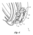
- FIGURE 4 depicts a view in the direction of an aircraft cabin of a lower portion of a readily attachable window assembly 3 in a disengaged position decoupled from an aircraft sidewall 5.
- FIGURE 3 illustrates, the first engaging mechanism 25 and the second engaging mechanism 35 are engaged, thus coupling the window assembly 3 to the aircraft sidewall 5.
- the disengagement tab 49 is accessed with a "skin" tool, or putty knife. This tool is slid between the lower center portion of the inner window frame 11 and the sidewall 5 until the tool comes into contact with the tab (not visible) of the disengagement tab 49.
Landscapes
- Engineering & Computer Science (AREA)
- Mechanical Engineering (AREA)
- Aviation & Aerospace Engineering (AREA)
- Window Of Vehicle (AREA)
- Securing Of Glass Panes Or The Like (AREA)
- Connection Of Plates (AREA)
- Hinges (AREA)
Claims (6)
- Lösbare Fensteranordnung (3) zur Befestigung an einer in einer Seitenwand eines Flugzeugs definierten Öffnung mit einem Innenumfang (7), wobei die Anordnung umfasst:einen äußeren Fensterrahmen (15);einen mittleren Fensterrahmen (13), welcher an dem äußeren Fensterrahmen (15) angebracht ist; undeinen inneren Fensterrahmen (11), welcher an dem mittleren Fensterrahmen (13) angebracht ist und welcher lösbar an der Seitenwand anbringbar ist, wobei der innere Fensterrahmen mindestens einen verformbaren Haken (21) und Vorsprung (23) aufweist;einen lösbaren Koppelmechanismus, welcher an dem inneren Fensterrahmen (11) angebrachte erste und zweite Eingreifmechanismen (25, 35) aufweist, wobei der erste Eingreifmechanismus (25) mittels des Hakens (21) und des Vorsprungs (23) an dem inneren Fensterrahmen (11) angebracht ist und mindestens einen Flansch (27, 29) mit einer ersten Vielzahl von Zähnen (33) aufweist,wobei der erste Eingreifmechanismus (25) ferner mit mindestens einem drehbaren hakenförmigen Arm (31) ausgebildet ist, welcher einen Verriegelungsvorsprung (45), der in die Seitenwand eingreift, aufweist, wenn der erste Eingreifmechanismus (25) in Position gedreht wird, undwobei der zweite Eingreifmechanismus (35) einen zweiten Flansch mit einem oder mehreren zweiten Zähnen (39) aufweist,wobei die zweiten Zähne in die erste Vielzahl von Zähnen (33) verzahnend eingreifen und bei Drehung in einer ersten Richtung selbstverriegelnd und bei Drehung in einer zweiten Richtung, welche entgegengesetzt zu der ersten Richtung ist, nicht-selbstverriegelnd sind,wobei der zweite Eingreifmechanismus (35) ferner eine Drehfederanordnung (41) zum Aufbringen eines Drehmoments zum Ineingriffbringen der zweiten Zähne (39) und der ersten Vielzahl von Zähnen (33) aufweist, undwobei der zweite Eingreifmechanismus (35) ferner einen Lösestreifen (49) aufweist, welcher zum Lösen der ersten und zweiten Eingreifmechanismen angeordnet ist.
- Fensteranordnung nach Anspruch 1, welche ferner ein oder mehrere Stiftöffnungen (47) entlang eines Umfangs des inneren Fensterrahmens (11) aufweist, durch welche ein Stiftwerkzeug einsetzbar ist, um den hakenförmigen Arm (31) des erste Eingreifmechanismus (25) zu drehen, um den ersten Eingreifmechanismus gegen die Seitenwand zu verriegeln.
- Fensteranordnung nach Anspruch 2, wobei die ein oder mehreren Stiftlöcher (47) entlang des Umfangs des inneren Fensterrahmens (11) ein unabhängiges Drehen des ersten Eingreifmechanismus (25) durch das Stiftwerkzeug ermöglichen, um den hakenförmigen Arm (31) gegen die Seitenwand zu verriegeln.
- Verfahren zum lösbaren Koppeln einer Fensteranordnung (3) an eine Öffnung eines inneren Durchmessers (7) einer Flugzeugseitenwand, wobei das Verfahren umfasst:Bereitstellen eines äußeren Fensterrahmens (15);Anbringen eines mittleren Fensterrahmens (13) an dem äußeren Fensterrahmen;Anbringen eines inneren Fensterrahmens (11) an dem mittleren Fensterrahmen; undlösbares Anbringen des inneren Fensterrahmens (11) an der Seitenwand, wobei der innere Fensterrahmen mindestens einen verformbaren Haken (21) und Vorsprung (23) aufweist;wobei ein erster Eingreifmechanismus (25), welcher an dem inneren Fensterrahmen mittels des mindestens einen Hakens (21) und Vorsprungs (23) angebracht ist, eine erste Vielzahl von Zähnen (33) in mindestens einem Flansch (27, 29) aufweist, der verzahnend in Eingriff mit einem zweiten Eingreifmechanismus (35) an dem inneren Fensterrahmen (11) ist,wobei ein Anbringen des inneren Fensterrahmens (11) ferner ein Ineingriffbringen des ersten Mechanismus (25) und des zweiten Eingreifmechanismus (35) mit mindestens einem drehbaren hakenförmigen Arm (31), welcher mit dem ersten Eingreifmechanismus (25) ausgebildet ist, und einem Verriegelungsvorsprung (45) an dem Arm aufweist, der in die Seitenwand eingreift, wenn der erste Eingreifmechanismus (25) in Position gedreht wird;wobei ein verzahntes Eingreifen der ersten Vielzahl von Zähnen ein Eingreifen der ersten Vielzahl von Zähnen (33) mit einem oder mehreren zweiten Zähnen (39) in dem zweiten Eingreifmechanismus (35) aufweist, für ein Selbstverriegeln bei Drehung in einer ersten Richtung und ein nicht Selbstverriegeln in einer zweiten Richtung, welche entgegengesetzt der ersten Richtung ist,wobei ein verzahntes Eingreifen der ersten Vielzahl von Zähnen (33) mit den zweiten Zähnen (39) ein Anwenden eines Drehmoments auf die ersten und zweiten Zähne durch eine Drehfederanordnung (41) in der zweiten Eingreifanordnung (35) aufweist, undferner ein Lösen der ersten und zweiten Eingreifmechanismen mit einem Lösestreifen (49) in dem zweiten Eingreifmechanismus (35) umfasst.
- Verfahren nach Anspruch 4, welches ferner ein Drehen des ersten Eingreifmechanismus (25) umfasst, indem ein Ende des hakenförmigen Armes (31) in einem von mehreren Stiftlöchern (47) mit einem Stiftwerkzeug lösbar verbunden wird, die entlang des Umfangs des inneren Fensterrahmens (11) angeordnet sind.
- Verfahren nach Anspruch 4 oder 5, wobei ein Einstellen des auf den ersten Eingreifmechanismus (25) angewendeten Drehmoments eine Spannung zwischen der Fensteranordnung (3) und der Seitenwand einstellt, wobei der zweite Eingreifmechanismus (35) den ersten Eingreifmechanismus (25) in einer Position verriegelt.
Applications Claiming Priority (2)
| Application Number | Priority Date | Filing Date | Title |
|---|---|---|---|
| US10/106,688 US6793182B2 (en) | 2002-03-25 | 2002-03-25 | Window attachment system |
| US106688 | 2002-03-25 |
Publications (3)
| Publication Number | Publication Date |
|---|---|
| EP1348621A2 EP1348621A2 (de) | 2003-10-01 |
| EP1348621A3 EP1348621A3 (de) | 2004-01-07 |
| EP1348621B1 true EP1348621B1 (de) | 2006-06-07 |
Family
ID=27804355
Family Applications (1)
| Application Number | Title | Priority Date | Filing Date |
|---|---|---|---|
| EP03075854A Expired - Lifetime EP1348621B1 (de) | 2002-03-25 | 2003-03-24 | Fensterbefestigungssystem und Methode zur Fensterbefestigung |
Country Status (5)
| Country | Link |
|---|---|
| US (2) | US6793182B2 (de) |
| EP (1) | EP1348621B1 (de) |
| BR (1) | BR0300918A (de) |
| CA (1) | CA2422836C (de) |
| DE (1) | DE60305767T2 (de) |
Families Citing this family (17)
| Publication number | Priority date | Publication date | Assignee | Title |
|---|---|---|---|---|
| US7233590B2 (en) * | 2001-07-06 | 2007-06-19 | Nortel Networks Limited | Switched channel-band network |
| DE102004025375B4 (de) * | 2004-05-24 | 2010-01-28 | Airbus Deutschland Gmbh | Fensterrahmen für Flugzeuge |
| US7118069B2 (en) * | 2004-12-02 | 2006-10-10 | The Boeing Company | Integrated window belt system for aircraft cabins |
| US7210655B2 (en) * | 2004-12-03 | 2007-05-01 | The Boeing Company | Reconfigurable interior sidewall |
| US7578474B2 (en) * | 2005-06-02 | 2009-08-25 | The Boeing Company | Sealed structural passenger window assembly and method of forming same |
| US7913385B2 (en) * | 2005-12-02 | 2011-03-29 | The Boeing Company | Method of attenuating electromagnetic energy |
| US7823833B2 (en) * | 2007-03-05 | 2010-11-02 | The Boeing Company | Window installation method and apparatus |
| US8800926B2 (en) * | 2007-06-18 | 2014-08-12 | The Boeing Company | Radio frequency shielding apparatus system and method |
| USD654008S1 (en) * | 2007-11-19 | 2012-02-14 | British Airways P.L.C. | Window frame |
| MX2010013421A (es) * | 2008-06-06 | 2011-02-24 | Flowserve Man Co | Ensamble de conexion con aditamento de cabeza de conexion. |
| FR2960212A1 (fr) * | 2010-05-19 | 2011-11-25 | Airbus Operations Sas | Fenetre ouvrante d'aeronef et aeronef equipe d'au moins une telle fenetre |
| US8701260B1 (en) * | 2010-12-21 | 2014-04-22 | The Boeing Company | Removal of aircraft window reveal |
| DE102011009815A1 (de) * | 2011-01-31 | 2012-08-02 | Airbus Operations Gmbh | Flugzeuginterieurkomponentensystem und Verfahren zur Montage eines Interieurkomponentensystems in einem Flugzeug |
| US8944381B2 (en) | 2011-03-25 | 2015-02-03 | The Boeing Company | Aircraft window and installation method |
| BR112015023282A2 (pt) * | 2013-03-14 | 2017-08-22 | Aerospace Tech Group Inc | Indexação modular para interior de aeronave |
| US9592902B2 (en) * | 2014-02-17 | 2017-03-14 | The Boeing Company | Hatch assembly for use in a vehicle and method of assembling the same |
| US10589834B2 (en) * | 2015-06-09 | 2020-03-17 | Gentex Corporation | Retention of an electro-optic window assembly |
Family Cites Families (9)
| Publication number | Priority date | Publication date | Assignee | Title |
|---|---|---|---|---|
| US2722170A (en) * | 1951-05-16 | 1955-11-01 | Svenska Flaektfabriken Ab | Arrangement for supporting of ventilating grills and similar elements |
| US3906669A (en) * | 1973-03-02 | 1975-09-23 | Lockheed Aircraft Corp | Window assembly |
| US4364533A (en) * | 1980-11-13 | 1982-12-21 | The Boeing Company | Sidewall panel window assembly and method of installing |
| JPS5820512A (ja) * | 1981-07-30 | 1983-02-07 | Mazda Motor Corp | 2ドア型自動車のリヤクオタ−ウインド装置 |
| US4541595A (en) * | 1983-03-28 | 1985-09-17 | Heath-Tecna Precision Structures | Removable interior window unit for aircraft |
| US5271581A (en) * | 1992-05-29 | 1993-12-21 | Irish Michael J | Window clip for aircraft |
| JPH0752890A (ja) * | 1993-08-19 | 1995-02-28 | Jamco Corp | 航空機の機体の客室側面に装備される窓構造 |
| AT404925B (de) * | 1997-07-25 | 1999-03-25 | Fischer Adv Components Gmbh | Fenstereinheit für flugzeugkabinen |
| US6082674A (en) * | 1998-09-16 | 2000-07-04 | Mcdonnel Douglas Corporation | Aircraft window escuthcheon assembly |
-
2002
- 2002-03-25 US US10/106,688 patent/US6793182B2/en not_active Expired - Fee Related
-
2003
- 2003-03-20 CA CA002422836A patent/CA2422836C/en not_active Expired - Fee Related
- 2003-03-24 EP EP03075854A patent/EP1348621B1/de not_active Expired - Lifetime
- 2003-03-24 DE DE60305767T patent/DE60305767T2/de not_active Expired - Lifetime
- 2003-03-25 BR BR0300918-1A patent/BR0300918A/pt not_active Application Discontinuation
- 2003-09-30 US US10/675,827 patent/US6789765B2/en not_active Expired - Fee Related
Also Published As
| Publication number | Publication date |
|---|---|
| DE60305767T2 (de) | 2007-07-05 |
| US6793182B2 (en) | 2004-09-21 |
| BR0300918A (pt) | 2004-08-17 |
| CA2422836C (en) | 2007-01-09 |
| US20040065777A1 (en) | 2004-04-08 |
| EP1348621A2 (de) | 2003-10-01 |
| US6789765B2 (en) | 2004-09-14 |
| DE60305767D1 (de) | 2006-07-20 |
| EP1348621A3 (de) | 2004-01-07 |
| CA2422836A1 (en) | 2003-09-25 |
| US20030178531A1 (en) | 2003-09-25 |
Similar Documents
| Publication | Publication Date | Title |
|---|---|---|
| EP1348621B1 (de) | Fensterbefestigungssystem und Methode zur Fensterbefestigung | |
| EP1306302B1 (de) | Fensteranordnung mit Einschnappverbinder und Verfahren | |
| US6227491B1 (en) | Window unit for aircraft cabins | |
| US6082674A (en) | Aircraft window escuthcheon assembly | |
| US4541595A (en) | Removable interior window unit for aircraft | |
| AU2008295064B2 (en) | Universal connector | |
| US20060118676A1 (en) | Integrated window belt system for aircraft cabins | |
| EP1405786A2 (de) | Sitzbefestigungsorgan eines Flugzeuges | |
| US6276818B1 (en) | Latch assembly for luminaire housing door | |
| EP1842705B1 (de) | Trägerplatte für fahrzeugtüren und verfahren zur montage dieser trägerplatte | |
| US7661626B2 (en) | Window assembly retaining system | |
| US5669081A (en) | Self-locking toilet seat cover | |
| US9682763B2 (en) | Apparatus and methods for attaching panels to support structures | |
| US7013546B2 (en) | Method for installing a stowage cabinet in a motor vehicle | |
| US4819985A (en) | Vehicle sunroof hinge | |
| US7562846B2 (en) | Window retaining system | |
| EP4122814B1 (de) | Verfahren zur befestigung von dekortafeln an der innenarchitektur eines flugzeuges | |
| CN222682226U (zh) | 组合仪表、仪表板总成及车辆 | |
| JPS6022240Y2 (ja) | 建具の外れ止め装置 | |
| JPS6035261Y2 (ja) | 電気機器におけるオプション筐体の取付け構造 | |
| JPH0221290Y2 (de) | ||
| EP3965432B1 (de) | Verfahren zum anbringen einer platte in einem schaltschrank und schaltschrank | |
| JPH068423Y2 (ja) | 窓用換気扇取付装置 | |
| US20050082451A1 (en) | Combined curtail rod and shade assembly | |
| JP3162911B2 (ja) | 窓用シャッタ下枠キャップ |
Legal Events
| Date | Code | Title | Description |
|---|---|---|---|
| PUAI | Public reference made under article 153(3) epc to a published international application that has entered the european phase |
Free format text: ORIGINAL CODE: 0009012 |
|
| AK | Designated contracting states |
Kind code of ref document: A2 Designated state(s): AT BE BG CH CY CZ DE DK EE ES FI FR GB GR HU IE IT LI LU MC NL PT RO SE SI SK TR |
|
| AX | Request for extension of the european patent |
Extension state: AL LT LV MK |
|
| PUAL | Search report despatched |
Free format text: ORIGINAL CODE: 0009013 |
|
| AK | Designated contracting states |
Kind code of ref document: A3 Designated state(s): AT BE BG CH CY CZ DE DK EE ES FI FR GB GR HU IE IT LI LU MC NL PT RO SE SI SK TR |
|
| AX | Request for extension of the european patent |
Extension state: AL LT LV MK |
|
| 17P | Request for examination filed |
Effective date: 20040204 |
|
| 17Q | First examination report despatched |
Effective date: 20040419 |
|
| AKX | Designation fees paid |
Designated state(s): DE FR GB |
|
| GRAP | Despatch of communication of intention to grant a patent |
Free format text: ORIGINAL CODE: EPIDOSNIGR1 |
|
| GRAS | Grant fee paid |
Free format text: ORIGINAL CODE: EPIDOSNIGR3 |
|
| GRAA | (expected) grant |
Free format text: ORIGINAL CODE: 0009210 |
|
| AK | Designated contracting states |
Kind code of ref document: B1 Designated state(s): DE FR GB |
|
| REG | Reference to a national code |
Ref country code: GB Ref legal event code: FG4D |
|
| REF | Corresponds to: |
Ref document number: 60305767 Country of ref document: DE Date of ref document: 20060720 Kind code of ref document: P |
|
| ET | Fr: translation filed | ||
| PLBE | No opposition filed within time limit |
Free format text: ORIGINAL CODE: 0009261 |
|
| STAA | Information on the status of an ep patent application or granted ep patent |
Free format text: STATUS: NO OPPOSITION FILED WITHIN TIME LIMIT |
|
| 26N | No opposition filed |
Effective date: 20070308 |
|
| REG | Reference to a national code |
Ref country code: FR Ref legal event code: PLFP Year of fee payment: 14 |
|
| REG | Reference to a national code |
Ref country code: FR Ref legal event code: PLFP Year of fee payment: 15 |
|
| REG | Reference to a national code |
Ref country code: FR Ref legal event code: PLFP Year of fee payment: 16 |
|
| PGFP | Annual fee paid to national office [announced via postgrant information from national office to epo] |
Ref country code: GB Payment date: 20180327 Year of fee payment: 16 |
|
| PGFP | Annual fee paid to national office [announced via postgrant information from national office to epo] |
Ref country code: FR Payment date: 20180326 Year of fee payment: 16 |
|
| PGFP | Annual fee paid to national office [announced via postgrant information from national office to epo] |
Ref country code: DE Payment date: 20180328 Year of fee payment: 16 |
|
| REG | Reference to a national code |
Ref country code: DE Ref legal event code: R119 Ref document number: 60305767 Country of ref document: DE |
|
| GBPC | Gb: european patent ceased through non-payment of renewal fee |
Effective date: 20190324 |
|
| PG25 | Lapsed in a contracting state [announced via postgrant information from national office to epo] |
Ref country code: GB Free format text: LAPSE BECAUSE OF NON-PAYMENT OF DUE FEES Effective date: 20190324 Ref country code: DE Free format text: LAPSE BECAUSE OF NON-PAYMENT OF DUE FEES Effective date: 20191001 |
|
| PG25 | Lapsed in a contracting state [announced via postgrant information from national office to epo] |
Ref country code: FR Free format text: LAPSE BECAUSE OF NON-PAYMENT OF DUE FEES Effective date: 20190331 |