EP1351548A2 - Lautsprecherschwingspule mit Schwingspulenbefestigungsmechanismus - Google Patents
Lautsprecherschwingspule mit Schwingspulenbefestigungsmechanismus Download PDFInfo
- Publication number
- EP1351548A2 EP1351548A2 EP02022733A EP02022733A EP1351548A2 EP 1351548 A2 EP1351548 A2 EP 1351548A2 EP 02022733 A EP02022733 A EP 02022733A EP 02022733 A EP02022733 A EP 02022733A EP 1351548 A2 EP1351548 A2 EP 1351548A2
- Authority
- EP
- European Patent Office
- Prior art keywords
- voice coil
- coil
- sleeve
- bobbin
- collars
- Prior art date
- Legal status (The legal status is an assumption and is not a legal conclusion. Google has not performed a legal analysis and makes no representation as to the accuracy of the status listed.)
- Withdrawn
Links
Images

Classifications
-
- H—ELECTRICITY
- H04—ELECTRIC COMMUNICATION TECHNIQUE
- H04R—LOUDSPEAKERS, MICROPHONES, GRAMOPHONE PICK-UPS OR LIKE ACOUSTIC ELECTROMECHANICAL TRANSDUCERS; ELECTRIC HEARING AIDS; PUBLIC ADDRESS SYSTEMS
- H04R9/00—Transducers of moving-coil, moving-strip, or moving-wire type
- H04R9/02—Details
- H04R9/04—Construction, mounting, or centering of coil
Definitions
- the softened or charred cement would make the coil to be easily slackened and dispersed apart or even to come off from the bobbin, resulting in the damage of the loudspeaker. Therefore, the assurance to keep the coil fixed and not to be slackened and dispersed apart has become a subject for study in this technical field.
- U.S. Patent No. 4,118,605 disclosed a structure of voice coil.
- an annular groove is formed on the periphery of the voice coil bobbin and the coil is wound within the groove.
- the structure of the annular groove makes winding of the coil easy and the top and bottom end faces of the groove perform the function of stopping the coil.
- a cylindrical coil-fixing device is provided with an outer diameter thereof being larger than the inner diameter but smaller than the outer diameter of the voice coil bobbin. On the inner wall of the bobbin there is a step for the cylindrical fixing device to be inserted in. The coil is wound on the peripheral wall of the fixing device, the top end of it being stopped by the bottom end of the voice coil bobbin.
- the inserting structure of the second embodiment has one more defect, that is the engaging area between the coil fixing device and the body of the voice coil bobbin is too small, so that the degree of sticking and fixing between them is open to question, because it is hard to avoid separating from each other, especially in high power operating condition.
- the object of the present invention is to overcome the shortcomings of the prior art and to propose a loudspeaker voice coil having a coil fixing mechanism, in which the coil is firmly fixed on the voice coil bobbin, not easily slackened and dispersed apart or come off from the bobbin, while the tone quality and the timbre are still ensured.
- the process of making the voice coil as a whole is convenient with high production efficiency, being suitable for mass production.
- the coil is wound in the groove of the coil fixing mechanism, the two ends of the coil are stopped by the collars of the mechanism, which ensures that such trouble as the slackening and dispersing apart or coming off from the bobbin of the coil would not happen, so that the loudspeaker can still operate normally despite of high input power and big increase of temperature.
- the sleeve of the coil fixing mechanism is stuck with the bobbin in a large area, that makes a strong joining of the two, and the processing of this kind of voice coil bobbin is simple and easy, so it can increase greatly the production efficiency and is suitable for mass production.
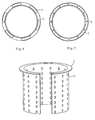
- the loudspeaker voice coil with a coil fixing mechanism comprises a cylindrical voice coil bobbin 1, a coil 4 and a conical diaphragm and an damper (not shown) fixed on the voice coil bobbin, a sleeve 3 wrapping around and adhering tightly to the bobbin 1 against its outer peripheral wall, the top and bottom ends of the sleeve are bent outward to form the collars 2, 5 ( to bend the portion in dash line to form the collars as shown in Fig.3 ), a groove 7 is formed of the collars 2, 5 together with the body of the sleeve constituting a fixing mechanism for the coil 4 so that the coil 4 is easily wound to adhere in the groove and its two ends are stopped by the collars 2, 5.
- the coil will not be slackened and dispersed apart or come off from the bobbin even if it is in the conditions that the voice coil bobbin under high power suffers heavier vibration and the cement used to stick the coil is heated to be softened.
- Fig.2 and Fig.4 it is possible that only one end of the sleeve 3 is bent outward to form a collar 2, while the other collar 6 for forming the groove 7 of the coil fixing mechanism is formed by bending outward the end of the voice coil bobbin, which end is adjacent to the coil.
- the coil 4 is wound in the groove 7 formed of the collar 2, 6 and the body of the sleeve 3, it can as well perform the same function of preventing the coil from being slackened and dispersed apart or coming off from the bobbin.
- the two ends of the sleeve before bending are cut to form some spaced notches on them first, then they are bent outward to form the collar surface with the notches 8 as shown in Fig.5.
- the sleeve 3 of the voice coil may as well consist of several disconnected lining bars 9 distributed evenly or unevenly over the outer periphery of the voice coil bobbin.
- the ends of the lining bars are bent outward to form collars to attach to the end of the coil for stopping it, which can as well make the coil adhere firmly to the voice coil bobbin and prevent the coil from being slackened and dispersed apart or coming off from the bobbin.
- the sleeve 3 is stamped with several holes on the surface, as shown in Fig. 7. It will increase not only the friction between the sleeve and the voice coil bobbin, but also their sticking firmness because of some cement remaining in the small holes. In addition, the holes also make the air discharging easily, no bubble existing between the sleeve 3 and the voice coil bobbin 1 and no separation will occur when they are adhered to each other. Similarly, to get the same effect, the part of the peripheral wall of the voice coil bobbin that attach to the sleeve 3 also can be stamped with holes, while the sleeve 3 can be either provided with smooth surface or stamped with holes.
- the material of the sleeve may be either non-magnet-conductive light alloy, or plastics or paper. If the light alloy is selected, a longitudinal groove shall be opened up for preventing eddy current from being generated in it and for serving as a compensation slot for thermal expansion and contraction. If plastics or paper is selected, more notches should be cut on the ends of the sleeve so as to facilitate the bending.
- the collars in the structure described above can also be acquired by externally connecting separate collars to the ends of the sleeve or the end of the voice coil bobbin in the way of sticking or scarf jointing.
- the present invention is not limited only to the embodiments described above. Any change or modification made for the invention in the scope of appended Claims shall be considered to be within the realm of the present invention.
Landscapes
- Physics & Mathematics (AREA)
- Engineering & Computer Science (AREA)
- Acoustics & Sound (AREA)
- Signal Processing (AREA)
- Audible-Bandwidth Dynamoelectric Transducers Other Than Pickups (AREA)
Applications Claiming Priority (2)
| Application Number | Priority Date | Filing Date | Title |
|---|---|---|---|
| CN02215494U CN2523162Y (zh) | 2002-01-28 | 2002-01-28 | 能防止散圈的音圈 |
| CN02215494 | 2002-01-28 |
Publications (2)
| Publication Number | Publication Date |
|---|---|
| EP1351548A2 true EP1351548A2 (de) | 2003-10-08 |
| EP1351548A3 EP1351548A3 (de) | 2004-11-03 |
Family
ID=4764264
Family Applications (1)
| Application Number | Title | Priority Date | Filing Date |
|---|---|---|---|
| EP02022733A Withdrawn EP1351548A3 (de) | 2002-01-28 | 2002-10-11 | Lautsprecherschwingspule mit Schwingspulenbefestigungsmechanismus |
Country Status (2)
| Country | Link |
|---|---|
| EP (1) | EP1351548A3 (de) |
| CN (1) | CN2523162Y (de) |
Cited By (3)
| Publication number | Priority date | Publication date | Assignee | Title |
|---|---|---|---|---|
| EP1601230A3 (de) * | 2004-05-24 | 2009-08-26 | Blast Loudspeakers Ltd. | Lautsprechersystem |
| CN106162462A (zh) * | 2016-08-18 | 2016-11-23 | 歌尔股份有限公司 | 一种音圈骨架及扬声器中的振动系统 |
| CN107404691A (zh) * | 2017-08-04 | 2017-11-28 | 奥音科技(镇江)有限公司 | 一种新型音圈 |
Family Cites Families (5)
| Publication number | Priority date | Publication date | Assignee | Title |
|---|---|---|---|---|
| NL30952C (de) * | 1930-04-03 | |||
| JPS5389728A (en) * | 1977-01-19 | 1978-08-07 | Sansui Electric Co | Loudspeaker unit |
| JP3311471B2 (ja) * | 1994-02-25 | 2002-08-05 | スター精密株式会社 | 電磁音響変換器及びその巻線の巻回方法 |
| DE4419250A1 (de) * | 1994-06-01 | 1995-12-07 | Nokia Deutschland Gmbh | Schwingspulenträger für Lautsprecher |
| US5734734A (en) * | 1995-12-29 | 1998-03-31 | Proni; Lucio | Audio voice coil adaptor ring |
-
2002
- 2002-01-28 CN CN02215494U patent/CN2523162Y/zh not_active Expired - Fee Related
- 2002-10-11 EP EP02022733A patent/EP1351548A3/de not_active Withdrawn
Cited By (5)
| Publication number | Priority date | Publication date | Assignee | Title |
|---|---|---|---|---|
| EP1601230A3 (de) * | 2004-05-24 | 2009-08-26 | Blast Loudspeakers Ltd. | Lautsprechersystem |
| CN106162462A (zh) * | 2016-08-18 | 2016-11-23 | 歌尔股份有限公司 | 一种音圈骨架及扬声器中的振动系统 |
| CN106162462B (zh) * | 2016-08-18 | 2019-09-17 | 歌尔股份有限公司 | 一种音圈骨架及扬声器中的振动系统 |
| CN107404691A (zh) * | 2017-08-04 | 2017-11-28 | 奥音科技(镇江)有限公司 | 一种新型音圈 |
| CN107404691B (zh) * | 2017-08-04 | 2023-08-18 | 奥音科技(镇江)有限公司 | 一种新型音圈 |
Also Published As
| Publication number | Publication date |
|---|---|
| CN2523162Y (zh) | 2002-11-27 |
| EP1351548A3 (de) | 2004-11-03 |
Similar Documents
| Publication | Publication Date | Title |
|---|---|---|
| EP1492382A2 (de) | Lautsprecher mit zwei symmetrischen magnetischen Kreisen,zwei Schwingspulen und zwei Dämpfern | |
| CN107079221A (zh) | 电声变换器 | |
| JP2006121602A (ja) | スピーカー装置及びその製造方法 | |
| US4322584A (en) | Voice coil bobbin for planar diaphragm | |
| EP1351548A2 (de) | Lautsprecherschwingspule mit Schwingspulenbefestigungsmechanismus | |
| WO2017166375A1 (zh) | 音圈及设有该音圈的微型扬声器 | |
| US20060159300A1 (en) | Spider with leadwires sandwiched | |
| CN112533112A (zh) | 一种双磁路结构及发声器件 | |
| JP2007096453A (ja) | スピーカ | |
| JPH09275598A (ja) | スピーカ用センターリングスパイダ及びこれを用いたスピーカ | |
| US5581624A (en) | Loudspeaker suitable for high-temperature use having a non-adhesive connection between the voice coil support and the loudspeaker diaphragm | |
| JPH06292296A (ja) | スピーカー | |
| US2320402A (en) | Loud-speaker | |
| JP2005269334A (ja) | スピーカ装置 | |
| JP2944992B1 (ja) | 紙製リール | |
| JP7414254B2 (ja) | 電気音響変換器と電気音響変換器の製造方法 | |
| JP3879755B2 (ja) | スピーカーの製造方法 | |
| JPH08251693A (ja) | スピーカー用ボイスコイル一体型振動板 | |
| JP2004120665A (ja) | ボイスコイルボビン | |
| CN222395815U (zh) | 一种扬声器 | |
| JPH07131892A (ja) | コイルの巻回方法 | |
| KR100676401B1 (ko) | 소형 전자음향변환기의 진동판 | |
| JP2002125294A (ja) | 動電形スピーカ | |
| CN207369283U (zh) | 借由黏着剂固定导线的喇叭振动片 | |
| JP2003160278A (ja) | 紙ツバ切込みリール |
Legal Events
| Date | Code | Title | Description |
|---|---|---|---|
| PUAI | Public reference made under article 153(3) epc to a published international application that has entered the european phase |
Free format text: ORIGINAL CODE: 0009012 |
|
| AK | Designated contracting states |
Kind code of ref document: A2 Designated state(s): AT BE BG CH CY CZ DE DK EE ES FI FR GB GR IE IT LI LU MC NL PT SE SK TR |
|
| AX | Request for extension of the european patent |
Extension state: AL LT LV MK RO SI |
|
| PUAL | Search report despatched |
Free format text: ORIGINAL CODE: 0009013 |
|
| AK | Designated contracting states |
Kind code of ref document: A3 Designated state(s): AT BE BG CH CY CZ DE DK EE ES FI FR GB GR IE IT LI LU MC NL PT SE SK TR |
|
| AX | Request for extension of the european patent |
Extension state: AL LT LV MK RO SI |
|
| 17P | Request for examination filed |
Effective date: 20050503 |
|
| AKX | Designation fees paid |
Designated state(s): AT BE BG CH CY CZ DE DK EE ES FI FR GB GR IE IT LI LU MC NL PT SE SK TR |
|
| STAA | Information on the status of an ep patent application or granted ep patent |
Free format text: STATUS: THE APPLICATION IS DEEMED TO BE WITHDRAWN |
|
| 18D | Application deemed to be withdrawn |
Effective date: 20051126 |