EP1353432A2 - Magnetanordnung für drehende elektrische Maschine - Google Patents
Magnetanordnung für drehende elektrische Maschine Download PDFInfo
- Publication number
- EP1353432A2 EP1353432A2 EP03008268A EP03008268A EP1353432A2 EP 1353432 A2 EP1353432 A2 EP 1353432A2 EP 03008268 A EP03008268 A EP 03008268A EP 03008268 A EP03008268 A EP 03008268A EP 1353432 A2 EP1353432 A2 EP 1353432A2
- Authority
- EP
- European Patent Office
- Prior art keywords
- rotating electrical
- electrical machine
- magnet arrangement
- set forth
- magnet
- Prior art date
- Legal status (The legal status is an assumption and is not a legal conclusion. Google has not performed a legal analysis and makes no representation as to the accuracy of the status listed.)
- Withdrawn
Links
Images




Classifications
-
- H—ELECTRICITY
- H02—GENERATION; CONVERSION OR DISTRIBUTION OF ELECTRIC POWER
- H02K—DYNAMO-ELECTRIC MACHINES
- H02K1/00—Details of the magnetic circuit
- H02K1/06—Details of the magnetic circuit characterised by the shape, form or construction
- H02K1/22—Rotating parts of the magnetic circuit
- H02K1/27—Rotor cores with permanent magnets
- H02K1/2786—Outer rotors
- H02K1/2787—Outer rotors the magnetisation axis of the magnets being perpendicular to the rotor axis
- H02K1/2789—Outer rotors the magnetisation axis of the magnets being perpendicular to the rotor axis the rotor consisting of two or more circumferentially positioned magnets
- H02K1/2791—Surface mounted magnets; Inset magnets
Definitions
- This invention relates to a magnets mounting structure for a rotary electric machine and particularly to a magnet holding structure wherein the individual permanent magnets are physically retained in position.
- a plurality of permanent magnets are positioned in confronting relation to electrical coils. Generally this is done by positioning a slotted ring in engagement with a cylindrical shell. The permanent magnets are loosely positioned in the slots of the ring. An adhesive is then inserted between the walls of the slots and the magnets to retain them in position.
- the magnets when ferrite based magnets were used, the magnets generally had a thickness of 5 mm or more, and the holder ring, too, had a thickness corresponding to that of the magnets.
- ferrite based permanent magnets are being replaced by high energy neodymium (Nd) based magnets.
- Nd neodymium
- the magnets can be reduced significantly in thickness. Thickness are generally 3mm or less, however the magnetic force is increased from that of ferrite based magnets so that increased output is effected.
- the invention is adapted to be embodied in a magnet arrangement for a rotating electrical machine.
- the machine is comprised of a cylindrical shell and a magnet carrier having a cylindrical portion complimentary to and engaged with a surface of the cylindrical shell.
- the magnet carrier is formed with a plurality of circumferentially spaced, axially extending projections defining open ended gaps therebetween.
- a plurality of permanent magnets are provided with each magnet being received and physically retained in a respective one of the gaps
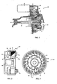
- FIG. 1 is a cross sectional view taken through a portion of an internal combustion engine having an electrical generator constructed in accordance with an embodiment of the invention.
- FIG. 2 is an enlarged view, in part similar to FIG. 1, but shows more detail of the generator and its attachment to the driving shaft of the engine.
- FIG. 3 is an end elevational view looking in the direction of the arrow 3 in FIG. 2.
- FIG. 4 is an exploded perspective view of the magnet assembly constructed in accordance with a first embodiment.
- FIG. 5 is an end view of one of the permanent magnets.
- FIG. 6 is a side elevational view of one of the permanent magnets.
- FIG. 7 is an end view of a magnet holder constructed in accordance with another embodiment.
- FIG. 8 is an side elevational view of the magnet holder in accordance with this other embodiment
- FIG. 9 is end view of the magnet carrier or rotor of this embodiment a side elevational view of the magnet holder constructed in accordance with this embodiment and is taken in the direction of the arrows 9-9 of FIG. 10.
- FIG. 10 is a cross sectional of the magnet carrier or rotor of this embodiment taken along the line 10-10 of FIG. 9.
- FIG. 11 is end view, in part similar to FIG. 7 of a complete magnet holder constructed in accordance with another embodiment taken in the direction of the arrows 11-11 of FIG. 12. 2.
- FIG. 12 is a cross sectional of the magnet holder of this embodiment looking in the direction of the line 12-12 of FIG. 11.
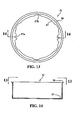
- FIG. 13 is end view of an inner casing taken in the direction of the arrows 13-13 of FIG. 14.
- FIG. 14 is a cross sectional of the inner casing looking in the direction of the line 14-14 of FIG. 13.
- FIG. 1 a portion of a motor vehicle engine is illustrated in part and partially in cross section, indicated generally at 21.
- Such an application is utilized as this is a typical environment in which the invention may be utilized.
- those skilled in the art will readily recognize other applications for the invention.
- the engine 21 includes an electric starter motor 22 that is fixed to the engine body 23.
- An output gear 24 of the starter motor 22 is drives a reduction gear 25 via an intermediate gear 26.
- the reduction gear 25 drives a starter gear 27.
- the started gear 27 is coupled via a one way clutch 28 to a drive ring 29.
- the drive ring 29, in turn, is coupled to the rotor 31 of an electrical generator, indicated generally at 32, and which embodies the invention.
- the rotor 31 cooperates with a stator 33 that is fixed to the engine frame 23.
- the stator has poles around which coils are wound, as is well known in the art. These coils cooperate with permanent magnets 34 fixed in a manner according to the invention as will be described later initially by reference to FIGS. 2 and 3.
- the magnets 34 are held in a magnet holder indicated in this figure as 35.
- the rotor 31 is connected to a hub 36 fixed secured to the end of a speed increasing shaft 37 with a bolt 38 and a key (not shown).
- the speed increasing shaft 37 is rotatably mounted on the engine body 23 through a bolt 39 and a bearing (not shown).
- the speed increasing shaft 37 is provided with a speed increasing gear 41.
- the speed increasing gear 41 is connected to a crankshaft (not shown).
- the turning action of the starter motor 22 is reduced in speed and transmitted to the starter gear 27, which in turn rotates the hub 36 via the one-way clutch 28. Accordingly, the rotational action of the crankshaft starts via the speed increasing shaft 37 to cause the engine to start. When the crankshaft rotates at higher speed than the starter motor 22 the clutch 28 will overrun.
- the generator 32 is constructed so that that the rotor assembly 31 is mounted around the stator assembly 33.
- This stator assembly 33 includes a plurality of (in this example, eighteen) coils 42 wound around cores 43.
- the rotor assembly 31, as described above, is arranged such that the magnets 34 are held by the holder ring 35 mounted to the inner side of a rotor outer cylinder body portion 44, the magnets 54 are internally pressed against the rotor outer cylinder body portion 44 in a manner to be described later, by reference to the remaining figures.
- the rotor outer cylinder 44 is secured to the hub 36 with bolts or rivets 45.
- the connecting hub 36 has a conical, tapered-shaped mounting hole 46 for mounting on the shaft 37.
- the reference numeral 48 designates a 3-phase cable for the coil windings 42.
- the rotor 31 is comprised of the rotor outer cylinder body 44 with the magnet holder ring 35 fitted to the inner side thereof.
- the magnet pressing member afore referred to comprises an inner casing 51 further fitted to the inner side of the holder ring 35.
- a plurality of magnets 54 are held by the holder ring 35.
- the rotor outer cylinder 44 is entirely opened at one end and is closed at the other end by an integral end plate 52 at the other end thereof.
- an outer edge 53 Around the perimeter of the upper end of the side wall is formed an outer edge 53 with a step 54 on the inner side thereof.
- the holder ring 35 is made of resin and has a plurality of axially extending projections 55 projecting toward the open end (upper end) side of the side wall at regular intervals.
- the slots thus formed between the respective projections 55 are inserted and held eighteen, for example, magnets 34 in a press-fitted state. Accordingly, the slots formed between the respective projections 55 is equal to or slightly smaller than the width of the magnet 34 so that the projection 55 and the magnet 34 are in press contact with each other.
- Press-contacting ribs as shown in FIGS. 7 and 8 to be described shortly, may be provided on the sides of the respective projections 55.
- the projections 55 have a axial length at least half the length of the magnets 34 or longer. Therefore, the magnets 34 can securely be held by the projections 55.
- the inner casing 51 has an outer radially extending flange 56 at its upper edge and a radially extending inner flange 57 at its lower edge.
- FIGS. 5 and 6 are a top and a front view, respectively, of the magnets 34.
- the magnets 34 are high-energy, neodymium-based magnets and are radially disposed around the inner periphery side of the rotor outer cylinder 44. As shown in a FIG. 5 the magnets 34 have an arcuate shape in section around the inner periphery of the rotor outer cylinder 44 and a thickness of 3mm or less.
- the press fitting of the magnets 34 into the slots formed between the projections 55 can be facilitated by forming ribs on the edges of the projections 55.
- the holder ring 35 has the plurality of projections 55. These extend axially from the upper edge of a ring part 58 at regular intervals in a tooth-like manner.
- the space between the projections 55 has such a width that the magnet 34 will be in press-contact therewith
- the projections 55 have a length of half the magnet or longer.
- longitudinal ribs 59 project from the sides of the respective projections 55.
- the rotor outer cylinder has the cylindrical side wall 44 which is entirely opened at its upper end and has the end plate 52 at its lower end.
- the outer edge 55 Around the perimeter of the upper end of the side wall 44 is formed the outer edge 55, and on the inner side thereof is formed the step 54.
- mounting holes 61 for mounting the rotor outer cylinder 44 on the connecting wheel 36 shown in FIG.1.
- bolt-through connecting holes 62 are formed for connecting the rotor outer cylinder 44 to the one-way clutch 28.
- mounting holes 63 for mounting the inner flange 57 of the inner casing 51 to the rotor outer cylinder 44. When so mounted, the outer flange 56 of the inner casing 51 may be locked in position by inwardly bending the edge 55 toward the step 42.
- the magnet holder ring 35 is shown enlarged in FIGS 11 and 12 and the parts already described in detail above are indicated by the same reference numerals. Further description of these figures, therefore is not believed to be necessary.
- FIGS. 13 and 14 are enlarged views of the inner casing 51 which also has been described in detail. However these views also show that the inner flange 57 are formed mounting holes or notches 57a in alignment with the mounting holes 63 (FIGS. 9 and 10) in the end plate 52 of the rotor outer cylinder 44.
- the reference numeral 57b designates recesses corresponding to accommodate bolts 45 (FIG. 1) inserted into six connecting holes 62 in the end plate 52.
- magnet retainers for rotating electrical machines that provide excellent magnet retention even if very thin high strength magnets are employed and without requiring adhesives.
Landscapes
- Engineering & Computer Science (AREA)
- Power Engineering (AREA)
- Permanent Field Magnets Of Synchronous Machinery (AREA)
Applications Claiming Priority (4)
| Application Number | Priority Date | Filing Date | Title |
|---|---|---|---|
| JP2002107538A JP2003304660A (ja) | 2002-04-10 | 2002-04-10 | 回転電気機器のロータ構造 |
| JP2002107538 | 2002-04-10 | ||
| US249378 | 2003-04-03 | ||
| US10/249,378 US20030193254A1 (en) | 2002-04-10 | 2003-04-03 | Magnet arrangement for rotating electrical machine |
Publications (2)
| Publication Number | Publication Date |
|---|---|
| EP1353432A2 true EP1353432A2 (de) | 2003-10-15 |
| EP1353432A3 EP1353432A3 (de) | 2005-10-26 |
Family
ID=28786467
Family Applications (1)
| Application Number | Title | Priority Date | Filing Date |
|---|---|---|---|
| EP03008268A Withdrawn EP1353432A3 (de) | 2002-04-10 | 2003-04-09 | Magnetanordnung für drehende elektrische Maschine |
Country Status (5)
| Country | Link |
|---|---|
| US (1) | US20030193254A1 (de) |
| EP (1) | EP1353432A3 (de) |
| JP (1) | JP2003304660A (de) |
| CN (1) | CN1450710A (de) |
| TW (1) | TW200306049A (de) |
Cited By (3)
| Publication number | Priority date | Publication date | Assignee | Title |
|---|---|---|---|---|
| DE102007017215A1 (de) * | 2007-04-12 | 2008-10-16 | Schaeffler Kg | Rotatorischer Direktantrieb |
| CN101860157A (zh) * | 2010-06-22 | 2010-10-13 | 哈尔滨工业大学 | 外转子永磁同步电机 |
| EP1763122A3 (de) * | 2005-09-13 | 2015-10-21 | LG Electronics Inc. | Motor und diesen enthaltende Waschmaschine |
Families Citing this family (7)
| Publication number | Priority date | Publication date | Assignee | Title |
|---|---|---|---|---|
| US7859124B2 (en) * | 2006-08-16 | 2010-12-28 | Andreas Stihl Ag & Co. Kg | Internal combustion engine with alternator |
| KR100973737B1 (ko) * | 2008-09-30 | 2010-08-04 | 대동모벨시스템 주식회사 | 브러쉬레스 직류 전동기 |
| GB2511574B (en) * | 2013-03-08 | 2017-10-04 | Magnomatics Ltd | Permanent magnet assembly for mounting to a rotor |
| EP3657641B1 (de) | 2018-11-26 | 2023-09-06 | LG Electronics Inc. | Motor |
| JP7208946B2 (ja) | 2020-04-07 | 2023-01-19 | シナノケンシ株式会社 | 回転子、回転子の製造方法及びモータ |
| JP7208945B2 (ja) | 2020-04-07 | 2023-01-19 | シナノケンシ株式会社 | 回転子、回転子の製造方法及びモータ |
| CN112615496B (zh) * | 2020-12-18 | 2025-08-12 | 卧龙电气驱动集团股份有限公司 | 一种用于外转子电机磁钢的安装工装 |
Family Cites Families (18)
| Publication number | Priority date | Publication date | Assignee | Title |
|---|---|---|---|---|
| US3828212A (en) * | 1971-09-16 | 1974-08-06 | Briggs & Stratton Corp | Assembly of alternator magnet blocks with engine flywheel |
| JPS5923180B2 (ja) * | 1976-06-23 | 1984-05-31 | 株式会社日立製作所 | 磁石発電機の回転子 |
| JPS589500Y2 (ja) * | 1977-06-24 | 1983-02-21 | 株式会社デンソー | 磁石発電機の回転子 |
| JPS611247A (ja) * | 1984-06-11 | 1986-01-07 | Mitsuba Denki Seisakusho:Kk | 磁石発電機の回転子およびその製造方法 |
| DE3673875D1 (de) * | 1985-06-06 | 1990-10-11 | Nippon Denso Co | Magnetlaeufer. |
| GB8606494D0 (en) * | 1986-03-17 | 1986-04-23 | Johnson Electric Ind Mfg | Electric motor |
| US4795932A (en) * | 1987-07-31 | 1989-01-03 | United Technologies Electro Systems, Inc. | Double insulated motor including a magnet retainer |
| JPH07118873B2 (ja) * | 1989-06-30 | 1995-12-18 | 株式会社三ツ葉電機製作所 | 磁石発電機の回転子 |
| JPH0374152A (ja) * | 1989-08-11 | 1991-03-28 | Mitsuba Electric Mfg Co Ltd | 磁石発電機の回転子 |
| JP2947586B2 (ja) * | 1990-03-30 | 1999-09-13 | 日本電産株式会社 | スピンドルモータ |
| JPH07118874B2 (ja) * | 1990-08-01 | 1995-12-18 | 株式会社三ツ葉電機製作所 | 回転電機の界磁装置 |
| US5281881A (en) * | 1993-02-25 | 1994-01-25 | General Motors Corporation | Frame and magnet assembly for a dynamoelectric machine |
| JPH0823647A (ja) * | 1994-07-07 | 1996-01-23 | Hitachi Ltd | マグネットモータの界磁固定装置 |
| JP3488532B2 (ja) * | 1995-01-24 | 2004-01-19 | 株式会社ミツバ | 回転電機の固定子 |
| JP3612103B2 (ja) * | 1995-03-03 | 2005-01-19 | 株式会社ミツバ | マグネットホルダユニットおよびその生産方法 |
| JPH0956091A (ja) * | 1995-08-18 | 1997-02-25 | Mitsubishi Electric Corp | 永久磁石式回転電機 |
| JPH11113200A (ja) * | 1997-09-30 | 1999-04-23 | Mitsumi Electric Co Ltd | 小型モータ |
| US6060799A (en) * | 1999-03-31 | 2000-05-09 | Webster Plastics | Magnet carrier for motor housing |
-
2002
- 2002-04-10 JP JP2002107538A patent/JP2003304660A/ja active Pending
-
2003
- 2003-04-03 US US10/249,378 patent/US20030193254A1/en not_active Abandoned
- 2003-04-09 EP EP03008268A patent/EP1353432A3/de not_active Withdrawn
- 2003-04-10 CN CN03110406A patent/CN1450710A/zh active Pending
- 2003-04-10 TW TW092108236A patent/TW200306049A/zh unknown
Cited By (4)
| Publication number | Priority date | Publication date | Assignee | Title |
|---|---|---|---|---|
| EP1763122A3 (de) * | 2005-09-13 | 2015-10-21 | LG Electronics Inc. | Motor und diesen enthaltende Waschmaschine |
| DE102007017215A1 (de) * | 2007-04-12 | 2008-10-16 | Schaeffler Kg | Rotatorischer Direktantrieb |
| DE102007017215B4 (de) * | 2007-04-12 | 2017-01-12 | Schaeffler Technologies AG & Co. KG | Rotatorischer Direktantrieb |
| CN101860157A (zh) * | 2010-06-22 | 2010-10-13 | 哈尔滨工业大学 | 外转子永磁同步电机 |
Also Published As
| Publication number | Publication date |
|---|---|
| EP1353432A3 (de) | 2005-10-26 |
| JP2003304660A (ja) | 2003-10-24 |
| CN1450710A (zh) | 2003-10-22 |
| US20030193254A1 (en) | 2003-10-16 |
| TW200306049A (en) | 2003-11-01 |
Similar Documents
| Publication | Publication Date | Title |
|---|---|---|
| KR100222510B1 (ko) | 영구자석 다이나모-전기 기계 | |
| US7906883B2 (en) | Axial gap motor | |
| US6265802B1 (en) | Laminated rotor assembly and method for a dynamoelectric machine | |
| EP1895638A2 (de) | Rotationselektrogerät | |
| US7365466B2 (en) | Rotor for an electrical motor | |
| CN102934329A (zh) | 电动机的转子及其制造方法 | |
| EP1353432A2 (de) | Magnetanordnung für drehende elektrische Maschine | |
| JP5741960B2 (ja) | 回転子およびそれを用いた回転電機 | |
| US12562616B2 (en) | Motor with expandable casing | |
| US7619343B2 (en) | Rotor for an electrical motor | |
| JP3397119B2 (ja) | 回転電機用磁石回転子 | |
| EP1104077A3 (de) | Permanentmagnetischer rotierender Elektromotor | |
| JP2005057932A (ja) | モータ | |
| JP4436652B2 (ja) | 磁石式発電機 | |
| JP2004064925A (ja) | ブラシレスモータ | |
| KR101964423B1 (ko) | 로터 및 이를 포함하는 모터 | |
| JP2010178485A (ja) | モータ、その回転子、およびその製造方法 | |
| JP5225666B2 (ja) | 永久磁石型の回転電機 | |
| JP4705639B2 (ja) | 磁石回転子及び交流発電機 | |
| JP3281245B2 (ja) | 磁石発電機の回転子 | |
| US20240421680A1 (en) | Motor with expandable casing | |
| JPH1169675A (ja) | 回転電機の巻線界磁型ロータ | |
| JPH11103542A (ja) | 回転電機 | |
| JPH0724937Y2 (ja) | 偏平ロ−タ型ブラシレスモ−タ | |
| JP2002199660A (ja) | 回転子への磁気センサ用マグネットの固定構造 |
Legal Events
| Date | Code | Title | Description |
|---|---|---|---|
| PUAI | Public reference made under article 153(3) epc to a published international application that has entered the european phase |
Free format text: ORIGINAL CODE: 0009012 |
|
| AK | Designated contracting states |
Kind code of ref document: A2 Designated state(s): AT BE BG CH CY CZ DE DK EE ES FI FR GB GR HU IE IT LI LU MC NL PT SE SI SK TR |
|
| AX | Request for extension of the european patent |
Extension state: AL LT LV MK RO |
|
| PUAL | Search report despatched |
Free format text: ORIGINAL CODE: 0009013 |
|
| AK | Designated contracting states |
Kind code of ref document: A3 Designated state(s): AT BE BG CH CY CZ DE DK EE ES FI FR GB GR HU IE IT LI LU MC NL PT SE SI SK TR |
|
| AX | Request for extension of the european patent |
Extension state: AL LT LV MK RO |
|
| AKX | Designation fees paid |
Designated state(s): DE FR IT |
|
| STAA | Information on the status of an ep patent application or granted ep patent |
Free format text: STATUS: THE APPLICATION IS DEEMED TO BE WITHDRAWN |
|
| 18D | Application deemed to be withdrawn |
Effective date: 20060427 |