EP1355769B1 - Machine automatique a poser des pointes flexibles sur un cadre - Google Patents
Machine automatique a poser des pointes flexibles sur un cadre Download PDFInfo
- Publication number
- EP1355769B1 EP1355769B1 EP01995759A EP01995759A EP1355769B1 EP 1355769 B1 EP1355769 B1 EP 1355769B1 EP 01995759 A EP01995759 A EP 01995759A EP 01995759 A EP01995759 A EP 01995759A EP 1355769 B1 EP1355769 B1 EP 1355769B1
- Authority
- EP
- European Patent Office
- Prior art keywords
- gun
- rack
- frame
- gripper
- machine
- Prior art date
- Legal status (The legal status is an assumption and is not a legal conclusion. Google has not performed a legal analysis and makes no representation as to the accuracy of the status listed.)
- Expired - Lifetime
Links
- 238000009434 installation Methods 0.000 description 2
- 230000007246 mechanism Effects 0.000 description 1
- 238000000465 moulding Methods 0.000 description 1
- 238000007789 sealing Methods 0.000 description 1
- 230000000007 visual effect Effects 0.000 description 1
Images
Classifications
-
- B—PERFORMING OPERATIONS; TRANSPORTING
- B27—WORKING OR PRESERVING WOOD OR SIMILAR MATERIAL; NAILING OR STAPLING MACHINES IN GENERAL
- B27F—DOVETAILED WORK; TENONS; SLOTTING MACHINES FOR WOOD OR SIMILAR MATERIAL; NAILING OR STAPLING MACHINES
- B27F7/00—Nailing or stapling; Nailed or stapled work
- B27F7/006—Nailing or stapling machines provided with means for operating on discrete points
-
- Y—GENERAL TAGGING OF NEW TECHNOLOGICAL DEVELOPMENTS; GENERAL TAGGING OF CROSS-SECTIONAL TECHNOLOGIES SPANNING OVER SEVERAL SECTIONS OF THE IPC; TECHNICAL SUBJECTS COVERED BY FORMER USPC CROSS-REFERENCE ART COLLECTIONS [XRACs] AND DIGESTS
- Y10—TECHNICAL SUBJECTS COVERED BY FORMER USPC
- Y10T—TECHNICAL SUBJECTS COVERED BY FORMER US CLASSIFICATION
- Y10T29/00—Metal working
- Y10T29/53—Means to assemble or disassemble
- Y10T29/53039—Means to assemble or disassemble with control means energized in response to activator stimulated by condition sensor
-
- Y—GENERAL TAGGING OF NEW TECHNOLOGICAL DEVELOPMENTS; GENERAL TAGGING OF CROSS-SECTIONAL TECHNOLOGIES SPANNING OVER SEVERAL SECTIONS OF THE IPC; TECHNICAL SUBJECTS COVERED BY FORMER USPC CROSS-REFERENCE ART COLLECTIONS [XRACs] AND DIGESTS
- Y10—TECHNICAL SUBJECTS COVERED BY FORMER USPC
- Y10T—TECHNICAL SUBJECTS COVERED BY FORMER US CLASSIFICATION
- Y10T29/00—Metal working
- Y10T29/53—Means to assemble or disassemble
- Y10T29/53039—Means to assemble or disassemble with control means energized in response to activator stimulated by condition sensor
- Y10T29/53061—Responsive to work or work-related machine element
-
- Y—GENERAL TAGGING OF NEW TECHNOLOGICAL DEVELOPMENTS; GENERAL TAGGING OF CROSS-SECTIONAL TECHNOLOGIES SPANNING OVER SEVERAL SECTIONS OF THE IPC; TECHNICAL SUBJECTS COVERED BY FORMER USPC CROSS-REFERENCE ART COLLECTIONS [XRACs] AND DIGESTS
- Y10—TECHNICAL SUBJECTS COVERED BY FORMER USPC
- Y10T—TECHNICAL SUBJECTS COVERED BY FORMER US CLASSIFICATION
- Y10T29/00—Metal working
- Y10T29/53—Means to assemble or disassemble
- Y10T29/53039—Means to assemble or disassemble with control means energized in response to activator stimulated by condition sensor
- Y10T29/53061—Responsive to work or work-related machine element
- Y10T29/53065—Responsive to work or work-related machine element with means to fasten by deformation
- Y10T29/5307—Self-piercing work part
-
- Y—GENERAL TAGGING OF NEW TECHNOLOGICAL DEVELOPMENTS; GENERAL TAGGING OF CROSS-SECTIONAL TECHNOLOGIES SPANNING OVER SEVERAL SECTIONS OF THE IPC; TECHNICAL SUBJECTS COVERED BY FORMER USPC CROSS-REFERENCE ART COLLECTIONS [XRACs] AND DIGESTS
- Y10—TECHNICAL SUBJECTS COVERED BY FORMER USPC
- Y10T—TECHNICAL SUBJECTS COVERED BY FORMER US CLASSIFICATION
- Y10T29/00—Metal working
- Y10T29/53—Means to assemble or disassemble
- Y10T29/53478—Means to assemble or disassemble with magazine supply
-
- Y—GENERAL TAGGING OF NEW TECHNOLOGICAL DEVELOPMENTS; GENERAL TAGGING OF CROSS-SECTIONAL TECHNOLOGIES SPANNING OVER SEVERAL SECTIONS OF THE IPC; TECHNICAL SUBJECTS COVERED BY FORMER USPC CROSS-REFERENCE ART COLLECTIONS [XRACs] AND DIGESTS
- Y10—TECHNICAL SUBJECTS COVERED BY FORMER USPC
- Y10T—TECHNICAL SUBJECTS COVERED BY FORMER US CLASSIFICATION
- Y10T29/00—Metal working
- Y10T29/53—Means to assemble or disassemble
- Y10T29/53478—Means to assemble or disassemble with magazine supply
- Y10T29/53522—Means to fasten by deforming
-
- Y—GENERAL TAGGING OF NEW TECHNOLOGICAL DEVELOPMENTS; GENERAL TAGGING OF CROSS-SECTIONAL TECHNOLOGIES SPANNING OVER SEVERAL SECTIONS OF THE IPC; TECHNICAL SUBJECTS COVERED BY FORMER USPC CROSS-REFERENCE ART COLLECTIONS [XRACs] AND DIGESTS
- Y10—TECHNICAL SUBJECTS COVERED BY FORMER USPC
- Y10T—TECHNICAL SUBJECTS COVERED BY FORMER US CLASSIFICATION
- Y10T29/00—Metal working
- Y10T29/53—Means to assemble or disassemble
- Y10T29/53709—Overedge assembling means
- Y10T29/5377—Riveter
Definitions
- the invention lies in the technical field of automated closing of the frames and door more precisely on an automatic machine for laying flexible tips.
- a machine to install nails to using a driving system the nails coming from a distribution store, a detector being able to signal the absence of nails in the store.
- a carriage can move longitudinally on rails. He wears one or more pistols, stapling. Each pistol is equipped with a flexible tip charger that should obviously be replace where to replenish, in case of jamming or when the spikes are exhausted. So this involves manipulation manual, with a temporary stop of the machine. It is also possible to use a recharging device automatic chargers, but this leads to heavy and expensive mechanisms. In addition these do not do not solve problems related to incidents of gun operation.
- the invention proposes a solution which consists in having in the vicinity of the station of work, a rack for the storage of pre-filled pistols flexible tips, which the machine will pick up as and as the contents of the pistols are stripped instead use the same gun (s) and refill them with tips.
- the main object of the invention is therefore a machine automatic to place flexible tips on a frame comprising a mobile carriage carrying a laying gun, which is movable above a trained workstation of a table carrying an endless band, said pistol containing a store full of drop-in points and the machine comprising a tip detector, characterized in that the machine is equipped with a rack for the storage of several pre-filled guns with spikes, rack which is accessible to a gripper of a pistol, gripper carried by said carriage, and in that the detector is mounted on the pistol to be able to notice the absence of a point in the frame at the place of installation, and order the operation of the clamp in the direction of the rack.
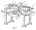
- the workstation is made up of a table 1, carrying an endless moving belt 2 and transversely to each end, a rail 3.
- a traveling crane 4 which itself supports a mobile carriage 5.
- the carriage movable longitudinally on the crane and transversely by the rails 3, is therefore able to cover the entire surface of the workstation.
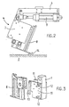
- Under the carriage 5 is attached to a pivoting lever 6 on which a clamp 7 which itself carries gun 8 intended for the installation of points on the frame, as also shown in Figure 2.
- a positioning cylinder 9 makes it possible to give the clamp, and consequently with the pistol, the inclination sought by relative to band 2 on which is immobilized temporarily frame 14 to be closed.
- a rack 10 On the side of the table 1 is arranged a rack 10, supporting, stored next to each other, a certain number of pistols 8 preloaded with flexible tips.
- the rack is accessible to the gripper 7 carried by the carriage 5, and it is advantageously arranged in front from table 1 and at conveyor belt 2.
- Figure 3 illustrates more precisely how ensured the attachment of the gun 8 to the clamp 7.
- the latter has two lateral sides 11 forming a vice, between which houses the pistol 8. These sides can open away from each other, side pins 12 providing guidance during this spacing.
- a lever 13 is articulated, actuator of the pistol trigger. Automatic air supply to the pistol is provided with a seal placed on the side of the sealing pliers.
- a first assumption is that the gun has not supplied as it is empty, this being confirmed by counting the peaks posed in relation to the capacity gun.
- the carriage 5 and its pivoting lever 6 are then move, to deposit the empty pistol on the rack 10 and take another full one, then for return to the top of frame 14 at the location of the last tip, to continue the laying cycle.
- a second hypothesis is that there is an anomaly of gun operation, detected by counting raised tips, which do not correspond to the total of tips stored at the start in the pistol. This last can go back to try a pose again, but in the event of further failure the pistol is renewed at rack 10 and replaced by another, as in the case previous.
- the machine thus makes it possible to obtain an hourly rate high of poses of points.
Landscapes
- Engineering & Computer Science (AREA)
- Mechanical Engineering (AREA)
- Life Sciences & Earth Sciences (AREA)
- Forests & Forestry (AREA)
- Automatic Assembly (AREA)
- Manipulator (AREA)
- Coating Apparatus (AREA)
- Automobile Manufacture Line, Endless Track Vehicle, Trailer (AREA)
- Control And Safety Of Cranes (AREA)
- Sewing Machines And Sewing (AREA)
- Biological Depolymerization Polymers (AREA)
- Soil Working Implements (AREA)
- Guiding Agricultural Machines (AREA)
- Portable Nailing Machines And Staplers (AREA)
Description
Claims (4)
- Machine automatique à poser des pointes flexibles sur un cadre comportant un chariot mobile (5) porteur d'un pistolet de pose (8) qui est déplaçable au dessus d'un poste de travail formé d'une table (1) portant une bande sans fin (2) ledit pistolet renfermant un magasin rempli de pointes à poser, et la machine comportant un détecteur de pointes (15), caractérisée en ce que la machine est équipée d'un râtelier (10) pour le stockage de plusieurs pistolets (8) préremplis de pointes, râtelier qui est accessible à une pince de préhension (7) d'un pistolet, pince portée par ledit chariot (5), et en ce que le détecteur (15) est monté sur le pistolet pour être en mesure de constater l'absence d'une pointe dans le cadre à l'endroit de la pose, et commande la manoeuvre de la pince en direction du râtelier.
- Machine automatique selon la revendication 1 caractérisée en ce que la pince (7) dispose de deux flancs latéraux (11) formant étau, entre lesquels se loge le pistolet (8).
- Machine automatique selon la revendication 2 caractérisée en ce que des pions (12) assurent le guidage des flancs latéraux (11) lors de leur écartement.
- Machine automatique selon la revendication 1 caractérisée en ce que une alimentation automatique d'air au pistolet (8) est prévu au niveau de la pince (7), avec un joint d'étanchéité.
Applications Claiming Priority (3)
| Application Number | Priority Date | Filing Date | Title |
|---|---|---|---|
| FR0100298A FR2819210B1 (fr) | 2001-01-11 | 2001-01-11 | Machine automatique a poser des pointes flexibles sur un cadre |
| FR0100298 | 2001-01-11 | ||
| PCT/FR2001/004156 WO2002055273A1 (fr) | 2001-01-11 | 2001-12-21 | Machine automatique a poser des pointes flexibles sur un cadre |
Publications (2)
| Publication Number | Publication Date |
|---|---|
| EP1355769A1 EP1355769A1 (fr) | 2003-10-29 |
| EP1355769B1 true EP1355769B1 (fr) | 2004-08-04 |
Family
ID=8858679
Family Applications (1)
| Application Number | Title | Priority Date | Filing Date |
|---|---|---|---|
| EP01995759A Expired - Lifetime EP1355769B1 (fr) | 2001-01-11 | 2001-12-21 | Machine automatique a poser des pointes flexibles sur un cadre |
Country Status (7)
| Country | Link |
|---|---|
| US (1) | US7010851B2 (fr) |
| EP (1) | EP1355769B1 (fr) |
| AT (1) | ATE272470T1 (fr) |
| DE (1) | DE60104725D1 (fr) |
| ES (1) | ES2225643T3 (fr) |
| FR (1) | FR2819210B1 (fr) |
| WO (1) | WO2002055273A1 (fr) |
Cited By (1)
| Publication number | Priority date | Publication date | Assignee | Title |
|---|---|---|---|---|
| CN111536412A (zh) * | 2020-04-28 | 2020-08-14 | 广东工业大学 | 一种用于汽车的lng自动专用加液机 |
Families Citing this family (11)
| Publication number | Priority date | Publication date | Assignee | Title |
|---|---|---|---|---|
| US7000658B1 (en) * | 2004-01-29 | 2006-02-21 | Harry Soukiassian | Precision adjustable woodworking platform |
| CA2537683A1 (fr) * | 2006-02-24 | 2007-08-24 | Luc Williams | Rampes en aluminium |
| US7954681B2 (en) * | 2007-10-02 | 2011-06-07 | Illinois Tool Works Inc. | Single tool nailing bridge system |
| CN103158125A (zh) * | 2011-12-09 | 2013-06-19 | 苏州工业园区高登威科技有限公司 | 机台 |
| CN103158124A (zh) * | 2011-12-09 | 2013-06-19 | 苏州工业园区高登威科技有限公司 | 机台 |
| CN103158123A (zh) * | 2011-12-09 | 2013-06-19 | 苏州工业园区高登威科技有限公司 | 机台 |
| US9757830B2 (en) * | 2014-12-04 | 2017-09-12 | Ronald P. Allen | Fencing assembly apparatus |
| EP3348368B1 (fr) * | 2017-01-13 | 2021-02-03 | Illinois Tool Works, Inc. | Module d'entraînement pourvu de chargeur amélioré |
| CN108928642B (zh) * | 2018-08-17 | 2020-07-10 | 珠海格力智能装备有限公司 | 支撑机构 |
| CN109732714B (zh) * | 2019-01-07 | 2021-08-03 | 深圳市诺亚创盟家具有限公司 | 一种环保节能型沙发精益生产线升降调节系统 |
| CN110282416A (zh) * | 2019-05-07 | 2019-09-27 | 重庆市盈科物联网信息技术有限公司 | 一种智能机械检修台 |
Family Cites Families (23)
| Publication number | Priority date | Publication date | Assignee | Title |
|---|---|---|---|---|
| US2743445A (en) * | 1953-03-17 | 1956-05-01 | Swingline Inc | Flexible cartridge or refill for stapling machines |
| US3556316A (en) * | 1967-03-03 | 1971-01-19 | American Mach & Foundry | Quick-change supply system |
| US3590463A (en) * | 1969-03-03 | 1971-07-06 | R K Lebond Machine Tool Co The | Tool changing method |
| US4026453A (en) * | 1976-03-31 | 1977-05-31 | Western Coat Pad Company | Variable work station for pneumatic stapling apparatus |
| IT1135119B (it) * | 1980-01-23 | 1986-08-20 | Jagenberg Werke Ag | Procedimento e dispositivo per il cambiamento di cassette-caricatori di etichette in macchine etichettatrici |
| US4486928A (en) * | 1981-07-09 | 1984-12-11 | Magnavox Government And Industrial Electronics Company | Apparatus for tool storage and selection |
| US4510684A (en) * | 1981-12-08 | 1985-04-16 | Zymark Corporation | Robot tool system |
| US4520550A (en) * | 1983-05-27 | 1985-06-04 | Automated Robotic Systems, Inc. | Robot tool changer |
| US4660274A (en) * | 1985-11-29 | 1987-04-28 | Goumas Peter G | Robot tool changing apparatus |
| US4941577A (en) * | 1988-07-21 | 1990-07-17 | Space Industries Partnership, L.P. | Portable robotic tool rack |
| JP2916021B2 (ja) * | 1991-04-18 | 1999-07-05 | オムロン株式会社 | 自動ステイプラの針無し検知装置 |
| US5123158A (en) * | 1991-04-26 | 1992-06-23 | Dixon Automatic Tool, Inc. | Automatic assembly machine with coordinately movable fastener driving gun and locating template |
| JPH05212704A (ja) * | 1991-06-12 | 1993-08-24 | Matsuda Rojisuteikusu Service Kk | ロボットによるステープル打ちまたは釘打ち装置 |
| JPH06238608A (ja) * | 1993-02-16 | 1994-08-30 | Kinoshita Komuten:Kk | 住宅パネル生産用釘打ちロボット |
| US5427297A (en) * | 1993-11-09 | 1995-06-27 | Tymianski; Marek | Feeding system for multiple riveting machine |
| DE4405661C2 (de) * | 1994-02-22 | 1998-01-29 | Fraunhofer Ges Forschung | Verfahren und Vorrichtung zum mechanischen Fügen von nichtmetallischen Werkstücken |
| US5463807A (en) * | 1994-09-08 | 1995-11-07 | Scovill Fasteners Inc. | Attaching machine for attaching fasteners |
| US5524807A (en) * | 1994-12-02 | 1996-06-11 | Bullard; Robert | Fastener tool |
| US5667126A (en) * | 1995-03-03 | 1997-09-16 | Boucek; Robert V. | Tool for actuating a pair of fastener ejecting guns |
| IT1278986B1 (it) * | 1995-03-10 | 1997-12-02 | Crea Srl | Macchina e procedimento per il piantaggio di inserti in pezzi di lamiera |
| US5716310A (en) * | 1995-11-01 | 1998-02-10 | Excellon Automation Company | Tool change apparatus |
| FR2748225B1 (fr) * | 1996-05-03 | 1998-07-31 | Renault Automation | Dispositif d'emmagasinage des outils d'une machine-outil d'usinage |
| US5950902A (en) * | 1998-06-10 | 1999-09-14 | Moore, Sr.; George Carlton | Corner bead fastening tool |
-
2001
- 2001-01-11 FR FR0100298A patent/FR2819210B1/fr not_active Expired - Fee Related
- 2001-12-21 EP EP01995759A patent/EP1355769B1/fr not_active Expired - Lifetime
- 2001-12-21 US US10/250,910 patent/US7010851B2/en not_active Expired - Fee Related
- 2001-12-21 DE DE60104725T patent/DE60104725D1/de not_active Expired - Lifetime
- 2001-12-21 ES ES01995759T patent/ES2225643T3/es not_active Expired - Lifetime
- 2001-12-21 WO PCT/FR2001/004156 patent/WO2002055273A1/fr not_active Ceased
- 2001-12-21 AT AT01995759T patent/ATE272470T1/de not_active IP Right Cessation
Cited By (2)
| Publication number | Priority date | Publication date | Assignee | Title |
|---|---|---|---|---|
| CN111536412A (zh) * | 2020-04-28 | 2020-08-14 | 广东工业大学 | 一种用于汽车的lng自动专用加液机 |
| CN111536412B (zh) * | 2020-04-28 | 2022-05-20 | 广东工业大学 | 一种用于汽车的lng自动专用加液机 |
Also Published As
| Publication number | Publication date |
|---|---|
| DE60104725D1 (de) | 2004-09-09 |
| ATE272470T1 (de) | 2004-08-15 |
| US7010851B2 (en) | 2006-03-14 |
| WO2002055273A1 (fr) | 2002-07-18 |
| FR2819210B1 (fr) | 2003-03-28 |
| US20040144445A1 (en) | 2004-07-29 |
| FR2819210A1 (fr) | 2002-07-12 |
| EP1355769A1 (fr) | 2003-10-29 |
| ES2225643T3 (es) | 2005-03-16 |
Similar Documents
| Publication | Publication Date | Title |
|---|---|---|
| EP1355769B1 (fr) | Machine automatique a poser des pointes flexibles sur un cadre | |
| EP3237123B1 (fr) | Installation pour la séparation et l'individualisation d'objets postaux hétérogènes | |
| FR2628021A1 (fr) | Appareil de scellement actionne par l'energie de la poudre | |
| FR2576336A1 (fr) | Dispositif d'epandage simultane de gravillons et de liant pour la refection des chaussees | |
| CN204209395U (zh) | 一种墨盒自动装配机 | |
| EP3858144A1 (fr) | Dispositif d'ajout de fourrage de kimchi, mécanisme de pulvérisation pour dispositif d'ajout de fourrage de kimchi, et dispositif de levage de dumpling pour dispositif d'ajout de fourrage de kimchi | |
| EP1980503B1 (fr) | Installation de délivrance d'objets, notamment pour pharmacie | |
| EP2354052A1 (fr) | Dispositif de distribution | |
| US4343390A (en) | Caser unit for containers | |
| EP0021986B1 (fr) | Dispositif pour déposer automatiquement une substance pâteuse sur une surface et machine automatique s'y rapportant | |
| EP3552720A1 (fr) | Installation de tri de courrier avec un convoyeur de bacs a rive escamotable et son robot navette manipulateur de bacs | |
| US3690994A (en) | Hand-carried yarn splicing device | |
| CN207455230U (zh) | 一种led灯组装机 | |
| US5960678A (en) | Automatic stress plate feeder | |
| US20220234128A1 (en) | Welding rod dispenser | |
| EP2168704A1 (fr) | Machine à fil mobile pour le découpage de pierre | |
| EP0146415A1 (fr) | Machine à coudre polyvalente pour la piqûre de pièces plates ou de pièces en forme | |
| FR2761500A1 (fr) | Machine semi-automatique pour apposer un dispositif anti-vol sur un article, notamment en tissu | |
| EP3797650B1 (fr) | Mobilier de rangement avec élément de rangement et methode d'utilisation | |
| JP3149757B2 (ja) | 板材の取出し装置 | |
| JP2012205582A (ja) | コンバイン | |
| WO2008031948A1 (fr) | Station de travail avec robot comportant une tête de positionnement et une tête de fixation, et procédé de fixation au moyen d'une telle station. | |
| FR2981242A1 (fr) | Station d'identification de porcelets et procede mettant en oeuvre une telle station | |
| FR2502767A1 (fr) | Dispositif de chargement pour arme a canon mobile incorporee a un vehicule blinde | |
| JPS588714Y2 (ja) | 缶蓋自動供給装置 |
Legal Events
| Date | Code | Title | Description |
|---|---|---|---|
| PUAI | Public reference made under article 153(3) epc to a published international application that has entered the european phase |
Free format text: ORIGINAL CODE: 0009012 |
|
| 17P | Request for examination filed |
Effective date: 20030715 |
|
| AK | Designated contracting states |
Kind code of ref document: A1 Designated state(s): AT BE CH CY DE DK ES FI FR GB GR IE IT LI LU MC NL PT SE TR |
|
| AX | Request for extension of the european patent |
Extension state: AL LT LV MK RO SI |
|
| RIN1 | Information on inventor provided before grant (corrected) |
Inventor name: CASSESE, PHILIPPE Inventor name: CASSESE, PIERRE Inventor name: CASSESE, JEAN Inventor name: CASSESE, ALAIN |
|
| GRAP | Despatch of communication of intention to grant a patent |
Free format text: ORIGINAL CODE: EPIDOSNIGR1 |
|
| GRAS | Grant fee paid |
Free format text: ORIGINAL CODE: EPIDOSNIGR3 |
|
| GRAA | (expected) grant |
Free format text: ORIGINAL CODE: 0009210 |
|
| AK | Designated contracting states |
Kind code of ref document: B1 Designated state(s): AT BE CH CY DE DK ES FI FR GB GR IE IT LI LU MC NL PT SE TR |
|
| PG25 | Lapsed in a contracting state [announced via postgrant information from national office to epo] |
Ref country code: IE Free format text: LAPSE BECAUSE OF FAILURE TO SUBMIT A TRANSLATION OF THE DESCRIPTION OR TO PAY THE FEE WITHIN THE PRESCRIBED TIME-LIMIT Effective date: 20040804 Ref country code: CY Free format text: LAPSE BECAUSE OF FAILURE TO SUBMIT A TRANSLATION OF THE DESCRIPTION OR TO PAY THE FEE WITHIN THE PRESCRIBED TIME-LIMIT Effective date: 20040804 Ref country code: FI Free format text: LAPSE BECAUSE OF FAILURE TO SUBMIT A TRANSLATION OF THE DESCRIPTION OR TO PAY THE FEE WITHIN THE PRESCRIBED TIME-LIMIT Effective date: 20040804 Ref country code: AT Free format text: LAPSE BECAUSE OF FAILURE TO SUBMIT A TRANSLATION OF THE DESCRIPTION OR TO PAY THE FEE WITHIN THE PRESCRIBED TIME-LIMIT Effective date: 20040804 Ref country code: TR Free format text: LAPSE BECAUSE OF FAILURE TO SUBMIT A TRANSLATION OF THE DESCRIPTION OR TO PAY THE FEE WITHIN THE PRESCRIBED TIME-LIMIT Effective date: 20040804 |
|
| REG | Reference to a national code |
Ref country code: GB Ref legal event code: FG4D Free format text: NOT ENGLISH |
|
| REG | Reference to a national code |
Ref country code: CH Ref legal event code: EP |
|
| REG | Reference to a national code |
Ref country code: IE Ref legal event code: FG4D Free format text: FRENCH |
|
| REF | Corresponds to: |
Ref document number: 60104725 Country of ref document: DE Date of ref document: 20040909 Kind code of ref document: P |
|
| GBT | Gb: translation of ep patent filed (gb section 77(6)(a)/1977) | ||
| PG25 | Lapsed in a contracting state [announced via postgrant information from national office to epo] |
Ref country code: GR Free format text: LAPSE BECAUSE OF FAILURE TO SUBMIT A TRANSLATION OF THE DESCRIPTION OR TO PAY THE FEE WITHIN THE PRESCRIBED TIME-LIMIT Effective date: 20041104 Ref country code: SE Free format text: LAPSE BECAUSE OF FAILURE TO SUBMIT A TRANSLATION OF THE DESCRIPTION OR TO PAY THE FEE WITHIN THE PRESCRIBED TIME-LIMIT Effective date: 20041104 Ref country code: DK Free format text: LAPSE BECAUSE OF FAILURE TO SUBMIT A TRANSLATION OF THE DESCRIPTION OR TO PAY THE FEE WITHIN THE PRESCRIBED TIME-LIMIT Effective date: 20041104 |
|
| PG25 | Lapsed in a contracting state [announced via postgrant information from national office to epo] |
Ref country code: DE Free format text: LAPSE BECAUSE OF FAILURE TO SUBMIT A TRANSLATION OF THE DESCRIPTION OR TO PAY THE FEE WITHIN THE PRESCRIBED TIME-LIMIT Effective date: 20041105 |
|
| PG25 | Lapsed in a contracting state [announced via postgrant information from national office to epo] |
Ref country code: LU Free format text: LAPSE BECAUSE OF NON-PAYMENT OF DUE FEES Effective date: 20041221 |
|
| PG25 | Lapsed in a contracting state [announced via postgrant information from national office to epo] |
Ref country code: MC Free format text: LAPSE BECAUSE OF NON-PAYMENT OF DUE FEES Effective date: 20041231 |
|
| LTIE | Lt: invalidation of european patent or patent extension |
Effective date: 20040804 |
|
| REG | Reference to a national code |
Ref country code: ES Ref legal event code: FG2A Ref document number: 2225643 Country of ref document: ES Kind code of ref document: T3 |
|
| REG | Reference to a national code |
Ref country code: IE Ref legal event code: FD4D |
|
| PLBE | No opposition filed within time limit |
Free format text: ORIGINAL CODE: 0009261 |
|
| STAA | Information on the status of an ep patent application or granted ep patent |
Free format text: STATUS: NO OPPOSITION FILED WITHIN TIME LIMIT |
|
| 26N | No opposition filed |
Effective date: 20050506 |
|
| PG25 | Lapsed in a contracting state [announced via postgrant information from national office to epo] |
Ref country code: CH Free format text: LAPSE BECAUSE OF NON-PAYMENT OF DUE FEES Effective date: 20051231 Ref country code: LI Free format text: LAPSE BECAUSE OF NON-PAYMENT OF DUE FEES Effective date: 20051231 |
|
| PG25 | Lapsed in a contracting state [announced via postgrant information from national office to epo] |
Ref country code: NL Free format text: LAPSE BECAUSE OF NON-PAYMENT OF DUE FEES Effective date: 20060701 |
|
| REG | Reference to a national code |
Ref country code: CH Ref legal event code: PL |
|
| NLV4 | Nl: lapsed or anulled due to non-payment of the annual fee |
Effective date: 20060701 |
|
| PG25 | Lapsed in a contracting state [announced via postgrant information from national office to epo] |
Ref country code: PT Free format text: LAPSE BECAUSE OF NON-PAYMENT OF DUE FEES Effective date: 20050104 |
|
| PGFP | Annual fee paid to national office [announced via postgrant information from national office to epo] |
Ref country code: IT Payment date: 20101127 Year of fee payment: 10 |
|
| PGFP | Annual fee paid to national office [announced via postgrant information from national office to epo] |
Ref country code: ES Payment date: 20111229 Year of fee payment: 11 |
|
| PG25 | Lapsed in a contracting state [announced via postgrant information from national office to epo] |
Ref country code: IT Free format text: LAPSE BECAUSE OF NON-PAYMENT OF DUE FEES Effective date: 20121221 |
|
| REG | Reference to a national code |
Ref country code: ES Ref legal event code: FD2A Effective date: 20140306 |
|
| PG25 | Lapsed in a contracting state [announced via postgrant information from national office to epo] |
Ref country code: ES Free format text: LAPSE BECAUSE OF NON-PAYMENT OF DUE FEES Effective date: 20121222 |
|
| PGFP | Annual fee paid to national office [announced via postgrant information from national office to epo] |
Ref country code: GB Payment date: 20141223 Year of fee payment: 14 |
|
| PGFP | Annual fee paid to national office [announced via postgrant information from national office to epo] |
Ref country code: FR Payment date: 20141230 Year of fee payment: 14 |
|
| PGFP | Annual fee paid to national office [announced via postgrant information from national office to epo] |
Ref country code: BE Payment date: 20141231 Year of fee payment: 14 |
|
| PG25 | Lapsed in a contracting state [announced via postgrant information from national office to epo] |
Ref country code: BE Free format text: LAPSE BECAUSE OF NON-PAYMENT OF DUE FEES Effective date: 20151231 |
|
| GBPC | Gb: european patent ceased through non-payment of renewal fee |
Effective date: 20151221 |
|
| REG | Reference to a national code |
Ref country code: FR Ref legal event code: ST Effective date: 20160831 |
|
| PG25 | Lapsed in a contracting state [announced via postgrant information from national office to epo] |
Ref country code: GB Free format text: LAPSE BECAUSE OF NON-PAYMENT OF DUE FEES Effective date: 20151221 |
|
| PG25 | Lapsed in a contracting state [announced via postgrant information from national office to epo] |
Ref country code: FR Free format text: LAPSE BECAUSE OF NON-PAYMENT OF DUE FEES Effective date: 20151231 |