EP1359046A2 - Verfahren und System zur Antriebskraftverteilung für ein Kraftfahrzeug mit Allradantrieb - Google Patents
Verfahren und System zur Antriebskraftverteilung für ein Kraftfahrzeug mit Allradantrieb Download PDFInfo
- Publication number
- EP1359046A2 EP1359046A2 EP03009320A EP03009320A EP1359046A2 EP 1359046 A2 EP1359046 A2 EP 1359046A2 EP 03009320 A EP03009320 A EP 03009320A EP 03009320 A EP03009320 A EP 03009320A EP 1359046 A2 EP1359046 A2 EP 1359046A2
- Authority
- EP
- European Patent Office
- Prior art keywords
- drive
- force
- map
- throttle opening
- vehicle
- Prior art date
- Legal status (The legal status is an assumption and is not a legal conclusion. Google has not performed a legal analysis and makes no representation as to the accuracy of the status listed.)
- Granted
Links
Images


Classifications
-
- B—PERFORMING OPERATIONS; TRANSPORTING
- B60—VEHICLES IN GENERAL
- B60K—ARRANGEMENT OR MOUNTING OF PROPULSION UNITS OR OF TRANSMISSIONS IN VEHICLES; ARRANGEMENT OR MOUNTING OF PLURAL DIVERSE PRIME-MOVERS IN VEHICLES; AUXILIARY DRIVES FOR VEHICLES; INSTRUMENTATION OR DASHBOARDS FOR VEHICLES; ARRANGEMENTS IN CONNECTION WITH COOLING, AIR INTAKE, GAS EXHAUST OR FUEL SUPPLY OF PROPULSION UNITS IN VEHICLES
- B60K23/00—Arrangement or mounting of control devices for vehicle transmissions, or parts thereof, not otherwise provided for
- B60K23/08—Arrangement or mounting of control devices for vehicle transmissions, or parts thereof, not otherwise provided for for changing number of driven wheels, for switching from driving one axle to driving two or more axles
- B60K23/0808—Arrangement or mounting of control devices for vehicle transmissions, or parts thereof, not otherwise provided for for changing number of driven wheels, for switching from driving one axle to driving two or more axles for varying torque distribution between driven axles, e.g. by transfer clutch
-
- B—PERFORMING OPERATIONS; TRANSPORTING
- B60—VEHICLES IN GENERAL
- B60K—ARRANGEMENT OR MOUNTING OF PROPULSION UNITS OR OF TRANSMISSIONS IN VEHICLES; ARRANGEMENT OR MOUNTING OF PLURAL DIVERSE PRIME-MOVERS IN VEHICLES; AUXILIARY DRIVES FOR VEHICLES; INSTRUMENTATION OR DASHBOARDS FOR VEHICLES; ARRANGEMENTS IN CONNECTION WITH COOLING, AIR INTAKE, GAS EXHAUST OR FUEL SUPPLY OF PROPULSION UNITS IN VEHICLES
- B60K17/00—Arrangement or mounting of transmissions in vehicles
- B60K17/34—Arrangement or mounting of transmissions in vehicles for driving both front and rear wheels, e.g. four wheel drive vehicles
- B60K17/348—Arrangement or mounting of transmissions in vehicles for driving both front and rear wheels, e.g. four wheel drive vehicles having differential means for driving one set of wheels, e.g. the front, at one speed and the other set, e.g. the rear, at a different speed
- B60K17/35—Arrangement or mounting of transmissions in vehicles for driving both front and rear wheels, e.g. four wheel drive vehicles having differential means for driving one set of wheels, e.g. the front, at one speed and the other set, e.g. the rear, at a different speed including arrangements for suppressing or influencing the power transfer, e.g. viscous clutches
-
- B—PERFORMING OPERATIONS; TRANSPORTING
- B60—VEHICLES IN GENERAL
- B60W—CONJOINT CONTROL OF VEHICLE SUB-UNITS OF DIFFERENT TYPE OR DIFFERENT FUNCTION; CONTROL SYSTEMS SPECIALLY ADAPTED FOR HYBRID VEHICLES; ROAD VEHICLE DRIVE CONTROL SYSTEMS FOR PURPOSES NOT RELATED TO THE CONTROL OF A PARTICULAR SUB-UNIT
- B60W2510/00—Input parameters relating to a particular sub-units
- B60W2510/06—Combustion engines, Gas turbines
- B60W2510/0604—Throttle position
-
- B—PERFORMING OPERATIONS; TRANSPORTING
- B60—VEHICLES IN GENERAL
- B60W—CONJOINT CONTROL OF VEHICLE SUB-UNITS OF DIFFERENT TYPE OR DIFFERENT FUNCTION; CONTROL SYSTEMS SPECIALLY ADAPTED FOR HYBRID VEHICLES; ROAD VEHICLE DRIVE CONTROL SYSTEMS FOR PURPOSES NOT RELATED TO THE CONTROL OF A PARTICULAR SUB-UNIT
- B60W2520/00—Input parameters relating to overall vehicle dynamics
- B60W2520/28—Wheel speed
Definitions
- the present invention relates to a drive-force distribution controller and a drive-force distribution method for a four-wheel-drive vehicle.
- a drive-force distribution controller for a four-wheel-drive vehicle which variably controls the drive-force transmission ratio of a drive-force transmission apparatus in accordance with difference in rotational speed between front and rear wheels (differential rotational speed) and vehicle speed.
- the drive-force distribution controller determines a drive force or torque corresponding to a differential rotational speed and a vehicle speed with reference to a differential-rotational-speed-to-torque map, and controls the engagement force of an electromagnetic clutch of the drive-force transmission apparatus so that the determined torque is transmitted to the front wheels or the rear wheels.
- the differential-rotational-speed-to-toque map defines a change in the torque with the differential rotational speed for each of a plurality of vehicle speed ranges in such a manner that the torque increases with the differential rotational speed.
- the differential-rotational-speed-to-torque map is previously determined on the basis of experiment data on a vehicle model and through well-known theoretical calculation.
- the differential-rotational-speed-to-torque map has conventionally been determined in such a manner that a relatively large torque is transmitted to the front or rear wheels in order to cope with a situation, such as uphill climbing or starting, in which the throttle opening and differential rotational speed are greater than those in the case of ordinary straight travel. Therefore, during uphill climbing or starting in which the throttle opening increases and the differential rotational speed increases as compared with ordinary straight travel, the torque transmitted to the front or rear wheels is increased so as to obtain satisfactory uphill climbing performance or satisfactory starting performance.
- the conventional drive-force distribution controller cannot properly control the torque transmitted to the front or rear wheels during cornering.
- the differential-rotational-speed-to-torque map is also referred to when the amount by which the accelerator pedal is depressed (i.e., the throttle opening) is large during cornering in which the differential rotational speed increases as compared with ordinary travel; i.e., when the driver causes the vehicle to comer at excessively high speed.
- the differential-rotational-speed-to-torque map is also referred to when the depression amount of the accelerator pedal (i.e., the throttle opening) is reduced during cornering.
- the torque value obtained from the differential-rotational-speed-to-torque map deviates from a proper range or an intended range, the steering characteristics tend to shift to the over-steer side, and the rear of the vehicle may drift outward from an intended cornering path, for the following reason.
- the torque distributed to the rear wheels determined on the basis of the differential rotational speed increases as the vehicle speed decreases, if the vehicle speed decreases to a certain level, the torque is decreased sharply in order to avoid a so-called tight-corner braking phenomenon.
- a drive-force distribution controller for a four-wheel-drive vehicle which variably controls the drive-force transmission ratio of a drive-force transmission apparatus in accordance with vehicle speed and throttle opening so as to variably control the ratio of drive force distribution between the front and rear wheels.
- the drive-force distribution controller determines a drive force (transmission torque) corresponding to a vehicle speed and a throttle opening with reference to a predetermined torque map, and controls the engagement force of an electromagnetic clutch of the drive-force transmission apparatus in such a manner that the determined torque is transmitted to the front wheels or the rear wheels.
- the torque map is a table for determining the transmission torque, while the vehicle speed and the throttle opening are used as parameters, and is previously determined on the basis of experiment data on a vehicle model and through well known theoretical calculation.
- the conventional drive-force distribution controller involves the following problems.
- the above-described torque map is configured to provide a relatively large command torque in a low speed range. Therefore, in the case where the throttle opening increases abruptly in a low speed range, such as the case of abrupt starting, the command torque becomes excessively large, and in some cases, a driver feels a shock produced upon engagement operation of the electromagnetic clutch.
- the torque map is configured to provide a relatively small command torque in intermediate and high speed ranges under the assumption that abrupt acceleration is hardly demanded and acceleration is effected mildly. Therefore, in the case where a driver feels that the torque is insufficient while traveling uphill, the driver must depress the accelerator pedal by a large extent in order to obtain satisfactory torque. Therefore, in some cases, the conventional drive-force distribution controller fails to effect drive force distribution in accordance with traveling conditions.
- a drive-force distribution controller which calculates a command torque (frictional engagement force of an electromagnetic clutch mechanism of the drive-force transmission apparatus) on the basis of vehicle speed, throttle opening, etc. and calculates a command current pass the electromagnetic clutch corresponding to the calculated command torque.
- the drive-force distribution controller filters the command current by use of a command-current filter value (time constant) that is set in accordance with a previously assumed vehicle control state (e.g., a normal control state during straight travel, or a fight-corner control state during travel along a tight curve.
- the drive-force distribution controller supplies the filtered command current to the electromagnetic coil of the electromagnetic clutch mechanism.
- the time that the current flowing through the electromagnetic coil (coil current) requires to reach the command current; i.e., the change speed of the coil current, is adjusted on the basis of the command-current filter value.
- the drive-force distribution controller optimally controls the transmission of torque between the front and rear wheels in accordance with traveling conditions of the vehicle by changing the frictional engagement force of the electromagnetic clutch mechanism in accordance with vehicle speed, throttle opening, etc.
- the conventional drive-force distribution controller involves the following problems.
- the command current filter value is set in accordance with a previously assumed vehicle control state, the command current filter value is a constant value which is determined without consideration of vehicle speed and other conditions. Therefore, a constant command current filter value is used in all speed ranges (e.g., a low speed range, an intermediate speed range, and a high speed range). Accordingly, during low-speed travel, shock or noise may be generated upon engagement of the clutch, and the motion stability of the vehicle may be impaired. Further, during intermediate or high-speed travel, under-steer may become strong, or under-steer may occur suddenly, with the result that the steerability and stability of the vehicle may be impaired.
- an object of the present invention is to provide a drive-force distribution controller and drive-force distribution method for a four-wheel-drive vehicle, which can improve both steerablity and motion stability of a vehicle.
- Another object of the present invention is to provide a drive-force distribution controller and drive-force distribution method for a four-wheel-drive vehicle, which enable appropriate drive force distribution to be performed in accordance with traveling conditions.
- Still another object of the present invention is to provide a drive-force distribution controller and drive-force distribution method for a four-wheel-drive vehicle, which can improve the steerability and motion stability of a vehicle and can reduce shock and noise generated upon clutch engagement.
- the present invention is directed to a drive-force distribution controller and method for a four-wheel-drive vehicle equipped with a drive-force transmission apparatus which transmits drive force to rear wheels or front wheels of the vehicle in accordance with a designated drive-force transmission ratio.
- vehicle speed, differential rotational speed (speed difference between the front wheels and the rear wheels of the vehicle), and throttle opening (opening of a throttle valve of an engine of the vehicle) are detected, and the drive-force transmission ratio of the drive-force transmission apparatus is changed on the basis of not only the detected vehicle speed and the detected differential rotational speed, but also the detected throttle opening.
- a plurality of different drive-force maps are provided for different vehicle speed ranges, each drive-force map defining a different relation between the differential rotational speed and drive force to be transmitted to the front wheels or rear wheels.
- one of the provided drive-force maps is selected in accordance with the throttle opening.
- a drive force to be transmitted to the front wheels or rear wheels is determined with reference to the selected drive-force map, and the drive-force transmission apparatus is controlled in such a manner that the determined drive force is transmitted to the front wheels or rear wheels.
- a throttle opening threshold is set in accordance with the vehicle speed.
- the detected throttle opening is compared with the set throttle opening threshold, and one of the drive-force maps is selected in accordance with the result of the comparison.
- the plurality of drive-force maps include a first drive-force map whose characteristics are determined while priority is placed on the steerability of the vehicle in such a manner that the drive force increases at a predetermined rate as the differential rotational speed increases, a second drive-force map whose characteristics are determined while priority is placed on motion stability of the vehicle in such a manner that the drive force increases with the differential rotational speed at a rate lower than that in the first drive-force map.
- the first drive-force map is selected.
- the second drive-force map is selected.
- the plurality of drive-force maps includes a third drive-force map having characteristics falling between those of the first and second drive-force maps in terms of at least the rate of increase of the drive force to increase of the differential rotational speed; and a throttle opening threshold map for obtaining a throttle opening upper-limit threshold and a throttle opening lower-limit threshold in accordance with the vehicle speed is provided.
- the throttle opening upper-limit threshold and the throttle opening lower-limit threshold are set with reference to the throttle opening threshold map.
- the first drive-force map is selected.
- the second drive-force map is selected.
- the third drive-force map is selected.
- vehicle speed and throttle opening are detected, and throttle open speed (speed at which the throttle valve is opened) is calculated on the basis of the detected throttle opening.
- throttle open speed speed at which the throttle valve is opened
- the drive-force transmission ratio of the drive-force transmission apparatus is changed on the basis of not only the detected vehicle speed and the detected throttle opening, but also the calculated throttle open speed.
- first and second maps are employed.
- the first map is used to obtain a command torque from the vehicle speed and the throttle opening.
- the second map is used to obtain a command torque from the vehicle speed and the throttle open speed.
- One of the provided maps is selected in accordance with the throttle open speed.
- a drive force to be transmitted to the front wheels or rear wheels is determined with reference to the selected map, and the drive-force transmission apparatus is controlled in such a manner that the determined drive force is transmitted to the front wheels or rear wheels.
- values of the command torque for a low speed range in the second map are set smaller than values of the command torque for a low speed range in the first map, and values of the command torque for an intermediate-high speed range in the second map are set greater than values of the command torque for an intermediate-high speed range in the first map.
- the throttle open speed is compared with a previously set threshold, and one of the provided maps is selected in accordance with the result of the comparison.
- vehicle speed and throttle opening are detected.
- a command torque is calculated on the basis of the detected vehicle speed and the detected throttle opening, the command torque representing a torque to be distributed to the front wheels or the rear wheels.
- a command current to be supplied to the drive-force transmission apparatus is calculated on the basis of the calculated command torque.
- the drive-force transmission ratio of the drive-force transmission apparatus changes in accordance with the supplied current.
- a command current filter value is determined on the basis of the detected vehicle speed and a command current filter map for providing a command current filter value which changes in accordance with the vehicle speed, and the change speed of the command current is adjusted in accordance with the determined command current filter value.
- a plurality of command current filter maps having different characteristics are provided for different traveling states of the vehicle.
- a plurality of command current filter values are obtained on the basis of the vehicle speed and the command current filter maps, and one of the command current filter values is selected in accordance with the present traveling state of the vehicle.
- a control state of the vehicle is judged from a plurality of assumed control states at predetermined intervals, and one of the command current filter values is selected in accordance with the result of the judgment and the result of the determination as to whether each of command current values obtained at predetermined control intervals increases or decreases.
- a four-wheel-drive vehicle 11 includes an internal combustion engine 12 and a transaxle 13.
- the transaxle 13 includes a transmission, a transfer, and other necessary components.
- a pair of front axles 14 and a drive shaft 15 are connected to the transaxle 13.
- Front wheels 16 are connected to the front axles 14.
- a drive-force transmission apparatus (coupling) 17 is connected to the drive shaft 15.
- a rear differential 18 is connected to the drive-force transmission apparatus 17 via an unillustrated drive-pinion shaft.
- Rear wheels 20 are connected to the rear differential 18 via a pair of rear axles 19.
- Driving force or torque output from the engine 12 is transmitted to the front wheels 16 via the transaxle 13 and the front axles 14.
- the drive shaft 15 and the drive pinion shaft are coupled to each other by means of the drive-force transmission apparatus 17, the torque output from the engine 12 is transmitted to the rear wheels 20 via the drive shaft 15, the drive-force transmission apparatus 17, the drive-pinion shaft, the rear differential 18, and the rear axles 19.
- the drive-force transmission apparatus 17 includes a multiple-plate, wet-type electromagnetic clutch mechanism 21 having a plurality of clutch plates (not shown) which are caused to frictionally engage with one another and separate from one another.
- an electromagnetic coil 22 (see FIG. 2) provided within the electromagnetic clutch mechanism 21, the clutch plates frictionally engage with one another in order to enable transmission of torque (drive force) between the front wheels 16 and the rear wheels 20.
- the clutch plates separate from one another, whereby the transmission of torque (drive force) between the front wheels 16 and the rear wheels 20 is shut off.
- the frictional engagement force of the clutch plates changes in accordance with the magnitude of current supplied to the electromagnetic coil 22.
- the transmission of torque between the front wheels 16 and the rear wheels 20 i.e., the force of constraint between the front wheels 16 and the rear wheels 20, can be adjusted freely.
- the torque transmitted between the front wheels 16 and the rear wheels 20 increases as the frictional engagement force of the clutch plates increases.
- the torque transmitted between the front wheels 16 and the rear wheels 20 decreases as the frictional engagement force of the clutch plates decreases.
- the supply, shut-off, and adjustment of current to the electromagnetic coil 22 is controlled by means of an electronic controller for drive-force distribution (hereinafter referred to as a "drive-force distribution controller") (4WD-ECU) 31.
- a drive-force distribution controller 4WD-ECU
- the drive-force distribution controller 31 selectively establishes a four-wheel-drive state or a two-wheel-drive state, and controls the drive-force distribution ratio (torque distribution ratio) between the front wheels 16 and the rear wheels 20 in the four-wheel-drive state.
- the drive-force distribution controller 31 of the four-wheel-drive vehicle 11 is mainly formed of a microcomputer 32 which includes a CPU (central processing unit), RAM (random access memory), ROM (read only memory) 32a, and input/output interfaces.
- the ROM 32a serves as storage means.
- the ROM 32a stores various control programs to be executed by the microcomputer 32, various types of data, and various types of maps (conversion maps).
- the maps are previously obtained from experimental data on a vehicle model and through well-known theoretical calculation.
- the RAM serves as a data work area used by the CPU of the drive-force distribution controller 31 when the CPU performs various types of computation processing (e.g., computation processing for controlling supply of electricity to the electromagnetic coil 22) in accordance with the control programs stored in the ROM 32a.
- Wheel speed sensors 33, a throttle opening sensor (throttle-opening detection means) 34, a relay 35, a current detection circuit 36, a drive circuit 37, and an engine controller (not shown) are connected to the microcomputer 32 via the unillustrated input/output interfaces.
- the wheel speed sensors 33 are provided adjacent to the right and left front wheels 16 and the right and left rear wheels 20, respectively.
- the wheel speed sensors 33 (four in total) individually detect wheel speeds (revolutions per unit time or rotational speeds) of the right and left front wheels 16 and the right and left rear wheels 20, and send the detection results (wheel speed signals) to the microcomputer 32.
- the throttle opening sensor 34 is connected to a throttle valve (not shown) in order to detect the opening degree of the throttle valve (throttle opening ⁇ ) or an amount by which a driver has depressed an accelerator pedal (not shown).
- the throttle opening sensor 34 sends the detection result (depressing amount signal) to the microcomputer 32.
- the four-wheel-drive vehicle 11 includes a battery 38.
- a series circuit including a fuse 39, an ignition switch 40, the relay 35, a shunt resistor 41, the electromagnetic coil 22, and a field effect transistor (hereinafter referred to as the "FET") 42 is connected between two terminals of the battery 38.
- the both ends of the shunt resistor 41 are connected to the input side of a current detection circuit 36.
- the current detection circuit 36 detects current that flows through the shunt resistor 41, on the basis of the voltage produced across the shunt resistor 41, and sends to the microcomputer 32 a signal indicating the detected current.
- the microcomputer 32 calculates the current flowing through the electromagnetic coil 22 on the basis of the signal output from the current detection circuit 36.
- a flywheel diode 43 is connected to the both ends of the electromagnetic coil 22.
- the flywheel diode 43 absorbs counter electromotive force generated when the FET 42 is turned off, to thereby protect the FET 42.
- the gate G of the FET 42 is connected to the output side of the drive circuit 37.
- the line that connects the source S of the FET 42 and the negative terminal of the battery 38 is grounded.
- the microcomputer 32 executes various control programs, such as a drive-force distribution control program, on the basis of various data (detection signals) obtained from the wheel speed sensors 33 and the throttle-opening sensor 34, to thereby calculate the magnitude of current (current command value) to be supplied to the electromagnetic coil 22.
- various control programs such as a drive-force distribution control program
- the microcomputer 32 outputs the calculated current command value to the drive circuit 37.
- the drive circuit 37 turns the FET 42 on and off (PWM control) in such a manner that current corresponding to the current command value is supplied to the electromagnetic coil 22.
- the microcomputer 32 variably controls the distribution of drive force to the front and rear wheels by controlling the magnitude of current supplied to the electromagnetic coil 22.
- the supply of electrical power to the microcomputer 32 is stopped when the ignition switch 40 is turned off (opened).
- various functions of the microcomputer 32 which are realized through execution of the various control programs stored in the ROM 32a will be described with reference to the functional block shown in FIG. 3.
- various parameters such as wheel speeds Vfl, Vfr, Vrl, Vrr, throttle opening ⁇ , and differential rotational speed ⁇ N, refer to corresponding signals.
- the microcomputer 32 performs drive-force distribution control as follows.
- the wheel speeds Vfl, Vfr, Vrl, and Vrr of the left and right front wheels 16 and the left and right rear wheels 20 detected by the wheel speed sensors 33 are fed to a differential-rotational-speed calculation section (hereinafter referred to as the " ⁇ N calculation section") 51 and a vehicle-speed calculation section 52.
- ⁇ N calculation section differential-rotational-speed calculation section
- the vehicle-speed calculation section 52 calculates a vehicle speed V on the basis of the received wheel speeds Vfl, Vfr, Vrl, and Vrr.
- the vehicle-speed calculation section 52 feeds the calculated vehicle speed V to a differential-rotational-speed torque calculation section (hereinafter referred to as the " ⁇ N torque calculation section") 53 and a pre-torque calculation section 54.
- the vehicle-speed calculation section 52 serves as vehicle-speed detection means.
- the throttle opening ⁇ detected by the throttle opening sensor 34 is input to the ⁇ N torque calculation section 53.
- the ⁇ N torque calculation section 53 calculates a transmission torque corresponding to the vehicle speed V and the differential rotational speed ⁇ N (hereinafter referred to as " ⁇ N torque T1") with reference to a differential-rotational-speed-to-torque map (hereinafter referred to as the " ⁇ N torque map").
- the ⁇ N torque map defines a change in the ⁇ N torque T1 with an increase in the differential rotational speed ⁇ N for each of a plurality of vehicle speed ranges.
- the ⁇ N torque calculation section 53 feeds the calculated ⁇ N torque T1 to an adder 55.
- the ⁇ N torque calculation section 53 serves as drive-force map selecting means and throttle opening threshold setting means.
- the throttle opening ⁇ detected by the throttle opening sensor 34 is input to the pre-torque calculation section 54.
- the pre-torque calculation section 54 calculates a transmission torque corresponding to the throttle opening ⁇ and the vehicle speed V (hereinafter referred to as "pre-torque T2") with reference to a pre-torque map.
- the pre-torque map defines a change in the pre-torque T2 with an increase in the throttle opening ⁇ for each of a plurality of vehicle speed ranges.
- the pre-torque calculation section 54 feeds the calculated pre-torque T2 to the adder 55.
- the adder 55 feeds the calculated command torque T to a command current calculation section 56.
- the command current calculation section 56 calculates current corresponding to the command torque T fed from the adder 55 (hereinafter referred to as the "base command current I0") with reference to a base command current map.
- the base command current map is used to convert the command torque T to the base command current I0 and defines a change in the command torque T with a change in current supplied to the electromagnetic coil 22.
- the command current calculation section 56 corrects the base command current I0 in accordance with a correction coefficient corresponding to the vehicle speed V and feeds the corrected base command current I0 to a subtracter 57.
- coil current Ic of the electromagnetic coil 22 detected by the current detection circuit 36 is input to the subtracter 57.
- the PI control section 58 calculates a PI control value on the basis of the current deviation ⁇ I fed from the subtracter 57, and feeds the PI control value to a PWM (pulse width modulation) output conversion section 59.
- the PWM output conversion section 59 performs PWM calculation in accordance with the received PI control value, and feeds the results of the PWM calculation to the drive circuit 37.
- the drive circuit 37 supplies coil current to the electromagnetic coil 22 of the electromagnetic clutch mechanism 21 on the basis of the results of the PWM calculation fed from the PWM output conversion section 59.
- the clutch plates of the electromagnetic clutch mechanism 21 frictionally engage with one another with an engagement force corresponding to the supplied coil current.
- the microcomputer 32 optimally controls torque transmission between the front wheels 16 and the rear wheels 20 by variably controlling the base command current I0 in accordance with the differential rotational speed ⁇ N, the vehicle speed V, and the throttle opening ⁇ (acceleration operation amount); i.e., in accordance with the traveling state of the vehicle.
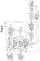
- step is represented by "S.”
- the ⁇ N torque calculation section 53 first calculates a throttle opening lower-limit threshold ⁇ 0 and a throttle opening upper-limit threshold ⁇ 1 on the basis of the vehicle speed V fed from the vehicle speed calculation section 52 (S101). At this time, the microcomputer 32 refers to a throttle opening threshold map Mk shown in FIG 5.
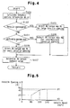
- FIG. 5 shows the throttle opening threshold map Mk in the form of a graph wherein the horizontal axis represents vehicle speed V (km/h) and the vertical axis represents throttle opening ⁇ (%).
- the throttle opening lower-limit threshold ⁇ 0 is defined to be 2% (constant) irrespective of vehicle speed V.
- the throttle opening upper-limit threshold ⁇ 1 is defined to be 20% (constant) when the vehicle speed V is 0 to 60 km/h (low speed range), to increase from 20 to 40% when the vehicle speed V is 60 to 100 km/h (intermediate speed range), to increase from 40 to 50% when the vehicle speed V is 100 to 140 km/h (high speed range), and to be 50% (constant) when the vehicle speed V is greater than 140 km/h (this range being included in the high speed range).
- the ⁇ N torque calculation section 53 determines whether the throttle opening ⁇ detected by the throttle opening sensor 34 is not less than the throttle opening upper-limit threshold ⁇ 1 obtained in S101 (S102).
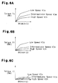
- the ⁇ N torque calculation section 53 uses a ⁇ N torque map Ml for large throttle opening shown in FIG. 6A (S103), and calculates the ⁇ N torque T1 with reference to the ⁇ N torque map Ml (S107).
- the ⁇ N torque map Ml for large throttle opening shown in FIG 6A is used in the case where the throttle opening ⁇ is large (i.e., a driver desires a large torque) and the differential rotational speed ⁇ N is large, such as at the time of uphill climbing or starting, or is used to improve the steerability in the case where the accelerator pedal is depressed by a large amount during cornering.
- the ⁇ N torque map Ml is previously stored in the ROM 32a.
- the ⁇ N torque map Ml defines the relation between differential rotational speed ⁇ N (min -1 ) (the horizontal axis in the graph shown in FIG. 6A) and ⁇ N torque T1 (Nm) (the vertical axis in the graph shown in FIG. 6A).
- the ⁇ N torque map Ml includes a map curve VIs to be used when the vehicle speed V is in a low speed range (0 to 60 km/h), a map curve Vlm to be used when the vehicle speed V is in an intermediate speed range (60 to 100 km/h), and a map curve Vlh to be used when the vehicle speed V is in a high speed range (100 km/h or higher).
- Each of the map curves Vls, Vlm, and Vlh represents a change in the ⁇ N torque T1 with an increase in the differential rotational speed ⁇ N.
- the ratio of increase in the ⁇ N torque T1 to that in the differential rotational speed ⁇ N is set for each of the low, intermediate, and high speed ranges in such a manner that the ratio is the largest in the low speed range, decreases in the intermediate speed range, and decreases further in the high speed range.
- the map curve Vlm is located between the map curve Vls and the map curve Vlh.
- the ⁇ N torque map Ml has the following characteristics. As shown by the map curves Vls, Vlm, and Vlh, as the differential rotational speed ⁇ N increases, the ⁇ N torque T1 increases sharply until the differential rotational speed ⁇ N reaches a predetermined value, and then increases gradually.
- the ⁇ N torque T1 is properly determined so as to prevent occurrence of a problems such that the steering characteristics shifts excessively to the under-steer side, or the entire vehicle body is pushed outward from an intended cornering path. Therefore, steerablity at the time of large throttle opening can be secured.
- the ⁇ N torque calculation section 53 determines whether the throttle opening ⁇ detected by the throttle opening sensor 34 is not less than the throttle opening lower-limit threshold ⁇ 0 and less than the throttle opening upper-limit threshold ⁇ 1.
- the ⁇ N torque calculation section 53 uses a ⁇ N torque map Mm for intermediate throttle opening shown in FIG. 6B (S105), and calculates the ⁇ N torque T1 with reference to the ⁇ N torque map Mm (S107).
- the ⁇ N torque map Mm for intermediate throttle opening shown in FIG 6B is used in the case of, for example, ordinary straight travel, in which there is not required a large ⁇ N torque T1 (engagement force) as is required in the case of uphill climbing or starting.
- the ⁇ N torque map Mm is previously stored in the ROM 32a.
- the ⁇ N torque map Mm for intermediate throttle opening has a configuration similar to that of the ⁇ N torque map Ml for large throttle opening.
- the ratio of increase in the ⁇ N torque T1 to that in the differential rotational speed ⁇ N in the ⁇ N torque map Mm is set to be smaller than that in the ⁇ N torque map Ml for large throttle opening.
- the inclinations (the increase gradients of the ⁇ N torque T1) of the map curves Vls, Vlm, and Vlh of the ⁇ N torque map Mm for intermediate throttle opening are set slightly smaller than those of the map curves Vls, Vlm, and Vlh of the ⁇ N torque map Ml for large throttle opening.
- the ⁇ N torque calculation section 53 uses a ⁇ N torque map Ms for small throttle opening shown in FIG 6C (S106), and calculates the ⁇ N torque T1 with reference to the ⁇ N torque map Ms (S107).
- the ⁇ N torque map Ms for small throttle opening shown in FIG. 6C is used in the case where the depression amount of the accelerator pedal decreases during cornering, and is previously stored in the ROM 32a.
- the ⁇ N torque map Ms has a configuration similar to that of the ⁇ N torque map Mm.
- the ratio of increase in the ⁇ N torque T1 to that in the differential rotational speed ⁇ N in the ⁇ N torque map Ms is set to be smaller than that in the ⁇ N torque map Mm for intermediate throttle opening.
- the inclinations (the increase gradients of the ⁇ N torque T1) of the map curves Vls, Vlm, and Vlh of the ⁇ N torque map Ms for small throttle opening are set smaller than those of the map curves Vls, Vlm, and Vlh of the ⁇ N torque map Mm for intermediate throttle opening.
- the ⁇ N torque map Ms has the following characteristics. As shown by the map curves Vls, Vlm, and Vlh, as the differential rotational speed ⁇ N increases, the ⁇ N torque T1 increases slowly until the differential rotational speed ⁇ N reaches a predetermined value, and then is maintained substantially constant.
- the ⁇ N torque T1 is determined properly in order to prevent unsatisfactory vehicle behavior such as occurrence of an excessive tack-in phenomenon in which the vehicle turns inward sharply or outward drift of the rear of the vehicle. Therefore, the motion stability of the vehicle at the time of small throttle opening is improved, and the traveling stability of the four-wheel-drive vehicle 11 is secured.
- the microcomputer 32 repeats the processing steps S101 to S107 at predetermined control intervals.
- the ⁇ N torque calculation section 53 selectively uses the ⁇ N torque maps Ml, Mm, and Ms in accordance with the traveling conditions of the four-wheel-drive vehicle 11 (e.g., a torque or acceleration that the driver desires and that can be determined on the basis of the throttle opening ⁇ ).
- the traveling conditions of the four-wheel-drive vehicle 11 e.g., a torque or acceleration that the driver desires and that can be determined on the basis of the throttle opening ⁇ .
- the ⁇ N torque map Ml for large throttle opening serves as a first drive force map whose characteristics are determined while priority is placed on the steerability of the vehicle.
- the ⁇ N torque map Ms for small throttle opening serves as a second drive force map whose characteristics are determined while priority is placed on motion stability of the vehicle in such a manner that the gradient of increase of ⁇ N torque T1 (drive-force increase gradient) is smaller than that in the AN torque map Ml for large throttle opening.
- the ⁇ N torque map Mm for intermediate throttle opening serves as a third drive force map whose characteristics are determined in such a manner that the gradient of increase of ⁇ N torque T1 (drive-force increase gradient) falls between that in the ⁇ N torque map Ml for large throttle opening and that in the ⁇ N torque map Ms for small throttle opening.
- the overall structure of the four-wheel-drive vehicle, the structure of the drive-force transmission apparatus, and the electrical configuration are identical with those in the first embodiment, and therefore their repeated descriptions are omitted.
- the microcomputer 32 performs drive-force distribution control as follows.
- the wheel speeds Vfl, Vfr, Vrl, and Vrr of the left and right front wheels and the left and right rear wheels detected by the wheel speed sensors 33 are fed to a differential-rotational-speed calculation section (hereinafter referred to as the " ⁇ N calculation section") 51 and a vehicle-speed calculation section 52.
- the vehicle-speed calculation section 52 calculates a vehicle speed V.
- the vehicle-speed calculation section 52 feeds the calculated vehicle speed V to a differential-rotational-speed torque calculation section (hereinafter referred to as the " ⁇ N torque calculation section") 53 and a pre-torque calculation section 54.
- the vehicle-speed calculation section 52 serves as vehicle-speed detection means.
- the throttle opening ⁇ detected by the throttle opening sensor 34' is input to the ⁇ N torque calculation section 53.
- the ⁇ N torque calculation section 53 calculates a transmission torque corresponding to the vehicle speed V and the differential rotational speed ⁇ N (hereinafter referred to as " ⁇ N torque T1") with reference to a differential-rotational-speed-to-torque map (hereinafter referred to as the " ⁇ N torque map").
- the ⁇ N torque map defines a change in the ⁇ N torque T1 with an increase in the differential rotational speed ⁇ N for each of a plurality of vehicle speed ranges.
- the ⁇ N torque calculation section 53 feeds the calculated ⁇ N torque T1 to an adder 55.
- the throttle opening ⁇ detected by the throttle opening sensor 34 is input to the pre-torque calculation section 54.
- the pre-torque calculation section 54 calculates a transmission torque corresponding to the throttle opening ⁇ and the vehicle speed V (hereinafter referred to as "pre-torque T2") with reference to a pre-torque map.
- the pre-torque map defines a change in the pre-torque T2 with an increase in the throttle opening ⁇ for each of a plurality of vehicle speed ranges.
- the pre-torque calculation section 54 feeds the calculated pre-torque T2 to the adder 55.
- the calculation of the pre-torque T2 by the pre-torque calculation section 54 will be described later.
- the adder 55 feeds the calculated command torque T to a command current calculation section 56.
- the command current calculation section 56 calculates current corresponding to the command torque T fed from the adder 55 (hereinafter referred to as the "base command current I0") with reference to a base command current map.
- the base command current map is used to convert the command torque T to the base command current I0 and defines a change in the command torque T with a change in current supplied to the electromagnetic coil 22.
- the command current calculation section 56 corrects the base command current I0 in accordance with a correction coefficient corresponding to the vehicle speed V and feeds the corrected base command current I0 to a subtracter 57.
- coil current Ic of the electromagnetic coil 22 detected by the current detection circuit 36 is input to the subtracter 57.
- the PI control section 58 calculates a PI control value on the basis of the current deviation ⁇ I fed from the subtracter 57, and feeds the PI control value to a PWM (pulse width modulation) to an output conversion section 59.
- the PWM output conversion section 59 performs PWM calculation in accordance with the received PI control value, and feeds the results of the PWM calculation to the drive circuit 37.
- the drive circuit 37 supplies current to the electromagnetic coil 22 of the electromagnetic clutch mechanism 21.
- the clutch plates of the electromagnetic clutch mechanism 21 frictionally engage with one another with an engagement force corresponding to the supplied coil current.
- the microcomputer 32 optimally controls torque transmission between the front wheels 16 and the rear wheels 20 by variably controlling the base command current I0 in accordance with the differential rotational speed ⁇ N, the vehicle speed V, and the throttle opening ⁇ (acceleration operation amount); i.e., in accordance with the traveling state of the vehicle.
- the pre-torque calculation section 54 of the microcomputer 32 calculates a throttle open speed Vs on the basis of the throttle opening ⁇ sent from the throttle opening sensor 34 (S201). Specifically, the pre-torque calculation section 54 calculates a change in the throttle opening ⁇ during each interval of 100 ms; i.e., a differential value of the throttle opening ⁇ .
- the pre-torque calculation section 54 determines whether the thus-calculated throttle open speed Vs is greater than a threshold Vs0 (5%/100 ms in the present embodiment) (S202).
- the pre-torque calculation section 54 selects a pre-torque map configured to determine a command torque from the throttle opening ⁇ and the vehicle speed V (hereinafter, this pre-torque map will be referred to as the "normal map Mpn") (S203), and then processing proceeds to S204.
- the pre-torque calculation section 54 calculates the pre-torque T2 on the basis of the throttle opening ⁇ and the vehicle speed V and with reference to the normal map Mpn.
- the normal map Mpn is used for ordinary driving in which the driver does not depress the accelerator pedal abruptly as in the case of abrupt starting or acceleration while climbing uphill, and is previously stored in the ROM 32a.
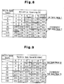
- the normal map Mpn is a table for determining the pre-torque T2 from the throttle opening ⁇ and the vehicle speed V.
- a pre-torque (command torque) T2 is defined for each of combinations between different values (0, 1, 5, 20, 70, 100) of the throttle opening ⁇ and different values (0, 5, 20, 30, 60, 130, 150) of the vehicle speed V.
- the pre-torque T2 is obtained through linear interpolation.
- the pre-torque calculation section 54 determines in step S202 that throttle open speed Vs is greater than the threshold Vs0 (5%/100 ms) (YES in S202)
- the pre-torque calculation section 54 selects a pre-torque map configured to determine a command torque from the throttle open speed Vs and the vehicle speed V (hereinafter, this pre-torque map will be referred to as the "alternative map Mps") (S205), and processing proceeds to S204.
- the pre-torque calculation section 54 calculates the pre-torque T2 on the basis of the throttle open speed Vs and the vehicle speed V and with reference to the alternative map Mps.
- the alternative map Mps is used for the case in which the driver depresses the accelerator pedal abruptly at the time of, for example, abrupt starting or acceleration when climbing uphill, and is previously stored in the ROM 32a.
- the alternative map Mps is a table for determining the pre-torque T2 from the throttle open speed Vs and the vehicle speed V.
- a pre-torque (command torque) T2 is defined for each of combinations between different values (5, 7, 10, 12, 15, 20) of the throttle open speed Vs and different values (0, 5, 20, 30, 60, 130, 150) of the vehicle speed V.
- the pre-torque T2 is obtained through linear interpolation.
- Values of command torque for a low speed range L* in the alternative map Mps are set to be smaller than corresponding values of command torque for a low speed range L in the normal map Mpn (see FIG 8).
- the values of command torque for the low speed range L ⁇ in the alternative map Mps are about half the corresponding values of command torque for the low speed range L in the normal map Mpn.
- Values of command torque for an intermediate-high speed range H ⁇ in the alternative map Mps are set to be greater than corresponding values of command torque for an intermediate-high speed range H in the normal map Mpn (see FIG. 8).
- the values of command torque for the intermediate-high speed range H* in the alternative map Mps are about 1.5 times the corresponding values of command torque for the intermediate-high speed range H in the normal map Mpn.
- the normal map Mpn shown in FIG 8 is compared with the alternative map Mps shown in FIG. 9. Since the throttle opening ⁇ is used as a parameter in the normal map Mpn, whereas the throttle open speed Vs is used as a parameter in the alternative map Mps, the comparison is performed as follows. First, a throttle open speed Vs is obtained from the normal map Mpn, and a command torque corresponding to the throttle open speed Vs is obtained. Subsequently, the thus-obtained command torque is compared with a command torque which is obtained from the alternative map Mps and which corresponds to the throttle open speed Vs.
- values of command torque for the low speed range L in the normal map Mpn are compared with values of command torque for the low speed range L* in the alternative map Mps.
- the throttle open speed Vs (i.e., the differential value of the throttle opening ⁇ ) can be obtained by the following Expression (A).
- Vs d ⁇ /dt where d ⁇ represents variation in the throttle opening ⁇ per unit time (control period), and dt represents a control period (sampling period).
- the throttle open speed Vs is calculated to be 15%/100 ms, and the command torque dT corresponding to the calculated throttle open speed Vs is 0 Nm.
- the alternative map Mps is used, whereby the base command current I0 supplied to the electromagnetic clutch mechanism 21 (i.e., the torque transmitted to the rear wheels) decreases as compared with the case in which the normal map Mpn is used. Therefore, shock that is generated upon engagement of the clutch at the time of abrupt starting can be mitigated.
- the alternative map Mps is used, whereby the base command current I0 supplied to the electromagnetic clutch mechanism 21 (i.e., the torque transmitted to the rear wheels) increases as compared with the case in which the normal map Mpn is used. Therefore, when a driver desires a sensation of strong torque or stability in the state in which the vehicle travels uphill at a speed in the intermediate-high speed range, the driver can obtain a sensation of strong torque or stability by depressing the accelerator pedal by only a small amount.
- the microcomputer 32 repeats the processing steps S201 to S205 at predetermined control intervals (sampling intervals).
- control intervals are set to 100 ms.
- the overall structure of the four-wheel-drive vehicle, the structure of the drive-force transmission apparatus, and the electrical configuration are identical with those in the first embodiment, and therefore, their repeated descriptions are omitted.
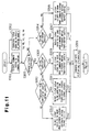
- various functions of the microcomputer 32 which are realized through execution of the various control programs stored in the ROM 32a will be described with reference to the functional block diagram shown in FIG. 10.
- various parameters such as wheel speeds Vfl, Vfr, Vrl, Vrr, throttle opening ⁇ , and differential rotational speed ⁇ N, refer to corresponding signals.
- the microcomputer 32 performs drive-force distribution control as follows.
- the wheel speeds Vfl, Vfr, Vrl, and Vrr of the left and right front wheels 16 and the left and right rear wheels 20 detected by the wheel speed sensors 33 are fed to a differential-rotational-speed calculation section (hereinafter referred to as the " ⁇ N calculation section") 151, a tight-corner determination section 152, and a vehicle-speed calculation section 153.
- ⁇ N calculation section differential-rotational-speed calculation section
- the tight corner determination section 152 determines whether the four-wheel-drive vehicle 11 is traveling along a tight corner; i.e., is in a tight-corner traveling state. Specifically, the tight comer determination section 152 calculates a rotational speed difference between the outside front wheel 16 and the inside rear wheel 20 on the basis of the wheel speeds Vfl, Vfr, Vrl, and Vrr output from the wheel speed sensors 33. When the calculated rotational speed difference is smaller than a previously set threshold, the tight comer determination section 152 judges that the vehicle 11 is in the tight-corner traveling state. When the calculated rotational speed difference is greater than the previously set threshold, the tight comer determination section 152 judges that the vehicle 11 is not in the tight-corner traveling state, but is in a normal traveling state.
- the threshold is determined as follows. A rotational speed difference which is produced between the outside front wheel and the inside rear wheel when the vehicle turns with a turning radius which causes a tight-corner braking phenomenon (a phenomenon in which braking torque acts on the drive wheels (the front wheels in the present embodiment) attributed to a difference in average turning radius between the front and rear wheels during cornering) is obtained through an experiment or theoretical calculation, and the threshold is determined on the basis of the thus-obtained rotational speed difference.
- the tight corner determination section 152 feeds the result of tight-comer determination to the command torque calculation section 154 and the command current calculation section 155.
- the vehicle-speed calculation section 153 which serves as vehicle-speed detection means, calculates a vehicle speed V on the basis of the received wheel speeds Vfl, Vfr, Vrl, and Vrr.
- the vehicle-speed calculation section 153 feeds the calculated vehicle speed V to the command torque calculation section 154 and the command current calculation section 155.
- the throttle opening ⁇ detected by the throttle opening sensor 34 is input to the command torque calculation section 154.
- the command torque calculation section 154 which serves as command torque calculation means, calculates transmission torque ( ⁇ N torque) corresponding to the differential rotational speed ⁇ N, the result of tight-corner determination, and the vehicle speed V, with reference to a differential-rotational-speed-to-torque map (hereinafter referred to as the " ⁇ N torque map").
- the ⁇ N torque map defines a change in the ⁇ N torque with an increase in the differential rotational speed ⁇ N for each of a plurality of vehicle speed ranges.
- two types of ⁇ N torque maps i.e., a ⁇ N torque map for normal travel and a ⁇ N torque map for tight-corner travel, are previously stored in the ROM 32a.
- the command torque calculation section 154 calculates a transmission torque (pre-torque) corresponding to the throttle opening ⁇ and the vehicle speed V with reference to a pre-torque map.
- the pre-torque map defines a change in the pre-torque with an increase in the throttle opening ⁇ for each of a plurality of vehicle speed ranges.
- two types of pre-torque maps i.e., a pre-torque map for normal travel and a pre-torque map for tight-corner travel, are previously stored in the ROM 32a.
- the command torque calculation section 154 adds the ⁇ N torque to the calculated pre-torque to thereby obtain a command torque T, and feeds the thus-obtained command torque T to a command current calculation section 155, which serves as command current calculation means.
- the command current calculation section 155 calculates a base command current I0 on the basis of the vehicle speed V from the vehicle-speed calculation section 153 and the command torque T from the command torque calculation section 154. Specifically, the command torque T from the command torque calculation section 154 is input to a command-torque- to-command-current conversion section 156; and the vehicle speed V from the vehicle-speed calculation section 153 is input to a filter value calculation section 157.
- the command-torque-to-command-current conversion section 156 calculates current (base command current 10) corresponding to the command torque T from the command torque calculation section 154, with reference to a base command current map.
- the base command current map is used to convert the command torque T to the base command current I0 and defines a change in the command torque T with a change in current supplied to the electromagnetic coil 22.
- the command-torque-to-command-current conversion section 156 feeds the calculated base command current I0 to a command current filter section 158.
- the filter value calculation section 157 calculates a command current filter value ⁇ corresponding to the vehicle speed V with reference to a command current filter map of a vehicle-speed response type.
- the command current filter map defines a change in the command current filter value ⁇ (time constant) with an increase in the vehicle speed V.
- a plurality of command current filter maps having different characteristics are stored in the ROM 32a. Each command current filter map is provided for an assumed vehicle traveling state.
- the filter value calculation section 157 calculates a plurality of command current filter values ⁇ on the basis of the vehicle speed V with reference to the individual command current filter maps.
- the filter value calculation section 157 feeds the calculated command current filter values ⁇ to the command current filter section 158.
- the command current filter section 158 selects one of the command current filter values ⁇ on the basis of the a change (increase/decrease) in the base command current I0 and the result of tight-comer determination from the tight corner determination section 152 (i.e., the control state of the vehicle). Specifically, the command current filter section 158 selects an optimal command current filter value ⁇ corresponding to the present traveling state. The command current filter section 158 filters the base command current I0 by use of the selected command current filter value ⁇ , and feeds the filtered base command current I0 to a subtracter 159.
- command current calculation section 155 The calculation of command current by the command current calculation section 155 will be described later.
- coil current Ic current flowing through the electromagnetic coil 22 detected by the current detection circuit 36 is input to the subtracter 159.
- the PI control section 160 calculates a PI control value on the basis of the current deviation ⁇ I fed from the subtracter 159, and feeds the PI control value to a PWM (pulse width modulation) output conversion section 161.
- the PWM output conversion section 161 performs PWM calculation in accordance with the received PI control value, and feeds the results of the PWM calculation to the drive circuit 37.
- the drive circuit 37 supplies current to the electromagnetic coil 22 of the electromagnetic clutch mechanism 21.
- the clutch plates of the electromagnetic clutch mechanism 21 frictionally engage with one another with an engagement force corresponding to the supplied coil current.
- the microcomputer 32 grasps the traveling state of the vehicle on the basis of the wheel speeds Vfl, Vfr, Vrl, and Vrr and the throttle opening ⁇ , and variably controls the base command current I0 in accordance with the traveling state, to thereby optimally control torque transmission between the front wheels 16 and the rear wheels 20.
- a speed range of 0 to 30 km/h is called a low speed range
- a speed range of 30 to 60 km/h is called an intermediate speed range
- a speed range of 60 km/h or greater is called a high speed range.
- normal control refers to controls other than tight-corner control; i.e., controls which are performed when the vehicle travels along roads other than tight comers.
- the command-torque-to-command-current conversion section 156 of the command current calculation section 155 first calculates current (base command current 10) corresponding to the command torque T fed from the command torque calculation section 154, with reference to the base command current map (S301).
- the filter value calculation section 157 of the command current calculation section 155 calculates command current filter values ⁇ on the basis of the vehicle speed V (S302).
- the filter value calculation section 157 calculates a command current filter value ⁇ corresponding to the vehicle speed V with reference to each of command current filter maps Ma, Mb, Mc, Md, and Me of a vehicle-speed responsive type, which are previously stored in the ROM 32a and are shown in FIGS. 12A to 12E.
- the command current filter values ⁇ calculated with reference to the command current filter maps Ma, Mb, Mc, Md, and Me are denoted by ⁇ a, ⁇ b, ⁇ c, ⁇ d, and ⁇ e, respectively.
- the calculated command current filter values ⁇ a, ⁇ b, ⁇ c, ⁇ d, and ⁇ e are fed the command current filter section 158.
- the command current filter value ⁇ is a time constant which represents the time by which the actual current (response) reaches 63.2% the command current (target value).
- the time required for the actual current (the coil current Ic in the present embodiment) to reach the command current (the base command current 10 in the present embodiment) is adjusted on the basis of the command current filter value ⁇ ; i.e., the time constant.
- FIGS. 12A to 12E which show command current filter maps Ma, Mb, Mc, Md, and Me, respectively, the horizontal axis represents vehicle speed V (km/h), and the vertical axis represents command current filter value ⁇ (sec).
- the command current filter maps Ma, Mb, Mc, Md, and Me define respective changes in the command current filter values ⁇ a, ⁇ b, ⁇ c, ⁇ d, and ⁇ e with an increase in the vehicle speed V.
- the command current filter map Ma shown in FIG. 12A is used to obtain a command current filter value ⁇ a in the case where the base command current 10 tends to increase from the previous value during normal control.
- the command current filter map Ma has the following characteristics.
- the command current filter value ⁇ a is constant irrespective of the vehicle speed V.
- the command current filter value ⁇ a is set so as to attain response speed. Therefore, responsiveness (response speed) of the coil current Ic can be secured in the low, intermediate, and high speed ranges.
- the command current filter map Mb shown in FIG. 12B is used to obtain a command current filter value ⁇ b in the case where the base command current I0 tends to decrease from the previous value during normal control.
- the command current filter map Mb has the following characteristics.
- the command current filter value ⁇ b is ⁇ b1 (constant) when the vehicle speed V is 0 to V1, increases from ⁇ b1 to ⁇ b2 when the vehicle speed V increases from V1 to V2, and is ⁇ b2 (constant) when the vehicle speed V is V2 or higher.
- the ⁇ b1 is set to a value which enables obtainment of some degree of responsiveness without lowering the motion stability of the vehicle.
- ⁇ b2 is set while priority is placed on the motion stability of the vehicle, in such a manner that the command current does not change abruptly.
- V1 is a speed in the low speed range
- V2 is a speed in the low speed range or the intermediate speed range. Therefore, use of the command current filter value ⁇ b suppresses abrupt change in the coil current Ic, which change would otherwise occur at the time of transition from the low speed range to the intermediate speed range.
- the command current filter map Mc shown in FIG. 12C is used to obtain a command current filter value ⁇ c in the case where the base command current I0 tends to increase from the previous value during fight-corner control.
- the command current filter map Mc has the following characteristics.
- the command current filter value ⁇ c is ⁇ c2 (constant) when the vehicle speed V is 0 to V1, decreases from ⁇ c2 to ⁇ c1 when the vehicle speed V increases from V1 to V2, and is ⁇ c1 (constant) when the vehicle speed V is V2 or higher.
- the ⁇ c1 is set to a value which enables obtainment of some degree of responsiveness without lowering the motion stability of the vehicle.
- ⁇ c2 is set to a value which prevents abrupt change in the command current and enables obtainment of some degree of responsiveness.
- V1 is a speed in the low speed range
- V2 is a speed in the low speed range or the intermediate speed range. Therefore, when the command current filter value ⁇ c is used, in the low speed range, abrupt change in the coil current Ic is suppressed, and in the,intermediate and high speed ranges, the responsiveness (response speed) of the coil current Ic can be secured to a degree such that the motion stability of the vehicle is not impaired.
- the command current filter map Md shown in FIG. 12D is used to obtain a command current filter value ⁇ d in the case where the base command current I0 tends to decrease from the previous value during tight-corner control.
- the command current filter map Md has the following characteristics.
- the command current filter value ⁇ d is constant irrespective of the vehicle speed V.
- the command current filter value ⁇ d is set to a value which enables obtainment of some degree of responsiveness without lowering the motion stability of the vehicle. Therefore, when the command current filter value ⁇ d is used, in the low, intermediate, and high speed ranges, the responsiveness (response speed) of the coil current Ic can be secured to a degree such that the motion stability of the vehicle is not impaired.
- the command current filter map Me shown in FIG. 12E is used to obtain a command current filter value ⁇ e in the case where the base command current 10 tends to increase from the previous value when tight-corner control is switched to normal control.
- the command current filter map Me has the following characteristics.
- the command current filter value ⁇ e is ⁇ e2 (constant) when the vehicle speed V is 0 to V1, decreases from ⁇ e2 to ⁇ e1 when the vehicle speed V increases from V1 to V2, and is ⁇ e1 (constant) when the vehicle speed V is V2 or higher.
- ⁇ e1 is set to a value which enables obtainment of some degree of responsiveness without lowering the motion stability of the vehicle.
- ⁇ e2 is set to a value which prevents abrupt change in the command current and enables obtainment of some degree of responsiveness.
- V1 is a speed in the low speed range
- V2 is a speed in the low speed range or the intermediate speed range. Therefore, when the command current filter value ⁇ e is used, in the low speed range, abrupt change in the coil current Ic is suppressed, and in the intermediate and high speed ranges, the responsiveness (response speed) of the coil current Ic can be secured to a degree such that the motion stability of the vehicle is not impaired.
- the command current filter section 158 of the command current calculation section 155 compares the base command current I0 obtained in S301 with the previous value (the previous base command current I0 after having undergone the filtering processing) (S303).
- the command current filter section 158 determines whether the tight-corner control is being performed.
- the command current filter section 158 selects the command current filter value ⁇ b obtained with reference to the command current filter map Mb and suitable for use when the command current tends to decrease during normal control (S305). Subsequently, processing of the command current filter section 158 proceeds to S306.
- the command current filter section 158 filters the base command current 10 on the basis of the command current filter value ⁇ b.
- the command current filter value ⁇ b in the low speed range, shock and noise generated upon engagement operation of the electromagnetic clutch mechanism 21 are suppressed, and in the intermediate and high speed ranges, the coil current Ic decreases slowly as compared with that in the low speed range, whereby the electromagnetic clutch mechanism 21 is operated smoothly. Further, during transition from the low speed range to the intermediate speed range, abrupt change (increase/decrease) in the coil current Ic is suppressed, whereby the motion stability of the vehicle is secured.
- the command current filter section 158 selects the command current filter value ⁇ d obtained with reference to the command current filter map Md and suitable for use when the command current tends to decrease during tight-corner control (S307). Subsequently, processing of the command current filter section 158 proceeds to S306.
- the command current filter section 158 filters the base command current I0 on the basis of the command current filter value ⁇ d.
- the responsiveness (response speed) of the coil current Ic is secured to some degree, and steerablity and the motion stability of the vehicle are secured.
- the command current filter section 158 determines whether the tight-corner control is being performed.
- the command current filter section 158 selects the command current filter value ⁇ c obtained with reference to the command current filter map Mc and suitable for use when the command current tends to increase during tight-corner control (S309). Subsequently, processing of the command current filter section 158 proceeds to S306.
- the command current filter section 158 filters the base command current I0 on the basis of the command current filter value ⁇ c.
- the command current filter value ⁇ c in the low speed range, shock and noise generated upon engagement operation of the electromagnetic clutch mechanism 21 are suppressed, and in the intermediate and high speed ranges, the responsiveness of the coil current Ic is enhanced to a degree such that the motion stability of the vehicle is not impaired. Further, during transition from the low speed range to the intermediate speed range, abrupt change in the coil current Ic is suppressed, whereby the motion stability of the vehicle is secured.
- the command current filter section 158 determines whether switching from tight-corner control to normal control is being performed.
- the command current filter section 158 determines that switching from tight-corner control to normal control is being performed (YES in S310)
- the command current filter section 158 selects the command current filter value ⁇ e obtained with reference to the command current filter map Me and suitable for use when the command current tends to increase during switching or transition from the tight-corner control to the normal control (S311). Subsequently, processing of the command current filter section 158 proceeds to S306.
- the command current filter section 158 filters the base command current 10 on the basis of the command current filter value ⁇ e.
- the command current filter value ⁇ e in the low speed range, shock and noise generated upon engagement operation of the electromagnetic clutch mechanism 21 are suppressed, and in the intermediate and high speed ranges, the responsiveness of the coil current Ic is enhanced to a degree such that the motion stability of the vehicle is not impaired. Further, during transition from the low speed range to the intermediate speed range, abrupt change in the coil current Ic is suppressed, whereby the motion stability of the vehicle is secured.
- the command current filter section 158 determines that the switching from tight-corner control to normal control is not being performed (NO in S310)
- the command current filter section 158 selects the command current filter value ⁇ a obtained with reference to the command current filter map Ma and suitable for use when the command current tends to increase during normal control (S312). Subsequently, the command current filter section 158 proceeds to S306.
- the command current filter section 158 filters the base command current I0 on the basis of the command current filter value ⁇ a. Through application of the command current filter value ⁇ a, in the low, intermediate, and high speed ranges, high responsiveness (response speed) of the coil current Ic is secured.
- the third embodiment may be modified as follows.
- a drive-force distribution controller controls a drive-force transmission apparatus of a vehicle in order to control transmission of drive force to rear wheels or front wheels of the vehicle in accordance with a designated drive-force transmission ratio.
- the drive-force transmission ratio is changed on the basis of vehicle speed, differential rotational speed (speed difference between the front and rear wheels), and throttle opening.
- the drive-force transmission ratio is changed on the basis of vehicle speed, throttle opening, and throttle open speed.
- the change speed of current which is supplied to the drive-force transmission apparatus in order to control the drive-force transmission ratio is adjusted in accordance with a command current filter value which is determined on the basis of vehicle speed and a command current filter map of a vehicle-speed responsive type.
Landscapes
- Engineering & Computer Science (AREA)
- Chemical & Material Sciences (AREA)
- Combustion & Propulsion (AREA)
- Transportation (AREA)
- Mechanical Engineering (AREA)
- Arrangement And Driving Of Transmission Devices (AREA)
Applications Claiming Priority (6)
| Application Number | Priority Date | Filing Date | Title |
|---|---|---|---|
| JP2002126220 | 2002-04-26 | ||
| JP2002126961A JP3753094B2 (ja) | 2002-04-26 | 2002-04-26 | 四輪駆動車の駆動力配分制御装置 |
| JP2002126961 | 2002-04-26 | ||
| JP2002126220A JP3798728B2 (ja) | 2002-04-26 | 2002-04-26 | 四輪駆動車の駆動力配分制御装置 |
| JP2002126960 | 2002-04-26 | ||
| JP2002126960A JP3798729B2 (ja) | 2002-04-26 | 2002-04-26 | 四輪駆動車の駆動力配分制御装置 |
Publications (3)
| Publication Number | Publication Date |
|---|---|
| EP1359046A2 true EP1359046A2 (de) | 2003-11-05 |
| EP1359046A3 EP1359046A3 (de) | 2004-02-04 |
| EP1359046B1 EP1359046B1 (de) | 2006-06-14 |
Family
ID=29219474
Family Applications (1)
| Application Number | Title | Priority Date | Filing Date |
|---|---|---|---|
| EP03009320A Expired - Lifetime EP1359046B1 (de) | 2002-04-26 | 2003-04-24 | Verfahren und System zur Antriebskraftverteilung für ein Kraftfahrzeug mit Allradantrieb |
Country Status (3)
| Country | Link |
|---|---|
| US (1) | US6873896B2 (de) |
| EP (1) | EP1359046B1 (de) |
| DE (1) | DE60306024T2 (de) |
Cited By (2)
| Publication number | Priority date | Publication date | Assignee | Title |
|---|---|---|---|---|
| EP1728672A3 (de) * | 2005-05-30 | 2012-11-28 | Hitachi, Ltd. | Vorrichtung zur Steuerung eines hybrid vierradangetriebenen Fahrzeugs |
| EP2551159A1 (de) * | 2011-07-28 | 2013-01-30 | Mazda Motor Corporation | Steuerverfahren und Steuervorrichtung für Fahrzeug mit Allradantrieb |
Families Citing this family (18)
| Publication number | Priority date | Publication date | Assignee | Title |
|---|---|---|---|---|
| JP4317716B2 (ja) * | 2003-07-08 | 2009-08-19 | 株式会社ジェイテクト | 4輪駆動車の駆動力配分制御装置 |
| JP4554252B2 (ja) * | 2004-03-31 | 2010-09-29 | 本田技研工業株式会社 | 4輪駆動車両の制御方法 |
| JP2006299856A (ja) * | 2005-04-18 | 2006-11-02 | Mitsubishi Electric Corp | 内燃機関の電子スロットル制御装置 |
| WO2007035136A1 (en) * | 2005-09-20 | 2007-03-29 | Volvo Construction Equipment Holding Sweden Ab | A method for controlling rotation speed |
| US7614470B2 (en) * | 2005-10-11 | 2009-11-10 | Borgwarner, Inc. | Torque proportioning control system |
| US7473209B2 (en) * | 2006-08-09 | 2009-01-06 | Ford Global Technologies, Llc | Torque based transfer case control |
| JP5038837B2 (ja) * | 2007-10-01 | 2012-10-03 | 富士重工業株式会社 | 車両のタックイン防止制御装置 |
| US7784686B2 (en) * | 2007-12-27 | 2010-08-31 | Target Brands, Inc. | Transaction card with enclosed chamber |
| JP5098736B2 (ja) * | 2008-03-25 | 2012-12-12 | 株式会社明電舎 | 車両速度制御装置 |
| US7813865B2 (en) * | 2008-11-13 | 2010-10-12 | Ford Global Technologies, Llc | Torque-based hybrid electric vehicle powertrain control system and method |
| DE102009031500B4 (de) * | 2009-07-02 | 2021-12-30 | Magna powertrain gmbh & co kg | Vorrichtung und Verfahren zum Steuern einer Allradkupplung |
| JP5526983B2 (ja) * | 2010-04-28 | 2014-06-18 | 日産自動車株式会社 | 車両の操舵時挙動改善装置 |
| JP5413295B2 (ja) | 2010-04-28 | 2014-02-12 | 日産自動車株式会社 | 車両の操舵時挙動改善装置 |
| US8886408B2 (en) | 2012-01-30 | 2014-11-11 | Honda Motor Co., Ltd. | Vehicle steering control system and method |
| US8918263B2 (en) | 2013-03-14 | 2014-12-23 | Clark Equipment Company | Traction control for power machine |
| JP5837022B2 (ja) * | 2013-03-28 | 2015-12-24 | 本田技研工業株式会社 | 四輪駆動車両の駆動力配分制御装置 |
| WO2017073184A1 (ja) * | 2015-10-26 | 2017-05-04 | 三菱電機株式会社 | 車速制御装置 |
| JP6919349B2 (ja) * | 2017-06-09 | 2021-08-18 | 株式会社アイシン | 走行支援システム |
Family Cites Families (13)
| Publication number | Priority date | Publication date | Assignee | Title |
|---|---|---|---|---|
| JPS6212422A (ja) * | 1985-07-09 | 1987-01-21 | Nissan Motor Co Ltd | 4輪駆動車の駆動力配分制御装置 |
| US4773500A (en) * | 1985-09-13 | 1988-09-27 | Nissan Motor Co., Ltd. | Driving torque distribution control system for 4WD vehicle |
| JPH066407B2 (ja) * | 1985-12-19 | 1994-01-26 | 日産自動車株式会社 | 四輪駆動車の駆動力配分制御装置 |
| JPH0729558B2 (ja) * | 1989-04-10 | 1995-04-05 | 日産自動車株式会社 | 四輪駆動車の駆動力配分制御装置 |
| US5270930A (en) * | 1990-11-30 | 1993-12-14 | Mitsubishi Jidosha Kogyo Kabushiki Kaisha | Four wheel driving vehicle of a front/rear wheel differential operation limiting type |
| US5651749A (en) * | 1996-02-13 | 1997-07-29 | New Venture Gear, Inc. | Full-time transfer case with synchronized dual planetary gear reduction unit |
| JPH10272955A (ja) | 1997-03-31 | 1998-10-13 | Mitsubishi Motors Corp | 4輪駆動車 |
| US6205379B1 (en) | 1998-09-04 | 2001-03-20 | Toyota Jidosha Kabushiki Kaisha | Controller for hybrid vehicle wherein one and the other of front and rear wheels are respectively driven by engine and electric motor |
| JP3578019B2 (ja) * | 1999-11-11 | 2004-10-20 | 日産自動車株式会社 | ハイブリッド車両 |
| JP3555130B2 (ja) * | 2000-02-18 | 2004-08-18 | 日産自動車株式会社 | 四輪駆動車の駆動力配分制御装置 |
| JP2002087102A (ja) * | 2000-09-14 | 2002-03-26 | Mitsubishi Motors Corp | 車両用差動制限装置 |
| JP2002127773A (ja) * | 2000-10-20 | 2002-05-08 | Fuji Heavy Ind Ltd | 4輪駆動車の駆動力配分装置 |
| JP3871550B2 (ja) * | 2001-10-31 | 2007-01-24 | 株式会社ジェイテクト | 4輪駆動車の駆動力配分制御装置 |
-
2003
- 2003-04-24 DE DE60306024T patent/DE60306024T2/de not_active Expired - Lifetime
- 2003-04-24 EP EP03009320A patent/EP1359046B1/de not_active Expired - Lifetime
- 2003-04-24 US US10/421,886 patent/US6873896B2/en not_active Expired - Lifetime
Cited By (3)
| Publication number | Priority date | Publication date | Assignee | Title |
|---|---|---|---|---|
| EP1728672A3 (de) * | 2005-05-30 | 2012-11-28 | Hitachi, Ltd. | Vorrichtung zur Steuerung eines hybrid vierradangetriebenen Fahrzeugs |
| EP2551159A1 (de) * | 2011-07-28 | 2013-01-30 | Mazda Motor Corporation | Steuerverfahren und Steuervorrichtung für Fahrzeug mit Allradantrieb |
| US8972136B2 (en) | 2011-07-28 | 2015-03-03 | Mazda Motor Corporation | Control method and control apparatus for four-wheel drive vehicle |
Also Published As
| Publication number | Publication date |
|---|---|
| US20030201131A1 (en) | 2003-10-30 |
| US6873896B2 (en) | 2005-03-29 |
| EP1359046B1 (de) | 2006-06-14 |
| DE60306024D1 (de) | 2006-07-27 |
| EP1359046A3 (de) | 2004-02-04 |
| DE60306024T2 (de) | 2007-01-04 |
Similar Documents
| Publication | Publication Date | Title |
|---|---|---|
| EP1359046B1 (de) | Verfahren und System zur Antriebskraftverteilung für ein Kraftfahrzeug mit Allradantrieb | |
| US6556909B2 (en) | Lane keep control for vehicle | |
| EP1256499A2 (de) | Vorrichtung zur Regelung des Fahrverhaltens eines Fahrzeugs | |
| EP1203688A2 (de) | Antriebskraftverteilungssystem eines Fahrzeugs | |
| JP2704804B2 (ja) | 車両のトラクションコントロール装置 | |
| JPH07149169A (ja) | 車両の駆動力制御装置 | |
| KR20050048487A (ko) | 차량 구동력 제어 장치 | |
| JP4317716B2 (ja) | 4輪駆動車の駆動力配分制御装置 | |
| JP2704774B2 (ja) | 車両の駆動輪スリップ制御装置 | |
| US7487028B2 (en) | Device and method for evaluating low-μ road and power distribution control device for four-wheel drive vehicles | |
| JPH11115719A (ja) | 4輪駆動車の動力配分制御装置 | |
| US7197386B2 (en) | Control system for a vehicle with at least part-time four-wheel drive | |
| JP3798728B2 (ja) | 四輪駆動車の駆動力配分制御装置 | |
| JP3798729B2 (ja) | 四輪駆動車の駆動力配分制御装置 | |
| JP2575656B2 (ja) | エンジンの制御装置 | |
| JP3753094B2 (ja) | 四輪駆動車の駆動力配分制御装置 | |
| JP3430495B2 (ja) | 4輪駆動車の制御装置 | |
| JP3472988B2 (ja) | 車両の差動制限装置 | |
| JP2004131007A (ja) | 車両挙動制御装置 | |
| JP2913955B2 (ja) | 四輪駆動車の駆動力配分制御装置 | |
| JPH0648202A (ja) | 車両の動力伝達装置 | |
| JPH0424168A (ja) | 車両の操舵角中立位置学習方法 | |
| JP3506223B2 (ja) | 四輪駆動車の駆動力配分制御装置 | |
| JP2001225655A (ja) | 四輪駆動車の駆動力配分制御装置 | |
| JPH07186766A (ja) | 4輪駆動車の制御装置 |
Legal Events
| Date | Code | Title | Description |
|---|---|---|---|
| PUAI | Public reference made under article 153(3) epc to a published international application that has entered the european phase |
Free format text: ORIGINAL CODE: 0009012 |
|
| AK | Designated contracting states |
Kind code of ref document: A2 Designated state(s): AT BE BG CH CY CZ DE DK EE ES FI FR GB GR HU IE IT LI LU MC NL PT RO SE SI SK TR |
|
| AX | Request for extension of the european patent |
Extension state: AL LT LV MK |
|
| PUAL | Search report despatched |
Free format text: ORIGINAL CODE: 0009013 |
|
| AK | Designated contracting states |
Kind code of ref document: A3 Designated state(s): AT BE BG CH CY CZ DE DK EE ES FI FR GB GR HU IE IT LI LU MC NL PT RO SE SI SK TR |
|
| AX | Request for extension of the european patent |
Extension state: AL LT LV MK |
|
| 17P | Request for examination filed |
Effective date: 20040525 |
|
| 17Q | First examination report despatched |
Effective date: 20040811 |
|
| AKX | Designation fees paid |
Designated state(s): DE FR GB |
|
| GRAP | Despatch of communication of intention to grant a patent |
Free format text: ORIGINAL CODE: EPIDOSNIGR1 |
|
| GRAS | Grant fee paid |
Free format text: ORIGINAL CODE: EPIDOSNIGR3 |
|
| GRAA | (expected) grant |
Free format text: ORIGINAL CODE: 0009210 |
|
| AK | Designated contracting states |
Kind code of ref document: B1 Designated state(s): DE FR GB |
|
| REG | Reference to a national code |
Ref country code: GB Ref legal event code: FG4D |
|
| REF | Corresponds to: |
Ref document number: 60306024 Country of ref document: DE Date of ref document: 20060727 Kind code of ref document: P |
|
| RAP2 | Party data changed (patent owner data changed or rights of a patent transferred) |
Owner name: JTEKT CORPORATION |
|
| RIN2 | Information on inventor provided after grant (corrected) |
Inventor name: SHIGETA, RYOHEIJTEKT CORPORATION Inventor name: MAEKAWA, AKIOJTEKT CORPORATION |
|
| ET | Fr: translation filed | ||
| PLBE | No opposition filed within time limit |
Free format text: ORIGINAL CODE: 0009261 |
|
| STAA | Information on the status of an ep patent application or granted ep patent |
Free format text: STATUS: NO OPPOSITION FILED WITHIN TIME LIMIT |
|
| 26N | No opposition filed |
Effective date: 20070315 |
|
| PGFP | Annual fee paid to national office [announced via postgrant information from national office to epo] |
Ref country code: GB Payment date: 20080430 Year of fee payment: 6 |
|
| GBPC | Gb: european patent ceased through non-payment of renewal fee |
Effective date: 20090424 |
|
| PG25 | Lapsed in a contracting state [announced via postgrant information from national office to epo] |
Ref country code: GB Free format text: LAPSE BECAUSE OF NON-PAYMENT OF DUE FEES Effective date: 20090424 |
|
| PGFP | Annual fee paid to national office [announced via postgrant information from national office to epo] |
Ref country code: FR Payment date: 20140409 Year of fee payment: 12 |
|
| REG | Reference to a national code |
Ref country code: FR Ref legal event code: ST Effective date: 20151231 |
|
| PG25 | Lapsed in a contracting state [announced via postgrant information from national office to epo] |
Ref country code: FR Free format text: LAPSE BECAUSE OF NON-PAYMENT OF DUE FEES Effective date: 20150430 |
|
| PGFP | Annual fee paid to national office [announced via postgrant information from national office to epo] |
Ref country code: DE Payment date: 20200415 Year of fee payment: 18 |
|
| REG | Reference to a national code |
Ref country code: DE Ref legal event code: R119 Ref document number: 60306024 Country of ref document: DE |
|
| PG25 | Lapsed in a contracting state [announced via postgrant information from national office to epo] |
Ref country code: DE Free format text: LAPSE BECAUSE OF NON-PAYMENT OF DUE FEES Effective date: 20211103 |