EP1360921A2 - Filtre à mailles fines situé en sortie du flux d'air d'un aspirateur, et aspirateur correspondant - Google Patents
Filtre à mailles fines situé en sortie du flux d'air d'un aspirateur, et aspirateur correspondant Download PDFInfo
- Publication number
- EP1360921A2 EP1360921A2 EP03008045A EP03008045A EP1360921A2 EP 1360921 A2 EP1360921 A2 EP 1360921A2 EP 03008045 A EP03008045 A EP 03008045A EP 03008045 A EP03008045 A EP 03008045A EP 1360921 A2 EP1360921 A2 EP 1360921A2
- Authority
- EP
- European Patent Office
- Prior art keywords
- fine filter
- vacuum cleaner
- ultra
- blow
- sealing lip
- Prior art date
- Legal status (The legal status is an assumption and is not a legal conclusion. Google has not performed a legal analysis and makes no representation as to the accuracy of the status listed.)
- Granted
Links
- 229920003023 plastic Polymers 0.000 claims abstract description 36
- 239000004033 plastic Substances 0.000 claims abstract description 36
- 238000007789 sealing Methods 0.000 claims description 37
- 238000003780 insertion Methods 0.000 claims description 24
- 230000037431 insertion Effects 0.000 claims description 24
- 230000005489 elastic deformation Effects 0.000 claims description 3
- 238000006073 displacement reaction Methods 0.000 description 6
- 239000002245 particle Substances 0.000 description 3
- 238000011161 development Methods 0.000 description 2
- OKTJSMMVPCPJKN-UHFFFAOYSA-N Carbon Chemical compound [C] OKTJSMMVPCPJKN-UHFFFAOYSA-N 0.000 description 1
- 208000027418 Wounds and injury Diseases 0.000 description 1
- 230000015572 biosynthetic process Effects 0.000 description 1
- 238000007664 blowing Methods 0.000 description 1
- 229910052799 carbon Inorganic materials 0.000 description 1
- 230000006378 damage Effects 0.000 description 1
- 238000013461 design Methods 0.000 description 1
- 239000000428 dust Substances 0.000 description 1
- 238000004880 explosion Methods 0.000 description 1
- 238000001914 filtration Methods 0.000 description 1
- 238000005755 formation reaction Methods 0.000 description 1
- 208000014674 injury Diseases 0.000 description 1
- 238000004519 manufacturing process Methods 0.000 description 1
- 239000000463 material Substances 0.000 description 1
- 238000000034 method Methods 0.000 description 1
- 238000003825 pressing Methods 0.000 description 1
- 238000005507 spraying Methods 0.000 description 1
- 238000012549 training Methods 0.000 description 1
- 238000011144 upstream manufacturing Methods 0.000 description 1
- 230000000007 visual effect Effects 0.000 description 1
Images


Classifications
-
- A—HUMAN NECESSITIES
- A47—FURNITURE; DOMESTIC ARTICLES OR APPLIANCES; COFFEE MILLS; SPICE MILLS; SUCTION CLEANERS IN GENERAL
- A47L—DOMESTIC WASHING OR CLEANING; SUCTION CLEANERS IN GENERAL
- A47L9/00—Details or accessories of suction cleaners, e.g. mechanical means for controlling the suction or for effecting pulsating action; Storing devices specially adapted to suction cleaners or parts thereof; Carrying-vehicles specially adapted for suction cleaners
- A47L9/10—Filters; Dust separators; Dust removal; Automatic exchange of filters
- A47L9/12—Dry filters
- A47L9/122—Dry filters flat
Definitions
- the invention first relates to a in the exhaust air flow of a vacuum cleaner, especially a household vacuum cleaner, arranged fine filter with a cassette-like plastic case with a rectangular floor plan two opposite flat sides has a lattice-like structure, wherein folded filter paper is accommodated inside the plastic housing and at an inlet edge surrounding a lattice-like structure Soft plastic sealing lip is molded.
- Such fine filters arranged in the exhaust air flow of a vacuum cleaner are known. These serve to filter out the smallest, still in the exhaust air flow existing dust particles, as well as, for example, filtering out Carbon particles from the upstream suction fan. Because that in that Plastic housing of the ultra-fine filter filter paper picked up during the course time with particles, it is also known, the ultrafine filter interchangeable in the vacuum cleaner. To do this to ensure the sealing connection of the ultra-fine filter to the exhaust duct, is the filter plastic housing with a, with the blow channel edge corresponding soft plastic sealing lip.
- the grip tab assigned to the outlet edge, which is the one with the Sealing lip provided opposite the inlet edge.
- the connection of the Handle tab on the plastic housing can, for example, via a film hinge or the like.
- the length of the grip tab preferably corresponds approximately to that Distance between outlet edge and inlet edge of the Plastic housing.
- Control sections form an introduction or export aid for the ultra-fine filter.
- corresponding formations on Vacuum cleaner housing or in the ultra-fine filter holder is through the Arrangement of control sections also a clear orientation of the location Fine filter given.
- These control sections can also be used for this the filter in its operating position or out of it relocate. This can be achieved in that on a longitudinal edge, assigned to a corner, a short control cam is formed and diametrically opposite a long control cam, for example the short control cam is provided with a run-on slope, through which the fine filter in the course of Inserting it into the vacuum cleaner receptacle in its operating position, d. H. is shifted into the sealing position.
- the diametrical opposite long-control cams can control the reverse control of the Fine filter from the operating position when pulling out of the Serve vacuum cleaner receptacle.
- This long control cam can also one Have double function, which is covered by an underside Forming side rail running rail, which when inserting the Very fine filter in the vacuum cleaner holder first a linear guide the same up to a swiveling displacement of the fine filter over the Short control cams in the sealing operating position.
- an underside Forming side rail running rail which when inserting the Very fine filter in the vacuum cleaner holder first a linear guide the same up to a swiveling displacement of the fine filter over the Short control cams in the sealing operating position.
- another rail is formed to one Counteract jamming when inserting or executing the ultra-fine filter further provided that on the opposite side of the housing, assigned to the sealing lip.
- Another rail is formed.
- the control sections d. H. both the short control cam and the rails or the long control cam of the same material on the plastic housing formed.
- the invention further relates to a vacuum cleaner with an electric motor, which has a suction side and a blow side, one on the blow side
- Receiving chamber for a fine filter with a cassette-like Plastic housing rectangular plan is provided, which fine filter has a lattice-like structure on two opposite flat sides, with pleated filter paper accommodated inside the plastic housing and at an inlet edge surrounding a lattice-like structure
- Soft plastic sealing lip is shaped, taking shots for Rail sections of the ultra-fine filter, running in the direction of insertion of the Fine filters are formed in the receiving chamber.
- the rail receptacles in one end section to the blow-out side of the Motors are open. This essentially allows for Direction of insertion transverse displacement of the fine filter in the direction of the exhaust side of the engine, with suitable structural measures the vacuum cleaner-side receptacle and / or the ultra-fine filter of the latter the sealing system position can be pushed. For example, provided that a rail receptacles curved in sections runs.
- the recording embodiment according to the invention the soft sealing lip of Fine filter not linear on the blow-out edge of the assigned Discharge duct led along. Rather, when the Fine filter first a rail-guided linear displacement, in which the Sealing lip at least over most of the insertion distance the blow-out duct face is shifted and only in a last fifth of the insertion path by an approximately transverse to the insertion direction Displacement is placed on the corresponding face.
- the transverse displacement is preferred by appropriate structural measures on the filter holder and / or reached on the ultra-fine filter. So is preferred in the area of the filter holder Control bevels provided, which with a control cam of the fine filter interacts.
- This control device can also be used to the ultra-fine filter or its sealing lip in the sealing position below Pressing the elastic properties of the soft lip.
- the Protrusions are control protrusions that are behind the fine filter pre-tension it against the blower side of the engine.
- the outlet grille has a viewing opening in which when the fine filter is inserted, the visible side of one on the fine filter trained grip tab is exposed. So is the user at operational vacuum cleaner given a visual check whether a Fine filter is used.
- the visible side of the Fine filter grip tab Information on the type and, if applicable, on the Change interval of the fine filter, what information can also be seen through the viewing opening of the outlet grille.
- a vacuum cleaner 1 is shown and described first with reference to FIG. 1 in the form of a handheld vacuum cleaner with a basic housing 2, one on this pivoted, receiving a filter bag, not shown Filter chamber 3, as well as a handle 4 and a suction attachment 5.
- Suction / electric motor 6 has a blow side B and a suction side S, the Suction side S of the filter chamber 3 faces.
- the pale side B is with the interposition of a fine filter 7 facing the environment.
- the fine filter 7 mentioned is in one of the blower side B of the electric motor 6 associated receptacle 8 supported, these Receiving chamber 8 is closed by a snap-on outlet grille 9.
- the latter is inside, i. H. facing the receiving chamber 8, with a provided the fleece grid openings covering fleece 10.
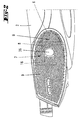
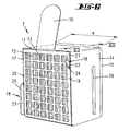
- the ultra-fine filter 7 has cassette-like plastic housing 11 with a rectangular outline.
- the two opposite flat sides are each with a grid-like Structure 12 provided what the flow through the plastic housing 11th allows.
- the free-standing Height h about a tenth of the narrow side dimension a des Rectangular cross section of the plastic housing 11 corresponds.
- the sealing lip height h is about 7 mm, an approximately semicircular sealing lip cross section is selected.
- An upper narrow side of the plastic housing 11 is assigned to the latter integrally molded a grip tab 16.
- This grip tab 16 is in Transverse direction rigid in itself, but so flexible on the plastic housing 11 tied in one piece so that the grip tab 16 fits into the upper Allows the narrow side position to pivot.
- the connection of the Handle tab 16 takes place in the area of the sealing lip 15 opposite Outlet edge 17 by forming a film hinge.
- the short control cam 22 has a triangular shape viewed from the side Floor plan on, to form a downward facing and into the Longitudinal edge 19 tapering control bevels 24.
- the diametrically opposed long control cam 23 forms in Cover to the facing housing side surface one in the direction of Longitudinal edge 20 extending rail 25.
- this rail 25 opposite side of the case is another, laterally protruding and with Distance to the inlet edge 14 arranged rail 26 which, running parallel to the assigned longitudinal edge, at a distance from the upper, the tab 16 of the narrow side of the plastic housing 11 ends.
- the rail receptacles 27 are also offset, viewed in the blowing direction arranged to each other, according to the staggered arrangement of the Rails 25 and 26 of the fine filter 7.
- the rail receptacle 28 which can be assigned to the ultra-fine filter rail 26 is by a Breakthrough of an edge portion protruding into the receiving chamber 8 29 formed.
- This rail receptacle 28 is in the course of the insertion of the Fine filter 7 in the receiving chamber 8 in the area of the last fifth of Leave insertion path from the filter-side rail 26, so that the Fine filter 7 in this last fifth of the insertion path also across linear insertion direction predetermined by the rail receptacle 28 is movable.
- Rail receptacle 27 extends essentially over the entire Insertion depth along the inner wall of the receiving chamber and is partially in the Cross section U-shaped. Furthermore, this rail mount 27 so shaped that they are in an end section when viewed in the direction of insertion opens to the blow-out side B of the electric motor 6, for which one of the Discharge side B facing guide web 30 of the rail receptacle 27 in this end portion runs towards the outlet side B curved. This curved, open end portion of the guide web 30 is in the Representations with the reference number 31.
- the ultra-fine filter 7 When the fine filter 7 is inserted into the receiving chamber 8 the ultra-fine filter 7 first by means of its rails 25, 26 in the Rail receptacles 27, 28 guided in the direction of insertion. In the course of this the filter-side sealing lip 15 is first a straight insertion movement at a distance on a circumferential contact face 32 of a pale side Air duct passed (see Fig. 8). In the area of the last fifth of the The short control cam 22 arranged on the filter side enters the insertion path with its Control slopes 24 against one in the receiving chamber opening area arranged counter control surface 33, which is the superposition of the linear Insertion movement by advancing the fine filter 7 in the direction caused on the pale side B of the electric motor 6. This cross shift of the Fine filter 7 is through the opening of the rail receptacle 27 in the area of curved end portion 31 of the guide web 30 allows.
- the outlet side B By controlling the fine filter 7 towards the contact face 32 of the The outlet side B becomes the one on the plastic housing 11 of the fine filter 7 molded sealing lip 15 in a material-saving manner under elastic Deformation of the same pressed against the contact face 32.
- the sealing lip 15 lies in the finished position Insertion position of the fine filter 7 only in a lower area on the Facility end face 32 of the blow-out side B, due to the fact that the Fine filter 7 or the one corresponding to the contact face 32 Sealing surface of the sealing lip 15 extends inclined to the contact face 32.
- the desired sealing bias of the sealing lip 15 against the Facility end face 32 is only closed after the Receiving chamber 8 reached through the outlet grille 9.
- the latter points chamber-side control projections 34, which in the course of putting on the Blow out grille 9 by means of control bevels 35 by acting on the upper one Outlet narrow edge of the plastic housing 11 another control of the ultra-fine filter 7 in the direction of the blow-out side B.
- the control projections 34 In the reach behind the closed position of the receiving chamber 8 according to FIG. 11 the control projections 34 the fine filter 7 such that it is in contact with the Blown side B of the electric motor 6 is biased.
- the fine filter 7 is removed after the discharge grille 9 has been removed by pulling the handle tab 16 on the filter underside loading of the curved end portion 31 of the rail-side guide web 30 through the long control cam 23 of the ultra-fine filter 7, the same moving away from the system end face 32 Blow side B up to the rail-guided position for the straight pull-out of the Fine filter 7.
- the outlet grille 9 has a viewing opening 36, in which the visible side of the filter-side when the ultra-fine filter 7 is inserted Handle tab 16 is exposed (see FIG. 11). This outwards for the user visible side of the grip tab 16 can also provide information about wear the inserted ultra-fine filter 7.
- the viewing opening 36 also serves as a handle opening for removing the Blowout grille 9, here the flexible connection of the grip tab 16 to the Plastic housing 11 is advantageous, since it intervenes in the Handle / viewing opening 36 downward in the direction of the plastic housing 11 can dodge.
Landscapes
- Engineering & Computer Science (AREA)
- Mechanical Engineering (AREA)
- Filtering Of Dispersed Particles In Gases (AREA)
- Filters For Electric Vacuum Cleaners (AREA)
Applications Claiming Priority (2)
| Application Number | Priority Date | Filing Date | Title |
|---|---|---|---|
| DE20207256U | 2002-05-08 | ||
| DE20207256U DE20207256U1 (de) | 2002-05-08 | 2002-05-08 | Im Ausblasstrom eines Staubsaugers angeordneter Feinstfilter, sowie Staubsauger hierzu |
Publications (3)
| Publication Number | Publication Date |
|---|---|
| EP1360921A2 true EP1360921A2 (fr) | 2003-11-12 |
| EP1360921A3 EP1360921A3 (fr) | 2007-08-08 |
| EP1360921B1 EP1360921B1 (fr) | 2011-05-18 |
Family
ID=28459049
Family Applications (1)
| Application Number | Title | Priority Date | Filing Date |
|---|---|---|---|
| EP03008045A Expired - Lifetime EP1360921B1 (fr) | 2002-05-08 | 2003-04-14 | Filtre à mailles fines situé en sortie du flux d'air d'un aspirateur, et aspirateur correspondant |
Country Status (3)
| Country | Link |
|---|---|
| EP (1) | EP1360921B1 (fr) |
| AT (1) | ATE509562T1 (fr) |
| DE (1) | DE20207256U1 (fr) |
Families Citing this family (1)
| Publication number | Priority date | Publication date | Assignee | Title |
|---|---|---|---|---|
| DE102007040963A1 (de) | 2007-08-30 | 2009-03-05 | Miele & Cie. Kg | Staubsauger mit einem Motorgebläse, in dessen Ausblas-Luftstrom ein Feinfilter angeordnet ist |
Citations (3)
| Publication number | Priority date | Publication date | Assignee | Title |
|---|---|---|---|---|
| JPH01230329A (ja) | 1988-03-10 | 1989-09-13 | Tokyo Electric Co Ltd | 電気掃除機 |
| DE4322222A1 (de) | 1993-07-03 | 1995-01-12 | Licentia Gmbh | Filter für Staubsauger |
| JPH0947407A (ja) | 1995-08-08 | 1997-02-18 | Tec Corp | 電気掃除機 |
Family Cites Families (6)
| Publication number | Priority date | Publication date | Assignee | Title |
|---|---|---|---|---|
| DE8607553U1 (de) * | 1986-03-19 | 1986-05-15 | Vorwerk & Co Interholding Gmbh, 5600 Wuppertal | Abluftfilter für einen Staubsauger |
| JPH0811106B2 (ja) * | 1988-03-14 | 1996-02-07 | 株式会社テック | 電気掃除機 |
| DE9207802U1 (de) * | 1992-06-10 | 1993-10-14 | Siemens AG, 80333 München | Staubsauger |
| DE4325110A1 (de) * | 1993-07-27 | 1995-02-02 | Licentia Gmbh | Staubsauger mit einem Filter |
| US6085382A (en) * | 1997-01-10 | 2000-07-11 | White Consolidated Industries, Inc. | Air filtrating self-propelled upright vacuum cleaner |
| JPH11318784A (ja) * | 1998-05-11 | 1999-11-24 | Matsushita Electric Ind Co Ltd | 電気掃除機 |
-
2002
- 2002-05-08 DE DE20207256U patent/DE20207256U1/de not_active Expired - Lifetime
-
2003
- 2003-04-14 EP EP03008045A patent/EP1360921B1/fr not_active Expired - Lifetime
- 2003-04-14 AT AT03008045T patent/ATE509562T1/de active
Patent Citations (3)
| Publication number | Priority date | Publication date | Assignee | Title |
|---|---|---|---|---|
| JPH01230329A (ja) | 1988-03-10 | 1989-09-13 | Tokyo Electric Co Ltd | 電気掃除機 |
| DE4322222A1 (de) | 1993-07-03 | 1995-01-12 | Licentia Gmbh | Filter für Staubsauger |
| JPH0947407A (ja) | 1995-08-08 | 1997-02-18 | Tec Corp | 電気掃除機 |
Also Published As
| Publication number | Publication date |
|---|---|
| EP1360921A3 (fr) | 2007-08-08 |
| EP1360921B1 (fr) | 2011-05-18 |
| ATE509562T1 (de) | 2011-06-15 |
| DE20207256U1 (de) | 2003-09-18 |
Similar Documents
| Publication | Publication Date | Title |
|---|---|---|
| DE10142509B4 (de) | Staubsauger | |
| DE202009008286U1 (de) | Kochdunst-Eintrittsvorrichtung mit abnehmbarer deckelförmiger Verschließeinrichtung | |
| DE102013012083A1 (de) | Filterbeutel für einen Staubsauger | |
| DE202006016789U1 (de) | Anschlussstück für einen Staubfilterbeutel sowie mit einem solchen Anschlussstück ausgestatteter Staubfilterbeutel | |
| DE102007047118A1 (de) | Luftfilter und Kältegerät mit einem Luftfilter | |
| EP3677159A1 (fr) | Agencement d'un sac filtrant à poussière dans un aspirateur | |
| EP1348370A1 (fr) | Buse d'aspiration pour aspirateur | |
| DE10163525A1 (de) | Filtersperre für einen Staubsauger | |
| EP1933685B1 (fr) | Disposition d'un sac filtrant dans un aspirateur electrique, et aspirateur electrique equipe d'une tubulure | |
| EP0681444A1 (fr) | Appareil pour l'entretien de sols, notamment aspirateur, pourvu de poils de brosserie disposes de preference sur le bord exterieur et diriges vers le bas | |
| EP0818159A1 (fr) | Dispositif de nettoyage d'ongles sales | |
| DE202006010888U1 (de) | Luftdurchtrittsvorrichtung | |
| EP1360921A2 (fr) | Filtre à mailles fines situé en sortie du flux d'air d'un aspirateur, et aspirateur correspondant | |
| DE102004058391A1 (de) | Dunstabzugshaube | |
| EP1784108B1 (fr) | Dispositif de verrouillage de filtre sur lequel est forme un ressort | |
| DE102007037021A1 (de) | Filterbeutel mit einer Halteplatte | |
| DE202006016304U1 (de) | Filterbeutel | |
| DE102013019224A1 (de) | Schmutzsauger mit Schwenkklappe | |
| DE102020130485B4 (de) | Umluftvorrichtung für ein Kochfeld und Funktionseinheit aus einem Kochfeld, einem Möbel und einer Umluftvorrichtung | |
| EP2534991B1 (fr) | Buse de sol pour un aspirateur et aspirateur doté d'une telle buse de sol | |
| DE102019128050B4 (de) | Saugreinigungsgerät mit einem eine Sperreinrichtung aufweisenden Kammerdeckel | |
| DE102019102357B4 (de) | Vorrichtung zur Absperrung oder Steuerung des Durchflusses von schmutzbeladener Luft, Reinigungsgerät und Behältnis zum Abtrennen und/oder Sammeln von Schmutz mit einer solchen Vorrichtung | |
| DE102011080396A1 (de) | Filterträger für Geruchsfilterelement und Dunstabzugshaube | |
| DE202006017084U1 (de) | Anschlussstück für einen Staubfilterbeutel sowie mit einem solchen Anschlussstück ausgestatteter Staubfilterbeutel | |
| DE102011083505B4 (de) | Staubfangbehälter für Staubsauger |
Legal Events
| Date | Code | Title | Description |
|---|---|---|---|
| PUAI | Public reference made under article 153(3) epc to a published international application that has entered the european phase |
Free format text: ORIGINAL CODE: 0009012 |
|
| AK | Designated contracting states |
Kind code of ref document: A2 Designated state(s): AT BE BG CH CY CZ DE DK EE ES FI FR GB GR HU IE IT LI LU MC NL PT RO SE SI SK TR |
|
| AX | Request for extension of the european patent |
Extension state: AL LT LV MK |
|
| REG | Reference to a national code |
Ref country code: HK Ref legal event code: DE Ref document number: 1060038 Country of ref document: HK |
|
| PUAL | Search report despatched |
Free format text: ORIGINAL CODE: 0009013 |
|
| AK | Designated contracting states |
Kind code of ref document: A3 Designated state(s): AT BE BG CH CY CZ DE DK EE ES FI FR GB GR HU IE IT LI LU MC NL PT RO SE SI SK TR |
|
| AX | Request for extension of the european patent |
Extension state: AL LT LV MK |
|
| 17P | Request for examination filed |
Effective date: 20080206 |
|
| AKX | Designation fees paid |
Designated state(s): AT BE BG CH CY CZ DE DK EE ES FI FR GB GR HU IE IT LI LU MC NL PT RO SE SI SK TR |
|
| 17Q | First examination report despatched |
Effective date: 20080929 |
|
| REG | Reference to a national code |
Ref country code: HK Ref legal event code: WD Ref document number: 1060038 Country of ref document: HK |
|
| GRAP | Despatch of communication of intention to grant a patent |
Free format text: ORIGINAL CODE: EPIDOSNIGR1 |
|
| GRAS | Grant fee paid |
Free format text: ORIGINAL CODE: EPIDOSNIGR3 |
|
| GRAA | (expected) grant |
Free format text: ORIGINAL CODE: 0009210 |
|
| AK | Designated contracting states |
Kind code of ref document: B1 Designated state(s): AT BE BG CH CY CZ DE DK EE ES FI FR GB GR HU IE IT LI LU MC NL PT RO SE SI SK TR |
|
| REG | Reference to a national code |
Ref country code: GB Ref legal event code: FG4D Free format text: NOT ENGLISH |
|
| REG | Reference to a national code |
Ref country code: CH Ref legal event code: EP |
|
| REG | Reference to a national code |
Ref country code: IE Ref legal event code: FG4D Free format text: LANGUAGE OF EP DOCUMENT: GERMAN |
|
| REG | Reference to a national code |
Ref country code: DE Ref legal event code: R096 Ref document number: 50313691 Country of ref document: DE Effective date: 20110630 |
|
| REG | Reference to a national code |
Ref country code: NL Ref legal event code: VDEP Effective date: 20110518 |
|
| PG25 | Lapsed in a contracting state [announced via postgrant information from national office to epo] |
Ref country code: PT Free format text: LAPSE BECAUSE OF FAILURE TO SUBMIT A TRANSLATION OF THE DESCRIPTION OR TO PAY THE FEE WITHIN THE PRESCRIBED TIME-LIMIT Effective date: 20110919 Ref country code: SE Free format text: LAPSE BECAUSE OF FAILURE TO SUBMIT A TRANSLATION OF THE DESCRIPTION OR TO PAY THE FEE WITHIN THE PRESCRIBED TIME-LIMIT Effective date: 20110518 |
|
| PG25 | Lapsed in a contracting state [announced via postgrant information from national office to epo] |
Ref country code: CY Free format text: LAPSE BECAUSE OF FAILURE TO SUBMIT A TRANSLATION OF THE DESCRIPTION OR TO PAY THE FEE WITHIN THE PRESCRIBED TIME-LIMIT Effective date: 20110518 Ref country code: FI Free format text: LAPSE BECAUSE OF FAILURE TO SUBMIT A TRANSLATION OF THE DESCRIPTION OR TO PAY THE FEE WITHIN THE PRESCRIBED TIME-LIMIT Effective date: 20110518 Ref country code: SI Free format text: LAPSE BECAUSE OF FAILURE TO SUBMIT A TRANSLATION OF THE DESCRIPTION OR TO PAY THE FEE WITHIN THE PRESCRIBED TIME-LIMIT Effective date: 20110518 Ref country code: ES Free format text: LAPSE BECAUSE OF FAILURE TO SUBMIT A TRANSLATION OF THE DESCRIPTION OR TO PAY THE FEE WITHIN THE PRESCRIBED TIME-LIMIT Effective date: 20110829 Ref country code: GR Free format text: LAPSE BECAUSE OF FAILURE TO SUBMIT A TRANSLATION OF THE DESCRIPTION OR TO PAY THE FEE WITHIN THE PRESCRIBED TIME-LIMIT Effective date: 20110819 |
|
| REG | Reference to a national code |
Ref country code: IE Ref legal event code: FD4D |
|
| PG25 | Lapsed in a contracting state [announced via postgrant information from national office to epo] |
Ref country code: NL Free format text: LAPSE BECAUSE OF FAILURE TO SUBMIT A TRANSLATION OF THE DESCRIPTION OR TO PAY THE FEE WITHIN THE PRESCRIBED TIME-LIMIT Effective date: 20110518 |
|
| PG25 | Lapsed in a contracting state [announced via postgrant information from national office to epo] |
Ref country code: CZ Free format text: LAPSE BECAUSE OF FAILURE TO SUBMIT A TRANSLATION OF THE DESCRIPTION OR TO PAY THE FEE WITHIN THE PRESCRIBED TIME-LIMIT Effective date: 20110518 Ref country code: EE Free format text: LAPSE BECAUSE OF FAILURE TO SUBMIT A TRANSLATION OF THE DESCRIPTION OR TO PAY THE FEE WITHIN THE PRESCRIBED TIME-LIMIT Effective date: 20110518 Ref country code: IE Free format text: LAPSE BECAUSE OF FAILURE TO SUBMIT A TRANSLATION OF THE DESCRIPTION OR TO PAY THE FEE WITHIN THE PRESCRIBED TIME-LIMIT Effective date: 20110518 |
|
| PG25 | Lapsed in a contracting state [announced via postgrant information from national office to epo] |
Ref country code: SK Free format text: LAPSE BECAUSE OF FAILURE TO SUBMIT A TRANSLATION OF THE DESCRIPTION OR TO PAY THE FEE WITHIN THE PRESCRIBED TIME-LIMIT Effective date: 20110518 Ref country code: RO Free format text: LAPSE BECAUSE OF FAILURE TO SUBMIT A TRANSLATION OF THE DESCRIPTION OR TO PAY THE FEE WITHIN THE PRESCRIBED TIME-LIMIT Effective date: 20110518 Ref country code: DK Free format text: LAPSE BECAUSE OF FAILURE TO SUBMIT A TRANSLATION OF THE DESCRIPTION OR TO PAY THE FEE WITHIN THE PRESCRIBED TIME-LIMIT Effective date: 20110518 |
|
| PLBE | No opposition filed within time limit |
Free format text: ORIGINAL CODE: 0009261 |
|
| STAA | Information on the status of an ep patent application or granted ep patent |
Free format text: STATUS: NO OPPOSITION FILED WITHIN TIME LIMIT |
|
| 26N | No opposition filed |
Effective date: 20120221 |
|
| REG | Reference to a national code |
Ref country code: DE Ref legal event code: R097 Ref document number: 50313691 Country of ref document: DE Effective date: 20120221 |
|
| BERE | Be: lapsed |
Owner name: VORWERK & CO. INTERHOLDING G.M.B.H. Effective date: 20120430 |
|
| PG25 | Lapsed in a contracting state [announced via postgrant information from national office to epo] |
Ref country code: MC Free format text: LAPSE BECAUSE OF NON-PAYMENT OF DUE FEES Effective date: 20120430 |
|
| REG | Reference to a national code |
Ref country code: CH Ref legal event code: PL |
|
| GBPC | Gb: european patent ceased through non-payment of renewal fee |
Effective date: 20120414 |
|
| REG | Reference to a national code |
Ref country code: FR Ref legal event code: ST Effective date: 20121228 |
|
| PG25 | Lapsed in a contracting state [announced via postgrant information from national office to epo] |
Ref country code: LI Free format text: LAPSE BECAUSE OF NON-PAYMENT OF DUE FEES Effective date: 20120430 Ref country code: CH Free format text: LAPSE BECAUSE OF NON-PAYMENT OF DUE FEES Effective date: 20120430 Ref country code: GB Free format text: LAPSE BECAUSE OF NON-PAYMENT OF DUE FEES Effective date: 20120414 Ref country code: BE Free format text: LAPSE BECAUSE OF NON-PAYMENT OF DUE FEES Effective date: 20120430 |
|
| PG25 | Lapsed in a contracting state [announced via postgrant information from national office to epo] |
Ref country code: FR Free format text: LAPSE BECAUSE OF NON-PAYMENT OF DUE FEES Effective date: 20120430 |
|
| REG | Reference to a national code |
Ref country code: AT Ref legal event code: MM01 Ref document number: 509562 Country of ref document: AT Kind code of ref document: T Effective date: 20120414 |
|
| PG25 | Lapsed in a contracting state [announced via postgrant information from national office to epo] |
Ref country code: BG Free format text: LAPSE BECAUSE OF FAILURE TO SUBMIT A TRANSLATION OF THE DESCRIPTION OR TO PAY THE FEE WITHIN THE PRESCRIBED TIME-LIMIT Effective date: 20110818 |
|
| PG25 | Lapsed in a contracting state [announced via postgrant information from national office to epo] |
Ref country code: AT Free format text: LAPSE BECAUSE OF NON-PAYMENT OF DUE FEES Effective date: 20120414 |
|
| PG25 | Lapsed in a contracting state [announced via postgrant information from national office to epo] |
Ref country code: TR Free format text: LAPSE BECAUSE OF FAILURE TO SUBMIT A TRANSLATION OF THE DESCRIPTION OR TO PAY THE FEE WITHIN THE PRESCRIBED TIME-LIMIT Effective date: 20110518 |
|
| PG25 | Lapsed in a contracting state [announced via postgrant information from national office to epo] |
Ref country code: LU Free format text: LAPSE BECAUSE OF NON-PAYMENT OF DUE FEES Effective date: 20120414 |
|
| PG25 | Lapsed in a contracting state [announced via postgrant information from national office to epo] |
Ref country code: HU Free format text: LAPSE BECAUSE OF FAILURE TO SUBMIT A TRANSLATION OF THE DESCRIPTION OR TO PAY THE FEE WITHIN THE PRESCRIBED TIME-LIMIT Effective date: 20030414 |
|
| PGFP | Annual fee paid to national office [announced via postgrant information from national office to epo] |
Ref country code: IT Payment date: 20220429 Year of fee payment: 20 Ref country code: DE Payment date: 20220419 Year of fee payment: 20 |
|
| REG | Reference to a national code |
Ref country code: DE Ref legal event code: R071 Ref document number: 50313691 Country of ref document: DE |