EP1366253B1 - Appareil de travail mobile comprenant un systeme de surveillance de stabilite statique - Google Patents
Appareil de travail mobile comprenant un systeme de surveillance de stabilite statique Download PDFInfo
- Publication number
- EP1366253B1 EP1366253B1 EP02735106A EP02735106A EP1366253B1 EP 1366253 B1 EP1366253 B1 EP 1366253B1 EP 02735106 A EP02735106 A EP 02735106A EP 02735106 A EP02735106 A EP 02735106A EP 1366253 B1 EP1366253 B1 EP 1366253B1
- Authority
- EP
- European Patent Office
- Prior art keywords
- supporting
- foot
- tool according
- measuring
- stability
- Prior art date
- Legal status (The legal status is an assumption and is not a legal conclusion. Google has not performed a legal analysis and makes no representation as to the accuracy of the status listed.)
- Expired - Lifetime
Links
- 238000012544 monitoring process Methods 0.000 title abstract description 12
- 230000001419 dependent effect Effects 0.000 claims abstract description 9
- 238000012806 monitoring device Methods 0.000 claims abstract description 7
- 230000003247 decreasing effect Effects 0.000 claims description 2
- 230000003287 optical effect Effects 0.000 claims description 2
- 230000005540 biological transmission Effects 0.000 claims 1
- 238000011156 evaluation Methods 0.000 abstract description 12
- 238000005259 measurement Methods 0.000 abstract description 11
- 238000005070 sampling Methods 0.000 abstract description 3
- 238000010276 construction Methods 0.000 description 5
- 230000000694 effects Effects 0.000 description 3
- 230000005484 gravity Effects 0.000 description 3
- 230000008033 biological extinction Effects 0.000 description 1
- 238000009530 blood pressure measurement Methods 0.000 description 1
- 238000010586 diagram Methods 0.000 description 1
- 238000000034 method Methods 0.000 description 1
- 238000012986 modification Methods 0.000 description 1
- 230000004048 modification Effects 0.000 description 1
- 238000012545 processing Methods 0.000 description 1
- 238000005086 pumping Methods 0.000 description 1
- 230000008054 signal transmission Effects 0.000 description 1
- 239000002689 soil Substances 0.000 description 1
- 230000003068 static effect Effects 0.000 description 1
- 239000000725 suspension Substances 0.000 description 1
- 230000000007 visual effect Effects 0.000 description 1
Images


Classifications
-
- G—PHYSICS
- G01—MEASURING; TESTING
- G01L—MEASURING FORCE, STRESS, TORQUE, WORK, MECHANICAL POWER, MECHANICAL EFFICIENCY, OR FLUID PRESSURE
- G01L5/00—Apparatus for, or methods of, measuring force, work, mechanical power, or torque, specially adapted for specific purposes
- G01L5/0061—Force sensors associated with industrial machines or actuators
- G01L5/0071—Specific indicating arrangements, e.g. of overload
-
- E—FIXED CONSTRUCTIONS
- E04—BUILDING
- E04G—SCAFFOLDING; FORMS; SHUTTERING; BUILDING IMPLEMENTS OR AIDS, OR THEIR USE; HANDLING BUILDING MATERIALS ON THE SITE; REPAIRING, BREAKING-UP OR OTHER WORK ON EXISTING BUILDINGS
- E04G21/00—Preparing, conveying, or working-up building materials or building elements in situ; Other devices or measures for constructional work
- E04G21/02—Conveying or working-up concrete or similar masses able to be heaped or cast
- E04G21/04—Devices for both conveying and distributing
-
- B—PERFORMING OPERATIONS; TRANSPORTING
- B66—HOISTING; LIFTING; HAULING
- B66C—CRANES; LOAD-ENGAGING ELEMENTS OR DEVICES FOR CRANES, CAPSTANS, WINCHES, OR TACKLES
- B66C23/00—Cranes comprising essentially a beam, boom, or triangular structure acting as a cantilever and mounted for translatory of swinging movements in vertical or horizontal planes or a combination of such movements, e.g. jib-cranes, derricks, tower cranes
- B66C23/62—Constructional features or details
- B66C23/72—Counterweights or supports for balancing lifting couples
- B66C23/78—Supports, e.g. outriggers, for mobile cranes
-
- B—PERFORMING OPERATIONS; TRANSPORTING
- B66—HOISTING; LIFTING; HAULING
- B66C—CRANES; LOAD-ENGAGING ELEMENTS OR DEVICES FOR CRANES, CAPSTANS, WINCHES, OR TACKLES
- B66C23/00—Cranes comprising essentially a beam, boom, or triangular structure acting as a cantilever and mounted for translatory of swinging movements in vertical or horizontal planes or a combination of such movements, e.g. jib-cranes, derricks, tower cranes
- B66C23/62—Constructional features or details
- B66C23/72—Counterweights or supports for balancing lifting couples
- B66C23/78—Supports, e.g. outriggers, for mobile cranes
- B66C23/80—Supports, e.g. outriggers, for mobile cranes hydraulically actuated
-
- B—PERFORMING OPERATIONS; TRANSPORTING
- B66—HOISTING; LIFTING; HAULING
- B66C—CRANES; LOAD-ENGAGING ELEMENTS OR DEVICES FOR CRANES, CAPSTANS, WINCHES, OR TACKLES
- B66C23/00—Cranes comprising essentially a beam, boom, or triangular structure acting as a cantilever and mounted for translatory of swinging movements in vertical or horizontal planes or a combination of such movements, e.g. jib-cranes, derricks, tower cranes
- B66C23/88—Safety gear
- B66C23/90—Devices for indicating or limiting lifting moment
-
- B—PERFORMING OPERATIONS; TRANSPORTING
- B66—HOISTING; LIFTING; HAULING
- B66C—CRANES; LOAD-ENGAGING ELEMENTS OR DEVICES FOR CRANES, CAPSTANS, WINCHES, OR TACKLES
- B66C23/00—Cranes comprising essentially a beam, boom, or triangular structure acting as a cantilever and mounted for translatory of swinging movements in vertical or horizontal planes or a combination of such movements, e.g. jib-cranes, derricks, tower cranes
- B66C23/88—Safety gear
- B66C23/90—Devices for indicating or limiting lifting moment
- B66C23/905—Devices for indicating or limiting lifting moment electrical
-
- E—FIXED CONSTRUCTIONS
- E02—HYDRAULIC ENGINEERING; FOUNDATIONS; SOIL SHIFTING
- E02F—DREDGING; SOIL-SHIFTING
- E02F9/00—Component parts of dredgers or soil-shifting machines, not restricted to one of the kinds covered by groups E02F3/00 - E02F7/00
- E02F9/08—Superstructures; Supports for superstructures
- E02F9/085—Ground-engaging fitting for supporting the machines while working, e.g. outriggers, legs
-
- E—FIXED CONSTRUCTIONS
- E04—BUILDING
- E04G—SCAFFOLDING; FORMS; SHUTTERING; BUILDING IMPLEMENTS OR AIDS, OR THEIR USE; HANDLING BUILDING MATERIALS ON THE SITE; REPAIRING, BREAKING-UP OR OTHER WORK ON EXISTING BUILDINGS
- E04G21/00—Preparing, conveying, or working-up building materials or building elements in situ; Other devices or measures for constructional work
- E04G21/02—Conveying or working-up concrete or similar masses able to be heaped or cast
- E04G21/04—Devices for both conveying and distributing
- E04G21/0418—Devices for both conveying and distributing with distribution hose
- E04G21/0436—Devices for both conveying and distributing with distribution hose on a mobile support, e.g. truck
Definitions
- the invention relates to a mobile working device, in particular a truck-mounted concrete pump, with a chassis, with two front and two rear, extendable from a driving position in at least one support position and each with a preferably telescopic support leg supported on a support support arms, with a from a driving position in about the chassis cantilevered working positions extendable to a chassis-fixed vertical axis rotatable, preferably designed as a concrete distributor boom working boom, arranged in the region of the support feet measuring devices for determining the respective support load and acted upon by the output signals of the measuring devices for monitoring the stability, wherein in each support leg at least a force sensor is arranged, wherein each force sensor is arranged in an electrical measuring circuit for delivering a support load-dependent measuring signal and wherein the monitoring unit evaluation comprises an evaluation, which can be acted upon in given scanning cycles with Stützfuß concernede support load measurement values and their comparison with at least one predetermined stability-determining threshold.
- a working device is described in JP59 106 351.
- Mobile implements of this type are provided with extendable support arms, which are intended to improve the stability of the implement at the place of use.
- the support arms on the one hand have the task to eliminate the vehicle suspension and relieve the wheels.
- the support arms should reduce the danger of tipping, which results when high tilting moments occur over the work boom.
- the support legs of the outriggers form the corners of a quadrilateral, the sidelines of which describe an area within which the overall center of gravity of the implement must be, in order to ensure stability. Since the projecting work boom is rotatable, describes the overall focus in a Turn a full circle, which must lie in the working area of the work jib within the quadrilateral area.
- the present invention seeks to improve the stability of mobile equipment monitoring in terms of their accuracy and usability in complicated support situations.
- the solution according to the invention is based primarily on the idea that the evaluation electronics comprises a software routine for determining the second lowest support foot-related support load measurement value of each work cycle and for comparing it with a stability-determining threshold value. In doing so, it is taken into account that, taking into account the static indeterminacy of the four-point support, a three-point support will be established regularly during a movement the work jib to be changed Abstweilkonfigurationen leads. One of the support legs can even stand out from the ground, without endangering the tipping stability. Decisive for the stability according to the invention is always the second lowest stützfuß concernede support load reading. If this falls below a minimum force with decreasing tendency, an emergency shutdown of the boom movement and the pumping operation is indicated.
- the relevant reference value generator is set, for example, to a minimum force of 0.5 to 5% of the supporting leg-related maximum force.
- the invention also makes it possible to give an advance warning before reaching the said danger zone.
- another setpoint generator is provided for specifying a Vorwamkraft, for example, is at 5 to 10% of the supporting leg-related maximum load and the pump driver, for example via an acoustic and / or visual signal indicates that increased attention is required.
- the electrical measuring circuits are set to an increased measuring accuracy in a measuring range which includes the threshold values. Since the stability-determining thresholds are more likely to be found at the lower end of the support load scale, it is advantageous for the electrical measurement circuits to have an increasing measurement accuracy from high to low support foot-related support loads. It has proven to be particularly advantageous if the electrical measuring circuits are set to an increased measuring accuracy in a measuring range of less than 30%, preferably less than 15%, of the maximum load-bearing-related maximum load.
- This threshold value is expediently chosen such that, given a supporting surface, a fundamental fracture does not yet occur.
- a further preferred embodiment of the invention provides that the force sensor is arranged in a preferably subsequently attachable to the support foot element.
- the measuring circuit and, if appropriate, part of the evaluation electronics can also be integrated in the base element.
- the measuring circuit is preferably coupled via a galvanic or wireless signal transmission path to the transmitter.
- a further preferred embodiment of the invention provides that in each support leg two preferably similar force sensors are arranged, which are arranged in independent measuring circuits for delivering a support load-dependent measurement signal.
- the evaluation electronics advantageously contain a software routine for the pairwise comparison of the measured values derived from the support foot-related measurement signals with regard to their agreement or non-conformity. Only if the measured values belonging to the individual support feet are equal in pairs within a predefined tolerance range can further processing within the evaluation electronics be possible. The resulting redundancy of the measuring system is necessary to ensure reliable monitoring of the device support.
- the force sensors expediently have a strain gauge or a piezoelectric element.
- the electrical measuring circuits advantageously contain a bridge circuit, in which a branch of the associated force sensor is arranged and whose output is connected to an operational amplifier.
- the arrangement according to the invention allows real-time monitoring of the vertical load in the area of the individual support feet in a tight time frame, so that dynamic effects and inertial effects during operation of the working device can also be included in the monitoring.
- the mobile concrete pump shown in Fig. 1 consists essentially of a multi-axle chassis 10, a rotatably mounted on a near-axis mast block 12 about a chassis-fixed vertical axis 13 concrete distribution boom 14 and a support structure 15 which has a chassis-fixed support frame 16, two on the support frame 16 in each case designed as a Ausschubkasten telescopic segment 18 displaceable front support arm 20 and two pivotable about a vertical axis 22 rear support arm 24.
- the support arms 20,24 are each supported with a downwardly extendable support leg 26 on the ground 28.
- the front and rear support arms 20,24 are extendable by hydraulic means from a driving position close to the chassis in a support position.
- a narrow support was selected on the road side.
- the narrow support with the space problems on construction sites can be taken into account, inevitably leads to a restriction in the rotation angle of the work boom 14th
- the quadrilateral sides must not be externally extended when moving the jib from the overall center of gravity of the system.
- the invention makes use of the knowledge that the position of the center of gravity within the tilting quadrilateral can be monitored by supporting load sensors on the supporting feet 26 forming the corners of the tilting quadrilateral.
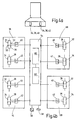
- a sensor unit 30 which comprises two force sensors 32,34 with associated electrical measuring circuit 36,38 and operational amplifier 40,42.
- Each measuring circuit 36, 38 transmits, via its amplifier 40, 42, a load-cell-dependent measuring signal which can be scanned in given time cycles and which is processed in a central evaluation electronics 54.
- the evaluation electronics 54 contains a software routine 60 for pairwise comparison of the measured values derived from the support foot-related measurement signals with respect to their match. If this match does not exist for several sampling cycles, this indicates a measuring or electronic fault, which leads to an emergency shutdown of the system and thus to a decommissioning of the truck-mounted concrete pump.
- the transmitter 54 includes a software routine 62 for determining the second lowest stem-foot-support-load value of each sampling cycle and comparing it to a stability-determining threshold.
- a support structure 15 with four support legs 26 is statically overdetermined, so that in each constellation of the work jib 14 only three of the four stützfuß dream measured values for stability are important.
- the stability is basically given when three support legs 26 still attacks a vertical load that exceeds a predetermined minimum force. After extension of the support arms 20, 24, the measured vertical load is normally greater than a predetermined prewarning force in all support legs 26. If the work boom 14 is moved, a support leg 26 can even lift completely without risk of stability from the ground.
- a warning (acoustic / optical) is issued only when the vertical load on another support leg 26 drops below the Vorwarnkraft. If the respective support leg still further relieved and its support load falls below the predetermined minimum force, the movement of the work boom 14 and the operation of the concrete pump by interrupting the pressure oil supply via an emergency stop valve 56 is turned off. In this state, the operator by an emergency operation, accompanied by an audible horn signal, the work boom 14 under its own responsibility from the danger zone recover.
- a beacon 58 may also indicate to the operator the status of the alert. When manually operated Bergevorgangs this shows Rundumgna 58 by extinction that the vertical load in three support legs 26 has exceeded the minimum force again.
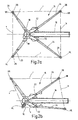
- the sensor unit 30 is clamped between a pendulum foot 44 of the support leg 26 and a foot plate 46 which can be set up directly on the floor.
- the foot plate 46 with sensor unit 30 is subsequently attached to an existing pendulum foot 44 of the support leg 26, while in the case of Fig. 3b the pendulum foot 44 is provided with a comprehensive construction that replaces the original pendulum foot.
- the construction according to FIG. 3b accordingly builds lower than the construction according to FIG. 3a and is also protected by a cover 48 against dirt ingress and damage from the outside.
- the measuring circuits 36,38 are formed as Wheatstone bridges, on one branch of which is designed as DehnmeßstMail force sensor 32 and 34 is arranged.
- the diagonal taps 50,52 of the measuring circuits 36,38 are applied to the inputs of the associated operational amplifier 40,42, at the output of the support load-proportional electrical measurement signal can be tapped.
- the measuring range of 4 to 20 mA at the output of the amplifier 40,42 is used to obtain the highest possible accuracy at low force values. Accordingly, the measurement accuracy is increased by appropriate adjustment of the amplifier in a range corresponding to about 20% of the maximum load occurring at a support foot. For larger support loads, the maximum value (eg: 20 mA) is always tapped at the amplifier output.
- the invention relates to a mobile implement, in particular a truck-mounted concrete pump with a device for monitoring the stability during operation.
- the implement includes a chassis 10 that includes a support structure having two front and two rearward support brackets 20.
- the support arms are extendable from a driving position in at least one support position and each supported with a telescopic support leg 26 on a support 28.
- the implement further comprises a projecting from a driving position in about the chassis projecting work positions, about a chassis-fixed vertical axis rotatable, preferably designed as a concrete distributor boom working boom 14.
- In the area of the support feet measuring devices for determining the respective vertical load are arranged, whose output signals are fed to a device for monitoring the stability.
- At least one force sensor 32, 34 is arranged in each support leg, which in turn is arranged in an electrical measuring circuit 36, 38 for delivering a support load-dependent measuring signal.
- the monitoring device comprises evaluation electronics 54 which can be acted upon in predetermined scanning cycles with the supporting foot-related supporting load measured values and their comparison with at least one predetermined stability-determining threshold value.
Landscapes
- Engineering & Computer Science (AREA)
- Mechanical Engineering (AREA)
- Architecture (AREA)
- Civil Engineering (AREA)
- Structural Engineering (AREA)
- Analytical Chemistry (AREA)
- General Engineering & Computer Science (AREA)
- Chemical & Material Sciences (AREA)
- Mining & Mineral Resources (AREA)
- Physics & Mathematics (AREA)
- General Physics & Mathematics (AREA)
- On-Site Construction Work That Accompanies The Preparation And Application Of Concrete (AREA)
- Jib Cranes (AREA)
- Forklifts And Lifting Vehicles (AREA)
- Arrangements For Transmission Of Measured Signals (AREA)
- Investigating Or Analysing Materials By The Use Of Chemical Reactions (AREA)
- Telephone Function (AREA)
- Vehicle Cleaning, Maintenance, Repair, Refitting, And Outriggers (AREA)
Claims (21)
- Appareil de travail mobile, en particulier pompe à béton automotrice, avec un châssis (10), avec deux béquilles (20) avant et deux arrière, déployables d'une position de roulement ou de route dans au moins une position d'appui et pouvant s'appuyer chacune sur un support (28) par un pied d'appui (26) télescopique, avec un bras de travail (14) déployable d'une position de route dans des positions de travail en saillie ou en porte-à-faux par rapport au châssis, pivotant autour d'un axe vertical (13) lié au châssis, réalisé de préférence sous forme de mât de distribution de béton, avec des dispositifs de mesure (30) disposés au niveau des pieds d'appui (26) pour déterminer la charge d'appui respective et avec un dispositif pouvant être soumis aux signaux de sortie des dispositifs de mesure pour surveiller la stabilité, au moins un capteur de force (32, 34) étant disposé dans chaque pied d'appui (26), chaque capteur de force étant disposé dans un circuit électrique de mesure (36, 38) conçu pour délivrer un signal de mesure dépendant de la charge d'appui et le dispositif de surveillance comprenant une électronique d'évaluation (54) qui peut être soumise, à des cycles d'échantillonnage prédéfinis, aux valeurs de mesure de charge d'appui relatives aux béquilles et, pour leur comparaison, à au moins une valeur seuil prédéfinie déterminante pour la stabilité, caractérisé par le fait que les circuits électriques de mesure (36, 38) présentent une précision de mesure décroissante des basses vers les hautes valeurs de mesure de charge d'appui relatives aux béquilles.
- Appareil de travail selon la revendication 1, caractérisé par le fait que les circuits électriques de mesure (36, 38) sont réglés sur une précision de mesure plus élevée dans une plage de mesure au-dessous de 30 %, de préférence au-dessous de 15 % de la charge maximale par béquille.
- Appareil de travail selon la revendication 1 ou 2, caractérisé par le fait que la précision de mesure des circuits électriques de mesure (36, 38) est commutable au choix.
- Appareil de travail selon l'une des revendications 1 à 3, caractérisé par le fait que deux capteurs de force (32, 34) de préférence de même nature sont disposés dans chaque pied d'appui (26) et situés dans des circuits de mesure (36, 38) indépendants conçus pour délivrer un signal de mesure dépendant de la charge d'appui.
- Appareil de travail selon la revendication 4, caractérisé par le fait que l'électronique d'évaluation (54) contient une routine logicielle (60) pour la comparaison par paires des valeurs de mesure déduites des signaux de mesure relatifs aux béquilles en ce qui concerne leur coïncidence.
- Appareil de travail selon l'une des revendications 1 à 5, caractérisé par le fait que l'électronique d'évaluation (54) comprend une routine logicielle (62) pour déterminer la deuxième plus faible valeur de mesure de charge d'appui relative aux béquilles de chaque cycle d'échantillonnage et la comparer avec une valeur seuil déterminante pour la stabilité.
- Appareil de travail mobile, en particulier pompe à béton automotrice, avec un châssis (10), avec deux béquilles (20) avant et deux arrière, déployables d'une position de roulement ou de route dans au moins une position d'appui et pouvant s'appuyer chacune sur un support (28) par un pied d'appui (26) télescopique, avec un bras de travail (14) déployable d'une position de route dans des positions de travail en porte-à-faux par rapport au châssis, pivotant autour d'un axe vertical (13) lié au châssis, réalisé de préférence sous forme de mât de distribution de béton, avec des dispositifs de mesure (30) disposés au niveau des pieds d'appui (26) pour déterminer la charge d'appui respective et avec un dispositif pouvant être soumis aux signaux de sortie des dispositifs de mesure pour surveiller la stabilité, au moins un capteur de force (32, 34) étant disposé dans chaque pied d'appui (26), chaque capteur de force étant disposé dans un circuit électrique de mesure (36, 38) conçu pour délivrer un signal de mesure dépendant de la charge d'appui et le dispositif de surveillance comprenant une électronique d'évaluation (54) qui peut être soumise, à des cycles d'échantillonnage prédéfinis, aux valeurs de mesure de charge d'appui relatives aux béquilles et, pour leur comparaison, à au moins une valeur seuil prédéfinie déterminante pour la stabilité, caractérisé par le fait que l'électronique d'évaluation (54) comprend une routine logicielle (62) pour déterminer la deuxième plus faible valeur de mesure de charge d'appui relative aux béquilles de chaque cycle d'échantillonnage et la comparer avec une valeur seuil déterminante pour la stabilité.
- Appareil de travail selon l'une des revendications 1 à 7, caractérisé par le fait que l'électronique d'évaluation (54) comprend une routine logicielle pour déterminer la valeur de mesure de charge d'appui relative aux béquilles la plus élevée de chaque cycle d'échantillonnage et la comparer avec une valeur seuil déterminante pour la stabilité.
- Appareil de travail selon l'une des revendications 1 à 8, caractérisé par le fait que l'électronique d'évaluation (54) présente un transmetteur de valeur seuil pour fixer une force minimale.
- Appareil de travail selon l'une des revendications 1 à 9, caractérisé par le fait que l'électronique d'évaluation (54) présente un transmetteur de valeur seuil pour fixer une force d'avertissement.
- Appareil de travail selon l'une des revendications 1 à 10, caractérisé par le fait que l'électronique d'évaluation (54) présente un transmetteur de valeur seuil pour fixer une force maximale.
- Appareil de travail selon l'une des revendications 1 à 11, caractérisé par le fait que l'électronique d'évaluation (54) est reliée à un dispositif de commande (56) pour la commande du bras de travail (14).
- Appareil de travail selon l'une des revendications 1 à 12, caractérisé par le fait que l'électronique d'évaluation (54) est reliée à un dispositif de commande (56) pour la commande d'une pompe à béton.
- Appareil de travail selon l'une des revendications 1 à 13, caractérisé par le fait que l'électronique d'évaluation (54) est reliée à un transmetteur de signaux acoustiques et/ou optiques (58).
- Appareil de travail selon l'une des revendications 1 à 14, caractérisé par le fait que les capteurs de force (32, 34) présentent une jauge de contrainte.
- Appareil de travail selon l'une des revendications 1 à 15, caractérisé par le fait que les capteurs de force (32, 34) sont réalisés sous la forme de capteurs piézoélectriques.
- Appareil de travail selon l'une des revendications 1 à 16, caractérisé par le fait que les circuits électriques de mesure (36, 38) contiennent un circuit en pont dans une branche duquel le capteur de force (32, 34) associé est disposé.
- Appareil de travail selon la revendication 17, caractérisé par le fait que les circuits électriques de mesure (36, 38) contiennent un amplificateur opérationnel (40, 42) relié côté entrée aux sorties diagonales (50, 52) du circuit en pont.
- Appareil de travail selon l'une des revendications 1 à 18, caractérisé par le fait que les capteurs de force (32, 34) sont disposés dans un élément de pied (44, 46) pouvant de préférence être fixé après coup sur le pied d'appui (26).
- Appareil de travail selon la revendication 19, caractérisé par le fait que ledit au moins un circuit de mesure (36, 38) est intégré dans l'élément de pied associé.
- Appareil de travail selon la revendication 20, caractérisé par le fait que ledit au moins un circuit de mesure (36, 38) est couplé à l'électronique d'évaluation (54) par une ligne de transmission galvanique ou sans fil.
Priority Applications (1)
| Application Number | Priority Date | Filing Date | Title |
|---|---|---|---|
| EP05028455A EP1659235B1 (fr) | 2001-03-02 | 2002-02-27 | Moyen mobile de travail avec dispositif de surveillance de la stabilité |
Applications Claiming Priority (3)
| Application Number | Priority Date | Filing Date | Title |
|---|---|---|---|
| DE10110176 | 2001-03-02 | ||
| DE10110176A DE10110176A1 (de) | 2001-03-02 | 2001-03-02 | Mobiles Arbeitsgerät mit Standsicherheitsüberwachung |
| PCT/EP2002/002053 WO2002075076A2 (fr) | 2001-03-02 | 2002-02-27 | Appareil de travail mobile comprenant un systeme de surveillance de stabilite statique |
Related Child Applications (1)
| Application Number | Title | Priority Date | Filing Date |
|---|---|---|---|
| EP05028455A Division EP1659235B1 (fr) | 2001-03-02 | 2002-02-27 | Moyen mobile de travail avec dispositif de surveillance de la stabilité |
Publications (2)
| Publication Number | Publication Date |
|---|---|
| EP1366253A2 EP1366253A2 (fr) | 2003-12-03 |
| EP1366253B1 true EP1366253B1 (fr) | 2006-09-06 |
Family
ID=7676130
Family Applications (2)
| Application Number | Title | Priority Date | Filing Date |
|---|---|---|---|
| EP05028455A Expired - Lifetime EP1659235B1 (fr) | 2001-03-02 | 2002-02-27 | Moyen mobile de travail avec dispositif de surveillance de la stabilité |
| EP02735106A Expired - Lifetime EP1366253B1 (fr) | 2001-03-02 | 2002-02-27 | Appareil de travail mobile comprenant un systeme de surveillance de stabilite statique |
Family Applications Before (1)
| Application Number | Title | Priority Date | Filing Date |
|---|---|---|---|
| EP05028455A Expired - Lifetime EP1659235B1 (fr) | 2001-03-02 | 2002-02-27 | Moyen mobile de travail avec dispositif de surveillance de la stabilité |
Country Status (9)
| Country | Link |
|---|---|
| US (1) | US7012540B2 (fr) |
| EP (2) | EP1659235B1 (fr) |
| JP (1) | JP2004526082A (fr) |
| KR (1) | KR100838898B1 (fr) |
| CN (1) | CN1246557C (fr) |
| AT (2) | ATE416285T1 (fr) |
| DE (3) | DE10110176A1 (fr) |
| ES (2) | ES2271260T3 (fr) |
| WO (1) | WO2002075076A2 (fr) |
Cited By (3)
| Publication number | Priority date | Publication date | Assignee | Title |
|---|---|---|---|---|
| DE202009004673U1 (de) | 2008-08-29 | 2010-01-28 | Liebherr-Werk Ehingen Gmbh | Kolben-Zylinder-Einheit |
| EP3498548B1 (fr) | 2016-12-15 | 2020-09-30 | Alois Kober GmbH | Agencement de levage doté d'un dispositif de sécurité |
| WO2022200253A1 (fr) * | 2021-03-23 | 2022-09-29 | Putzmeister Engineering Gmbh | Fonction de surveillance de stabilité à sécurité intégrée pour un système de transport de matières épaisses |
Families Citing this family (46)
| Publication number | Priority date | Publication date | Assignee | Title |
|---|---|---|---|---|
| JP3683571B2 (ja) * | 2003-04-10 | 2005-08-17 | 古河機械金属株式会社 | クレーンの転倒防止装置 |
| DE10320382A1 (de) * | 2003-05-06 | 2004-12-23 | Universität Stuttgart vertreten durch das Institut für Geotechnik | Mobile Arbeitsmaschine mit Stützauslegern |
| DE10349234A1 (de) * | 2003-10-20 | 2005-05-19 | Putzmeister Ag | Mobiles Arbeitsgerät mit Stützauslegern |
| DE102004012966A1 (de) * | 2004-03-17 | 2005-10-06 | Putzmeister Ag | Mobiles Arbeitsgerät mit Stützauslegern sowie Verfahren zur Aufstellung eines solchen Geräts |
| DE202005005705U1 (de) * | 2005-04-08 | 2005-08-25 | B. Teupen Maschinenbau Gmbh | Transportable Arbeitsmaschine mit einem auf einem Drehtisch montierten Auslegerarm |
| DE202005013310U1 (de) * | 2005-08-23 | 2007-01-04 | Liebherr-Hydraulikbagger Gmbh | Überlastwarneinrichtung für Bagger |
| FR2898120B1 (fr) * | 2006-03-03 | 2008-05-02 | Manitou Bf Sa | "dispositif de commande, notamment pour machine de manutention" |
| ITMI20060818A1 (it) * | 2006-04-24 | 2007-10-25 | Cifa Spa | Sistema perfezionato per la sorveglianza e il controllo del funzionamento di macchinari semoventi a braccio articolato,quali pompe per calcestruzzo |
| DE102006031257A1 (de) * | 2006-07-06 | 2008-01-10 | Putzmeister Ag | Autobetonpumpe mit Knickmast |
| DE102006032094A1 (de) * | 2006-07-11 | 2008-01-17 | Siemens Ag | Röntgensystem mit einem Industrieroboter |
| DE202006017730U1 (de) * | 2006-11-21 | 2008-04-03 | Liebherr-Werk Ehingen Gmbh | Mobilkran |
| DE202006017724U1 (de) * | 2006-11-21 | 2008-04-03 | Liebherr-Werk Ehingen Gmbh | Mobilkran |
| DE102008021627A1 (de) * | 2008-04-30 | 2009-11-12 | Liebherr-Werk Ehingen Gmbh | Mobilkran und Verfahren zum Betreiben eines Mobilkranes |
| DE102008058937A1 (de) | 2008-05-21 | 2009-11-26 | Putzmeister Concrete Pumps Gmbh | Mobiles Arbeitsgerät mit Standsicherheitsüberwachung |
| DE102008058758A1 (de) | 2008-11-19 | 2010-05-20 | Brosa Ag | Kraftaufnehmer für mit einem Hydraulikzylinder betätigten Stützausleger |
| CN101833287B (zh) * | 2010-03-30 | 2012-02-22 | 三一重工股份有限公司 | 工程机械及其稳定性控制系统 |
| NL2006268C2 (en) * | 2011-02-21 | 2012-08-22 | Reedijk Hydrauliek B V | Mobile crane and method of operating a mobile crane. |
| DE102011075310A1 (de) * | 2011-05-05 | 2012-11-08 | Putzmeister Engineering Gmbh | Fahrbare Arbeitsmaschine mit Abstützvorrichtung |
| CN102322253B (zh) * | 2011-05-06 | 2015-08-12 | 三一重工股份有限公司 | 一种工程机械及其工况控制方法、装置 |
| CN102277891B (zh) * | 2011-05-19 | 2013-06-05 | 徐工集团工程机械股份有限公司科技分公司 | 步履式工程机械及其调平装置 |
| CN102303570B (zh) * | 2011-06-22 | 2012-11-28 | 中联重科股份有限公司 | 伸展和调平工程车辆的支腿的方法和系统 |
| PL2815135T3 (pl) * | 2012-02-13 | 2020-01-31 | Palfinger Ag | Urządzenie podpierające dla pojazdu |
| CN102768088B (zh) * | 2012-08-09 | 2015-03-11 | 三一重工股份有限公司 | 一种悬臂结构弯矩的获取方法、装置及工程机械 |
| AT13517U1 (de) | 2012-10-19 | 2014-02-15 | Palfinger Ag | Sicherheitseinrichtung für einen Kran |
| US9365398B2 (en) | 2012-10-31 | 2016-06-14 | Manitowoc Crane Companies, Llc | Outrigger pad monitoring system |
| CN102979310B (zh) * | 2012-12-24 | 2015-04-01 | 中联重科股份有限公司 | 工程设备及其动力控制方法 |
| DE102013000463A1 (de) | 2013-01-03 | 2014-07-03 | Terex Cranes Germany Gmbh | Mobiles Arbeitsgerät, insbesondere Mobilkran |
| DE102013220334A1 (de) * | 2013-10-09 | 2015-04-09 | Putzmeister Engineering Gmbh | Stützvorrichtung für ein mobiles Arbeitsgerät |
| CN104591050A (zh) * | 2014-11-28 | 2015-05-06 | 杭州爱知工程车辆有限公司 | 高空作业车防倾翻控制方法 |
| DE102015003177A1 (de) * | 2015-03-12 | 2016-09-15 | Liebherr-Werk Nenzing Gmbh | Verfahren zum Betrieb einer mobilen Arbeitsmaschine mit Bodendruckbegrenzung |
| CA2943939C (fr) * | 2015-09-30 | 2021-10-19 | Deere & Company | Systeme d'alerte de stabilite et d'intervention de controle destine a un vehicule forestier |
| JP2019516539A (ja) * | 2016-03-25 | 2019-06-20 | ストーンエイジ, インコーポレイテッドStoneage, Inc. | 高圧洗浄ランスドライブ安全装置 |
| US10543817B2 (en) | 2016-12-15 | 2020-01-28 | Schwing America, Inc. | Powered rear outrigger systems |
| NL2019784B1 (en) * | 2017-10-23 | 2019-04-29 | Spierings Group B V | Outrigger assembly and vehicle, such as a mobile crane, comprising the outrigger assembly |
| DK3489419T3 (da) | 2017-11-27 | 2020-07-27 | Cargotec Patenter Ab | Stabilisatorbenarrangement og mobil arbejdsmaskine omfattende et sådan stabilisatorbenarrangement |
| DE102018204079A1 (de) | 2018-03-16 | 2019-09-19 | Putzmeister Engineering Gmbh | Autobetonpumpe und Verfahren zur stabilitätsrelevanten Steuerung einer Autobetonpumpe |
| US10466719B2 (en) | 2018-03-28 | 2019-11-05 | Fhe Usa Llc | Articulated fluid delivery system with remote-controlled spatial positioning |
| DK3670425T3 (da) * | 2018-12-21 | 2021-08-23 | Hiab Ab | Stabilisatorbenanordning og fremgangsmåde til at registrere, om et stabilisatorben er eller ikke er i støttende kontakt med jorden |
| DE102019113881A1 (de) * | 2019-02-12 | 2020-08-13 | Putzmeister Engineering Gmbh | Betonpumpe und Verfahren zum Abstützen einer Betonpumpe |
| EP3925925B1 (fr) * | 2019-02-14 | 2024-10-16 | Tadano Ltd. | Dispositif de commande de stabilisateur |
| CN112116787B (zh) * | 2020-09-01 | 2022-04-12 | 水木鸟(重庆)安全技术有限公司 | 物联网气体探测报警控制系统 |
| CN112758011A (zh) * | 2020-12-29 | 2021-05-07 | 徐州徐工施维英机械有限公司 | 一种混凝土泵车防倾覆预警方法和装置 |
| WO2022240894A1 (fr) * | 2021-05-11 | 2022-11-17 | Celestial Oncology Inc. | Système de radiothérapie robotique couplé |
| DE102021125042B3 (de) * | 2021-09-28 | 2023-02-23 | Putzmeister Engineering Gmbh | Nachstützüberwachung für ein Dickstofffördersystem |
| DE102022116319A1 (de) * | 2022-06-30 | 2024-01-04 | Liebherr-Mischtechnik Gmbh | Verfahren zur Überwachung der Standsicherheit einer Arbeitsmaschine |
| SE547555C2 (en) * | 2023-04-24 | 2025-10-14 | Huddig Ab | An excavation aggregate for a utility vehicle, a utility vehicle and a method for balancing an excavation aggregate |
Family Cites Families (31)
| Publication number | Priority date | Publication date | Assignee | Title |
|---|---|---|---|---|
| US2980414A (en) * | 1956-03-16 | 1961-04-18 | Cherry Burrell Corp | Compression bracket |
| US3072209A (en) * | 1959-11-16 | 1963-01-08 | Cherry Burrell Corp | Mounting for force measuring device |
| US3277718A (en) * | 1961-08-01 | 1966-10-11 | Baldwin Lima Hamilton Corp | Electrical pressure transducer |
| DE1531166A1 (de) * | 1967-10-04 | 1969-12-18 | Calor Emag Elek Zitaets Ag | Einrichtung zur UEberwachung der Kippsicherheit von Kraenen,insbesondere bei Mobilkraenen |
| US3713129A (en) * | 1970-03-30 | 1973-01-23 | R Buchholz | Crane overloading protective system |
| US3680714A (en) * | 1970-07-22 | 1972-08-01 | Case Co J I | Safety device for mobile cranes |
| US3712294A (en) * | 1970-07-24 | 1973-01-23 | J Muller | Method and apparatus for measuring human reaction |
| DE2230546C3 (de) | 1972-06-22 | 1982-01-21 | Magirus-Deutz Ag, 7900 Ulm | Einrichtung zur Ermittlung bzw. Anzeige der Belastung einer anziehbaren Drehleiter |
| DE2436849B2 (de) | 1974-07-31 | 1977-02-10 | Weigh-Tronix, Inc., Armstrong, Ia. (V.StA.) | Waegevorrichtung zum wiegen einer last |
| US4047427A (en) * | 1976-01-26 | 1977-09-13 | Vibro/Dynamics Corporation | Load-sensing and adjusting method for operable machines |
| FR2443419A1 (fr) * | 1978-12-04 | 1980-07-04 | Ferodo Sa | Dispositif dynamometrique pour engin a fleche, en particulier pour controle de basculement de celui-ci |
| US6689962B2 (en) * | 1995-06-07 | 2004-02-10 | Automotive Technologies International, Inc | Weight measuring system and method used with a spring system of a seat |
| JPS59106351A (ja) | 1982-12-06 | 1984-06-20 | Mitsubishi Electric Corp | 起重装置 |
| DE3304610A1 (de) * | 1983-02-10 | 1984-08-16 | Bizerba Werke Kraut Kg Wilh | Vorrichtung zur einstellung der schnittstaerke bei aufschnitt-schneidemaschinen |
| US4546658A (en) * | 1984-02-24 | 1985-10-15 | General Electric Company | Piezoelectric force/pressure sensor |
| DE3605462A1 (de) * | 1986-02-24 | 1987-08-27 | Mo N Proizv Ob Str Dorozh Mash | Verfahren zur sicherung eines gefahrlosen betriebes von selbstfahrenden auslegerkranen und system zur durchfuehrung desselben |
| US4833615A (en) | 1986-10-15 | 1989-05-23 | A.G.A. Credit | System for the protection of an aerial device having a pivotable boom |
| DE3807966A1 (de) * | 1988-03-10 | 1989-09-21 | Ruthmann Anton Gmbh & Co | Hubarbeitsbuehne mit prozessorsteuerung |
| US5214967A (en) * | 1991-03-08 | 1993-06-01 | Helm Instrument Co., Inc. | Cylindrical piezoelectric load sensor |
| US5362929A (en) | 1991-08-29 | 1994-11-08 | Omron Corporation | Weight sensor device |
| GB2299847B (en) * | 1993-02-03 | 1997-06-04 | Hugh Michael Oppen Pratt | Load insulator |
| US5359516A (en) * | 1993-09-16 | 1994-10-25 | Schwing America, Inc. | Load monitoring system for booms |
| DE19522543A1 (de) * | 1994-08-01 | 1996-02-08 | Ntn Toyo Bearing Co Ltd | Piezoelektrisches Film-Meßfühlersystem für Lager |
| US5691697A (en) * | 1995-09-22 | 1997-11-25 | Kidde Technologies, Inc. | Security system |
| DE19730436A1 (de) * | 1996-12-24 | 1998-06-25 | Schwing Gmbh F | Gerät mit Ausleger und Auslegerabstützung und Sicherheitseinrichtung gegen Kippen |
| DE19716521C2 (de) * | 1997-04-19 | 2001-03-01 | Bosch Gmbh Robert | Kraftsensor in LTCC-Technologie |
| US6050770A (en) * | 1997-05-30 | 2000-04-18 | Schaeff Incorporated | Stabilization system for load handling equipment |
| US6202013B1 (en) * | 1998-01-15 | 2001-03-13 | Schwing America, Inc. | Articulated boom monitoring system |
| DE19857298C2 (de) * | 1998-12-14 | 2001-03-08 | Klaas Theodor Gmbh & Co | Dachdeckerkran mit Kippsensor |
| DE29906524U1 (de) * | 1999-04-13 | 1999-09-02 | Klaas Theodor Gmbh & Co | Dachdeckerkran mit einem Kranausleger |
| JP2001106480A (ja) | 1999-10-08 | 2001-04-17 | Ikeno Tsuken Kk | クレーン車の転倒防止装置 |
-
2001
- 2001-03-02 DE DE10110176A patent/DE10110176A1/de not_active Withdrawn
-
2002
- 2002-02-27 EP EP05028455A patent/EP1659235B1/fr not_active Expired - Lifetime
- 2002-02-27 AT AT05028455T patent/ATE416285T1/de not_active IP Right Cessation
- 2002-02-27 KR KR1020037011555A patent/KR100838898B1/ko not_active Expired - Fee Related
- 2002-02-27 ES ES02735106T patent/ES2271260T3/es not_active Expired - Lifetime
- 2002-02-27 AT AT02735106T patent/ATE338862T1/de not_active IP Right Cessation
- 2002-02-27 WO PCT/EP2002/002053 patent/WO2002075076A2/fr not_active Ceased
- 2002-02-27 US US10/469,408 patent/US7012540B2/en not_active Expired - Fee Related
- 2002-02-27 CN CNB028058933A patent/CN1246557C/zh not_active Expired - Fee Related
- 2002-02-27 JP JP2002574455A patent/JP2004526082A/ja active Pending
- 2002-02-27 EP EP02735106A patent/EP1366253B1/fr not_active Expired - Lifetime
- 2002-02-27 ES ES05028455T patent/ES2317136T3/es not_active Expired - Lifetime
- 2002-02-27 DE DE50208069T patent/DE50208069D1/de not_active Expired - Lifetime
- 2002-02-27 DE DE50213088T patent/DE50213088D1/de not_active Expired - Lifetime
Cited By (5)
| Publication number | Priority date | Publication date | Assignee | Title |
|---|---|---|---|---|
| DE202009004673U1 (de) | 2008-08-29 | 2010-01-28 | Liebherr-Werk Ehingen Gmbh | Kolben-Zylinder-Einheit |
| EP2159428A2 (fr) | 2008-08-29 | 2010-03-03 | Liebherr-Werk Ehingen GmbH | Unité de cylindre-piston |
| EP3498548B1 (fr) | 2016-12-15 | 2020-09-30 | Alois Kober GmbH | Agencement de levage doté d'un dispositif de sécurité |
| WO2022200253A1 (fr) * | 2021-03-23 | 2022-09-29 | Putzmeister Engineering Gmbh | Fonction de surveillance de stabilité à sécurité intégrée pour un système de transport de matières épaisses |
| US12509892B2 (en) | 2021-03-23 | 2025-12-30 | Putzmeister Engineering Gmbh | Fail-safe stability monitoring function for a thick matter conveying system |
Also Published As
| Publication number | Publication date |
|---|---|
| WO2002075076A3 (fr) | 2003-02-06 |
| JP2004526082A (ja) | 2004-08-26 |
| CN1543527A (zh) | 2004-11-03 |
| KR20030096269A (ko) | 2003-12-24 |
| ATE338862T1 (de) | 2006-09-15 |
| DE10110176A1 (de) | 2002-09-05 |
| EP1659235B1 (fr) | 2008-12-03 |
| US7012540B2 (en) | 2006-03-14 |
| CN1246557C (zh) | 2006-03-22 |
| DE50208069D1 (de) | 2006-10-19 |
| US20040119597A1 (en) | 2004-06-24 |
| EP1366253A2 (fr) | 2003-12-03 |
| DE50213088D1 (de) | 2009-01-15 |
| ES2271260T3 (es) | 2007-04-16 |
| EP1659235A1 (fr) | 2006-05-24 |
| WO2002075076A2 (fr) | 2002-09-26 |
| ATE416285T1 (de) | 2008-12-15 |
| KR100838898B1 (ko) | 2008-06-16 |
| ES2317136T3 (es) | 2009-04-16 |
Similar Documents
| Publication | Publication Date | Title |
|---|---|---|
| EP1366253B1 (fr) | Appareil de travail mobile comprenant un systeme de surveillance de stabilite statique | |
| EP1772333B1 (fr) | Engin de travail mobile a stabilisateurs | |
| EP2705201B1 (fr) | Pompe à béton automotrice équipée d'un dispositif d'appui | |
| EP3470362B1 (fr) | Procédé et dispositif pour la surveillance de la stabilité au renversement d'une grue de chargement montée sur un véhicule | |
| DE60303090T2 (de) | Einrichtung und Verfahren zur Messung des Kippmoments | |
| WO2009141193A1 (fr) | Engin de travail mobile à surveillance de la stabilité statique | |
| WO2007045426A1 (fr) | Mat operationnel destine notamment a des manipulateurs de grandes dimensions et a des pompes a beton mobiles | |
| DE102016125450B4 (de) | Fahrbarer Großmanipulator | |
| DE10320382A1 (de) | Mobile Arbeitsmaschine mit Stützauslegern | |
| DE102004012966A1 (de) | Mobiles Arbeitsgerät mit Stützauslegern sowie Verfahren zur Aufstellung eines solchen Geräts | |
| EP0779237A2 (fr) | Grue mobile avec un appareil de sécurité anti-surcharge | |
| DE3711239A1 (de) | Einrichtung zur sicherung von verfahrbaren ladegeraeten | |
| CN103613046A (zh) | 角度可调升降平台 | |
| EP3094793A1 (fr) | Pompe à béton automotrice et circuit de protection | |
| DE102018105907A1 (de) | Verfahren zur Ermittlung des Gewichts einer von einer Lademaschine aufgenommenen Last und Lademaschine hierfür | |
| DE112021001916T5 (de) | Arbeitsmaschine und mobilkran | |
| DE19983149B3 (de) | Verfahren zum Betrieb eines Schwenkkrans | |
| DE2400310A1 (de) | Kippmomentsicherung fuer einen hydraulischen teleskop-auslegerkran | |
| DE20217027U1 (de) | Einstell- und/oder Überwachungseinrichtung | |
| EP0864473B1 (fr) | Dispositif pour le support de véhicules ferroviaires | |
| WO2022200253A1 (fr) | Fonction de surveillance de stabilité à sécurité intégrée pour un système de transport de matières épaisses | |
| EP1803678A2 (fr) | Dispositif de commande pour une grue de chargement | |
| DE60312130T2 (de) | Verfahren und Vorrichtung zum Ermitteln der Last eines Kranauslegers | |
| EP1298006A2 (fr) | Dispositif pour augmenter la stabilité de grues mobiles | |
| DE102005034377A1 (de) | Direkte Stabilitätserfassung |
Legal Events
| Date | Code | Title | Description |
|---|---|---|---|
| PUAI | Public reference made under article 153(3) epc to a published international application that has entered the european phase |
Free format text: ORIGINAL CODE: 0009012 |
|
| 17P | Request for examination filed |
Effective date: 20030820 |
|
| AK | Designated contracting states |
Kind code of ref document: A2 Designated state(s): AT BE CH CY DE DK ES FI FR GB GR IE IT LI LU MC NL PT SE TR |
|
| AX | Request for extension of the european patent |
Extension state: AL LT LV MK RO SI |
|
| GRAP | Despatch of communication of intention to grant a patent |
Free format text: ORIGINAL CODE: EPIDOSNIGR1 |
|
| GRAS | Grant fee paid |
Free format text: ORIGINAL CODE: EPIDOSNIGR3 |
|
| GRAA | (expected) grant |
Free format text: ORIGINAL CODE: 0009210 |
|
| AK | Designated contracting states |
Kind code of ref document: B1 Designated state(s): AT BE CH CY DE DK ES FI FR GB GR IE IT LI LU MC NL PT SE TR |
|
| PG25 | Lapsed in a contracting state [announced via postgrant information from national office to epo] |
Ref country code: IT Free format text: LAPSE BECAUSE OF FAILURE TO SUBMIT A TRANSLATION OF THE DESCRIPTION OR TO PAY THE FEE WITHIN THE PRESCRIBED TIME-LIMIT;WARNING: LAPSES OF ITALIAN PATENTS WITH EFFECTIVE DATE BEFORE 2007 MAY HAVE OCCURRED AT ANY TIME BEFORE 2007. THE CORRECT EFFECTIVE DATE MAY BE DIFFERENT FROM THE ONE RECORDED. Effective date: 20060906 Ref country code: NL Free format text: LAPSE BECAUSE OF FAILURE TO SUBMIT A TRANSLATION OF THE DESCRIPTION OR TO PAY THE FEE WITHIN THE PRESCRIBED TIME-LIMIT Effective date: 20060906 Ref country code: FI Free format text: LAPSE BECAUSE OF FAILURE TO SUBMIT A TRANSLATION OF THE DESCRIPTION OR TO PAY THE FEE WITHIN THE PRESCRIBED TIME-LIMIT Effective date: 20060906 Ref country code: IE Free format text: LAPSE BECAUSE OF FAILURE TO SUBMIT A TRANSLATION OF THE DESCRIPTION OR TO PAY THE FEE WITHIN THE PRESCRIBED TIME-LIMIT Effective date: 20060906 |
|
| REG | Reference to a national code |
Ref country code: GB Ref legal event code: FG4D Free format text: NOT ENGLISH |
|
| REG | Reference to a national code |
Ref country code: CH Ref legal event code: EP |
|
| REG | Reference to a national code |
Ref country code: IE Ref legal event code: FG4D Free format text: LANGUAGE OF EP DOCUMENT: GERMAN |
|
| REF | Corresponds to: |
Ref document number: 50208069 Country of ref document: DE Date of ref document: 20061019 Kind code of ref document: P |
|
| GBT | Gb: translation of ep patent filed (gb section 77(6)(a)/1977) |
Effective date: 20061009 |
|
| PG25 | Lapsed in a contracting state [announced via postgrant information from national office to epo] |
Ref country code: SE Free format text: LAPSE BECAUSE OF FAILURE TO SUBMIT A TRANSLATION OF THE DESCRIPTION OR TO PAY THE FEE WITHIN THE PRESCRIBED TIME-LIMIT Effective date: 20061206 Ref country code: DK Free format text: LAPSE BECAUSE OF FAILURE TO SUBMIT A TRANSLATION OF THE DESCRIPTION OR TO PAY THE FEE WITHIN THE PRESCRIBED TIME-LIMIT Effective date: 20061206 |
|
| PG25 | Lapsed in a contracting state [announced via postgrant information from national office to epo] |
Ref country code: PT Free format text: LAPSE BECAUSE OF FAILURE TO SUBMIT A TRANSLATION OF THE DESCRIPTION OR TO PAY THE FEE WITHIN THE PRESCRIBED TIME-LIMIT Effective date: 20070219 |
|
| PG25 | Lapsed in a contracting state [announced via postgrant information from national office to epo] |
Ref country code: MC Free format text: LAPSE BECAUSE OF NON-PAYMENT OF DUE FEES Effective date: 20070228 Ref country code: LI Free format text: LAPSE BECAUSE OF NON-PAYMENT OF DUE FEES Effective date: 20070228 Ref country code: CH Free format text: LAPSE BECAUSE OF NON-PAYMENT OF DUE FEES Effective date: 20070228 |
|
| NLV1 | Nl: lapsed or annulled due to failure to fulfill the requirements of art. 29p and 29m of the patents act | ||
| ET | Fr: translation filed | ||
| REG | Reference to a national code |
Ref country code: ES Ref legal event code: FG2A Ref document number: 2271260 Country of ref document: ES Kind code of ref document: T3 |
|
| REG | Reference to a national code |
Ref country code: IE Ref legal event code: FD4D |
|
| PLBE | No opposition filed within time limit |
Free format text: ORIGINAL CODE: 0009261 |
|
| STAA | Information on the status of an ep patent application or granted ep patent |
Free format text: STATUS: NO OPPOSITION FILED WITHIN TIME LIMIT |
|
| 26N | No opposition filed |
Effective date: 20070607 |
|
| REG | Reference to a national code |
Ref country code: CH Ref legal event code: PL |
|
| BERE | Be: lapsed |
Owner name: PUTZMEISTER A.G. Effective date: 20070228 |
|
| PG25 | Lapsed in a contracting state [announced via postgrant information from national office to epo] |
Ref country code: BE Free format text: LAPSE BECAUSE OF NON-PAYMENT OF DUE FEES Effective date: 20070228 |
|
| PG25 | Lapsed in a contracting state [announced via postgrant information from national office to epo] |
Ref country code: GR Free format text: LAPSE BECAUSE OF FAILURE TO SUBMIT A TRANSLATION OF THE DESCRIPTION OR TO PAY THE FEE WITHIN THE PRESCRIBED TIME-LIMIT Effective date: 20061207 |
|
| PG25 | Lapsed in a contracting state [announced via postgrant information from national office to epo] |
Ref country code: AT Free format text: LAPSE BECAUSE OF NON-PAYMENT OF DUE FEES Effective date: 20070227 |
|
| REG | Reference to a national code |
Ref country code: FR Ref legal event code: CJ Ref country code: FR Ref legal event code: CD |
|
| PG25 | Lapsed in a contracting state [announced via postgrant information from national office to epo] |
Ref country code: LU Free format text: LAPSE BECAUSE OF NON-PAYMENT OF DUE FEES Effective date: 20070227 Ref country code: CY Free format text: LAPSE BECAUSE OF FAILURE TO SUBMIT A TRANSLATION OF THE DESCRIPTION OR TO PAY THE FEE WITHIN THE PRESCRIBED TIME-LIMIT Effective date: 20060906 |
|
| REG | Reference to a national code |
Ref country code: GB Ref legal event code: 732E Free format text: REGISTERED BETWEEN 20110113 AND 20110119 |
|
| REG | Reference to a national code |
Ref country code: ES Ref legal event code: PC2A Owner name: PUTZMEISTER ENGINEERING GMBH Effective date: 20110610 |
|
| REG | Reference to a national code |
Ref country code: FR Ref legal event code: TP |
|
| PGFP | Annual fee paid to national office [announced via postgrant information from national office to epo] |
Ref country code: GB Payment date: 20130218 Year of fee payment: 12 Ref country code: ES Payment date: 20130218 Year of fee payment: 12 Ref country code: FR Payment date: 20130301 Year of fee payment: 12 |
|
| PGFP | Annual fee paid to national office [announced via postgrant information from national office to epo] |
Ref country code: DE Payment date: 20140222 Year of fee payment: 13 |
|
| PGFP | Annual fee paid to national office [announced via postgrant information from national office to epo] |
Ref country code: TR Payment date: 20140220 Year of fee payment: 13 Ref country code: IT Payment date: 20140225 Year of fee payment: 13 |
|
| GBPC | Gb: european patent ceased through non-payment of renewal fee |
Effective date: 20140227 |
|
| REG | Reference to a national code |
Ref country code: FR Ref legal event code: ST Effective date: 20141031 |
|
| PG25 | Lapsed in a contracting state [announced via postgrant information from national office to epo] |
Ref country code: FR Free format text: LAPSE BECAUSE OF NON-PAYMENT OF DUE FEES Effective date: 20140228 Ref country code: GB Free format text: LAPSE BECAUSE OF NON-PAYMENT OF DUE FEES Effective date: 20140227 |
|
| REG | Reference to a national code |
Ref country code: ES Ref legal event code: FD2A Effective date: 20150330 |
|
| PG25 | Lapsed in a contracting state [announced via postgrant information from national office to epo] |
Ref country code: ES Free format text: LAPSE BECAUSE OF NON-PAYMENT OF DUE FEES Effective date: 20140228 |
|
| REG | Reference to a national code |
Ref country code: DE Ref legal event code: R119 Ref document number: 50208069 Country of ref document: DE |
|
| PG25 | Lapsed in a contracting state [announced via postgrant information from national office to epo] |
Ref country code: IT Free format text: LAPSE BECAUSE OF NON-PAYMENT OF DUE FEES Effective date: 20150227 |
|
| PG25 | Lapsed in a contracting state [announced via postgrant information from national office to epo] |
Ref country code: DE Free format text: LAPSE BECAUSE OF NON-PAYMENT OF DUE FEES Effective date: 20150901 |
|
| PG25 | Lapsed in a contracting state [announced via postgrant information from national office to epo] |
Ref country code: TR Free format text: LAPSE BECAUSE OF NON-PAYMENT OF DUE FEES Effective date: 20150227 |