EP1367632A2 - Spectromètre de masse - Google Patents
Spectromètre de masse Download PDFInfo
- Publication number
- EP1367632A2 EP1367632A2 EP03253411A EP03253411A EP1367632A2 EP 1367632 A2 EP1367632 A2 EP 1367632A2 EP 03253411 A EP03253411 A EP 03253411A EP 03253411 A EP03253411 A EP 03253411A EP 1367632 A2 EP1367632 A2 EP 1367632A2
- Authority
- EP
- European Patent Office
- Prior art keywords
- mass spectrometer
- transient
- ions
- electrodes
- fragmentation device
- Prior art date
- Legal status (The legal status is an assumption and is not a legal conclusion. Google has not performed a legal analysis and makes no representation as to the accuracy of the status listed.)
- Granted
Links
Images







Classifications
-
- H—ELECTRICITY
- H01—ELECTRIC ELEMENTS
- H01J—ELECTRIC DISCHARGE TUBES OR DISCHARGE LAMPS
- H01J49/00—Particle spectrometers or separator tubes
- H01J49/02—Details
- H01J49/06—Electron- or ion-optical arrangements
- H01J49/062—Ion guides
- H01J49/065—Ion guides having stacked electrodes, e.g. ring stack, plate stack
-
- H—ELECTRICITY
- H01—ELECTRIC ELEMENTS
- H01J—ELECTRIC DISCHARGE TUBES OR DISCHARGE LAMPS
- H01J49/00—Particle spectrometers or separator tubes
- H01J49/004—Combinations of spectrometers, tandem spectrometers, e.g. MS/MS, MSn
- H01J49/0045—Combinations of spectrometers, tandem spectrometers, e.g. MS/MS, MSn characterised by the fragmentation or other specific reaction
-
- H—ELECTRICITY
- H01—ELECTRIC ELEMENTS
- H01J—ELECTRIC DISCHARGE TUBES OR DISCHARGE LAMPS
- H01J49/00—Particle spectrometers or separator tubes
- H01J49/02—Details
- H01J49/04—Arrangements for introducing or extracting samples to be analysed, e.g. vacuum locks; Arrangements for external adjustment of electron- or ion-optical components
- H01J49/0468—Arrangements for introducing or extracting samples to be analysed, e.g. vacuum locks; Arrangements for external adjustment of electron- or ion-optical components with means for heating or cooling the sample
- H01J49/0481—Arrangements for introducing or extracting samples to be analysed, e.g. vacuum locks; Arrangements for external adjustment of electron- or ion-optical components with means for heating or cooling the sample with means for collisional cooling
Definitions
- the present invention relates to a mass spectrometer and a method of mass spectrometry.
- a known collision cell comprises a plurality of electrodes with an RF voltage applied between neighbouring electrodes so that ions are radially confined within the collision cell. Ions are arranged to enter the collision cell with energies typically in the range 10-1000 eV and undergo multiple collisions with gas molecules within the collision cell. These collisions cause the ions to fragment or decompose.
- Gas reaction cells are also similarly known wherein ions are arranged to enter the reaction cell with energies typically in the range 0.1-10 eV. The ions undergo collisions with gas molecules but instead of fragmenting the ions tend to react with the gas molecules forming product ions.
- ions are nonetheless observed to exit the collision cell after some delay. It is generally thought that ions continue to move relatively slowly forwards through the collision cell due to the bulk movement of gas which effectively forces ions through the collision cell. It is also thought that space charge effects caused by the continual ingress of ions into the collision cell also act to force ions through the collision cell. Ions within the collision cell therefore experience electrostatic repulsion from ions arriving from behind and this effectively pushes the ions through the collision cell.
- ion transit times through known RF collision and reaction cells can be relatively long due to ions losing their forward kinetic energy through multiple collisions with the collision gas.
- the continued presence or absence of an incoming ion beam and any surface charging leading to axial potential barriers can further adversely affect the transit time.
- a relatively long ion transit time through a collision cell can significantly affect the performance of a mass spectrometer.
- ions are required to have a relatively fast transit time through a collision cell when performing Multiple Reaction Monitoring (MRM) experiments using a triple quadrupole mass spectrometer.
- MRM Multiple Reaction Monitoring
- a fast transit time is also required when rapidly switching to different product ion spectra acquisitions using a hybrid quadrupole-Time of Flight mass spectrometer.
- a known method of reducing crosstalk is to reduce the RF voltage to a low enough level in the period between measurements so that ions are no longer confined within the collision cell and consequently leak away.
- a mass spectrometer is operated in a parent ion scanning mode.
- a specific fragment ion is set to be transmitted by a mass filter downstream of a collision cell of a tandem mass spectrometer (e.g. a triple quadrupole mass spectrometer) whilst a mass analyser upstream of the collision cell is scanned.
- a tandem mass spectrometer e.g. a triple quadrupole mass spectrometer
- the aim of such experiments is to screen for all components belonging to a particular class of compounds that may be recognised by a common fragment ion or to discover all parent ions that may contain a particular sub-component such as the phosphate functional group in phosphorylated peptides.
- the transit time of ions through the collision cell is relatively long then the parent ions appear to become smeared across a number of masses and consequently resolution is reduced together with sensitivity. This effect is particularly exacerbated when the mass analyser upstream of the collision cell is scanned at a relatively high scan rate when sensitivity may be completely lost.
- Neutral loss/gain scanning modes of operation are also used wherein both the mass analyser upstream of the collision cell and the mass filter/analyser downstream of the collision cell are scanned synchronously with a constant mass offset to identify those parent ions which fragment through loss of a specific functional group or react to form a specific product ion with a specific mass difference.
- a long transit time for ions through the collision cell may cause peak smearing but since the mass analyser downstream of the collision cell is scanning the smearing is not observed.
- the resultant effect is a loss of sensitivity and resolution (even though the loss of resolution may be obscured) which is again exacerbated at higher scan rates.
- pulsed ion sources such as Laser Desorption Ionisation (“LDI”) and Matrix Assisted Laser Desorption Ionisation (“MALDI”) ion sources the impetus of ions being effectively pushed through the collision cell by the space charge repulsion from continual ingress of ions is either not effectively present or is severely reduced. Consequently, ions from one pulse, or laser shot, can become merged with those from the next pulse and so on.
- LLI Laser Desorption Ionisation
- MALDI Matrix Assisted Laser Desorption Ionisation
- Pulsed ion sources can advantageously be coupled to a discontinuous mass analyser such as a Time of Flight mass spectrometer, an ion trap mass spectrometer or a Fourier Transform Ion Cyclotron Resonance ("FTICR") mass spectrometer so that the operation of the mass analyser can be synchronised with the pulses of ions emitted from the ion source.
- a discontinuous mass analyser such as a Time of Flight mass spectrometer, an ion trap mass spectrometer or a Fourier Transform Ion Cyclotron Resonance ("FTICR") mass spectrometer so that the operation of the mass analyser can be synchronised with the pulses of ions emitted from the ion source.
- FTICR Fourier Transform Ion Cyclotron Resonance
- a mass spectrometer comprising:
- An axial voltage gradient may be provided along at least a portion of the length of the fragmentation device which varies with time whilst ions are being transmitted through the fragmentation device.
- the fragmentation device may comprise at least a first electrode held at a first reference potential, a second electrode held at a second reference potential, and a third electrode held at a third reference potential, wherein:
- the second electrode is at the second reference potential and the third electrode is at the third reference potential;
- the second electrode is at the second reference potential and the third electrode is at the third reference potential;
- the first, second and third reference potentials are substantially the same.
- the first, second and third DC voltages are also preferably substantially the same.
- the first, second and third potentials are substantially the same.
- the fragmentation device comprises 3, 4, 5, 6, 7, 8, 9, 10, 11, 12, 13, 14, 15, 16, 17, 18, 19, 20, 21, 22, 23, 24, 25, 26, 27, 28, 29, 30 or >30 segments, wherein each segment comprises 1, 2, 3, 4, 5, 6, 7, 8, 9, 10, 11, 12, 13, 14, 15, 16, 17, 18, 19, 20, 21, 22, 23, 24, 25, 26, 27, 28, 29, 30 or >30 electrodes and wherein the electrodes in a segment are maintained at substantially the same DC potential.
- a plurality of segments are maintained at substantially the same DC potential.
- each segment is maintained at substantially the same DC potential as the subsequent nth segment wherein n is 3, 4, 5, 6, 7, 8, 9, 10, 11, 12, 13, 14, 15, 16, 17, 18, 19, 20, 21, 22, 23, 24, 25, 26, 27, 28, 29, 30 or >30.
- Ions are preferably confined radially within the fragmentation device by an AC or RF electric field. Ions are preferably radially confined within the fragmentation device in a pseudo-potential well and are constrained axially by a real potential barrier or well.
- the transit time of ions through the fragmentation device is preferably selected from the group consisting of: (i) less than or equal to 20 ms; (ii) less than or equal to 10 ms; (iii) less than or equal to 5 ms; (iv) less than or equal to 1 ms; and (v) less than or equal to 0.5 ms.
- At least 50%, 60%, 70%, 80%, 90% or 95% of the ions entering the fragmentation device are arranged to have, in use, an energy greater than or equal to 10 eV for a singly charged ion or greater than or equal to 20 eV for a doubly charged ion such that the ions are caused to fragment.
- at least 50%, 60%, 70%, 80%, 90% or 95% of the ions entering the fragmentation device are arranged to fragment upon colliding with collision gas within the fragmentation device.
- the fragmentation device is maintained at a pressure selected from the group consisting of: (i) greater than or equal to 0.0001 mbar; (ii) greater than or equal to 0.0005 mbar; (iii) greater than or equal to 0.001 mbar; (iv) greater than or equal to 0.005 mbar; (v) greater than or equal to 0.01 mbar; (vi) greater than or equal to 0.05 mbar; (vii) greater than or equal to 0.1 mbar; (viii) greater than or equal to 0.5 mbar; (ix) greater than or equal to 1 mbar; (x) greater than or equal to 5 mbar; and (xi) greater than or equal to 10 mbar.
- a pressure selected from the group consisting of: (i) greater than or equal to 0.0001 mbar; (ii) greater than or equal to 0.0005 mbar; (iii) greater than or equal to 0.001 mbar; (iv) greater than or equal to 0.005
- the fragmentation device is maintained at a pressure selected from the group consisting of: (i) less than or equal to 10 mbar; (ii) less than or equal to 5 mbar; (iii) less than or equal to 1 mbar; (iv) less than or equal to 0.5 mbar; (v) less than or equal to 0.1 mbar; (vi) less than or equal to 0.05 mbar; (vii) less than or equal to 0.01 mbar; (viii) less than or equal to 0.005 mbar; (ix) less than or equal to 0.001 mbar; (x) less than or equal to 0.0005 mbar; and (xi) less than or equal to 0.0001 mbar.
- a pressure selected from the group consisting of: (i) less than or equal to 10 mbar; (ii) less than or equal to 5 mbar; (iii) less than or equal to 1 mbar; (iv) less than or equal to 0.5 mbar; (v) less
- the fragmentation device is maintained, in use, at a pressure selected from the group consisting of: (i) between 0.0001 and 10 mbar; (ii) between 0.0001 and 1 mbar; (iii) between 0.0001 and 0.1 mbar; (iv) between 0.0001 and 0.01 mbar; (v) between 0.0001 and 0.001 mbar; (vi) between 0.001 and 10 mbar; (vii) between 0.001 and 1 mbar; (viii) between 0.001 and 0.1 mbar; (ix) between 0.001 and 0.01 mbar; (x) between 0.01 and 10 mbar; (xi) between 0.01 and 1 mbar; (xii) between 0.01 and 0.1 mbar; (xiii) between 0.1 and 10 mbar; (xiv) between 0.1 and 1 mbar; and (xv) between 1 and 10 mbar.
- a pressure selected from the group consisting of: (i) between 0.0001 and 10
- the fragmentation device is preferably maintained, in use, at a pressure such that a viscous drag is imposed upon ions passing through the fragmentation device.
- One or more transient DC voltages or one or more transient DC voltage waveforms are preferably initially provided at a first axial position and are then subsequently provided at second, then third different axial positions along the fragmentation device.
- the one or more transient DC voltages or the one or more transient DC voltage waveforms move in use from one end of the fragmentation device to another end of the fragmentation device so that ions are urged along the fragmentation device.
- the one or more transient DC voltages preferably create: (i) a potential hill or barrier; (ii) a potential well; (iii) multiple potential hills or barriers; (iv) multiple potential wells; (v) a combination of a potential hill or barrier and a potential well; or (vi) a combination of multiple potential hills or barriers and multiple potential wells.
- the one or more transient DC voltage waveforms preferably comprise a repeating waveform such as a square wave.
- the amplitude of the one or more transient DC voltages or the one or more transient DC voltage waveforms preferably remains substantially constant with time.
- the amplitude of the one or more transient DC voltages or the one or more transient DC voltage waveforms varies with time.
- the amplitude of the one or more transient DC voltages or the one or more transient DC voltage waveforms may either: (i) increases with time; (ii) increases then decreases with time; (iii) decreases with time; or (iv) decreases then increases with time.
- the fragmentation device preferably comprises an upstream entrance region, a downstream exit region and an intermediate region, wherein:
- the entrance and/or exit region comprise a proportion of the total axial length of the fragmentation device selected from the group consisting of: (i) ⁇ 5%; (ii) 5-10%; (iii) 10-15%; (iv) 15-20%; (v) 20-25%; (vi) 25-30%; (vii) 30-35%; (viii) 35-40%; and (ix) 40-45%.
- the first and/or third amplitudes are preferably substantially zero and the second amplitude is preferably substantially non-zero.
- the second amplitude is preferably larger than the first amplitude and/or the second amplitude is larger than the third amplitude.
- one or more transient DC voltages or one or more transient DC voltage waveforms pass in use along the fragmentation device with a first velocity.
- the first velocity preferably either: (i) remains substantially constant; (ii) varies; (iii) increases; (iv) increases then decreases; (v) decreases; (vi) decreases then increases; (vii) reduces to substantially zero; (viii) reverses direction; or (ix) reduces to substantially zero and then reverses direction.
- the one or more transient DC voltages or the one or more transient DC voltage waveforms preferably cause ions within the fragmentation device to pass along the fragmentation device with a second velocity.
- the difference between the first velocity and the second velocity is preferably less than or equal to 100 m/s, 90 m/s, 80 m/s, 70 m/s, 60 m/s, 50 m/s, 40 m/s, 30 m/s, 20 m/s, 10 m/s, 5 m/s or 1 m/s.
- the first velocity is preferably selected from the group consisting of: (i) 10-250 m/s; (ii) 250-500 m/s; (iii) 500-750 m/s; (iv) 750-1000 m/s; (v) 1000-1250 m/s; (vi) 1250-1500 m/s; (vii) 1500-1750 m/s; (viii) 1750-2000 m/s; (ix) 2000-2250 m/s; (x) 2250-2500 m/s; (xi) 2500-2750 m/s; (xii) 2750-3000 m/s; (xiii) 3000-3250 m/s; (xiv) 3250-3500 m/s; (xv) 3500-3750 m/s; (xvi) 3750-4000 m/s; (xvii) 4000-4250 m/s; (xviii) 4250-4500 m/s; (xix) 4500-4750 m/s;
- the second velocity is preferably selected from the group consisting of: (i) 10-250 m/s; (ii) 250-500 m/s; (iii) 500-750 m/s; (iv) 750-1000 m/s; (v) 1000-1250 m/s; (vi) 1250-1500 m/s; (vii) 1500-1750 m/s; (viii) 1750-2000 m/s; (ix) 2000-2250 m/s; (x) 2250-2500 m/s; (xi) 2500-2750 m/s; (xii) 2750-3000 m/s; (xiii) 3000-3250 m/s; (xiv) 3250-3500 m/s; (xv) 3500-3750 m/s; (xvi) 3750-4000 m/s; (xvii) 4000-4250 m/s; (xviii) 4250-4500 m/s; (xix) 4500-4750 m/s;
- the second velocity is substantially the same as the first velocity.
- the one or more transient DC voltages or the one or more transient DC voltage waveforms preferably have a frequency, and wherein the frequency: (i) remains substantially constant; (ii) varies; (iii) increases; (iv) increases then decreases; (v) decreases; or (vi) decreases then increases.
- the one or more transient DC voltages or the one or more transient DC voltage waveforms preferably has a wavelength, and wherein the wavelength: (i) remains substantially constant; (ii) varies; (iii) increases; (iv) increases then decreases; (v) decreases; or (vi) decreases then increases.
- two or more transient DC voltages or two or more transient DC waveforms are arranged to pass simultaneously along the fragmentation device.
- the two or more transient DC voltages or the two or more transient DC waveforms may be arranged to move: (i) in the same direction; (ii) in opposite directions; (iii) towards each other; or (iv) away from each other.
- the one or more transient DC voltages or the one or more transient DC waveforms may be repeatedly generated and passed in use along the fragmentation device.
- the frequency of generating the one or more transient DC voltages or the one or more transient DC voltage waveforms preferably: (i) remains substantially constant; (ii) varies; (iii) increases; (iv) increases then decreases; (v) decreases; or (vi) decreases then increases.
- a continuous beam of ions is received at an entrance to the fragmentation device.
- packets of ions are received at an entrance to the fragmentation device.
- pulses of ions emerge from an exit of the fragmentation device.
- the mass spectrometer preferably further comprises an ion detector, the ion detector being arranged to be substantially phase locked in use with the pulses of ions emerging from the exit of the fragmentation device.
- the mass spectrometer preferably further comprises a Time of Flight mass analyser comprising an electrode for injecting ions into a drift region, the electrode being arranged to be energised in use in a substantially synchronised manner with the pulses of ions emerging from the exit of the fragmentation device.
- the mass spectrometer further comprises an ion trap arranged downstream of the ion guide, the ion trap being arranged to store and/or release ions from the ion trap in a substantially synchronised manner with the pulses of ions emerging from the exit of the ion guide.
- the mass spectrometer further comprises an mass filter arranged downstream of the ion guide, wherein a mass to charge ratio transmission window of the mass filter is varied in a substantially synchronised manner with the pulses of ions emerging from the exit of the ion guide.
- the fragmentation device may comprise an ion funnel comprising a plurality of electrodes having apertures therein through which ions are transmitted, wherein the diameter of the apertures becomes progressively smaller or larger.
- the fragmentation device may comprise an ion tunnel comprising a plurality of electrodes having apertures therein through which ions are transmitted, wherein the diameter of the apertures remains substantially constant.
- the fragmentation device may comprise a stack of plate, ring or wire loop electrodes.
- the fragmentation device may comprise a plurality of electrodes, each electrode having an aperture through which ions are transmitted in use.
- Each electrode preferably has a substantially circular aperture.
- each electrode has a single aperture through which ions are transmitted in use.
- the diameter of the apertures of at least 50%, 60%, 70%, 80%, 90% or 95% of the electrodes forming the fragmentation device is selected from the group consisting of: (i) less than or equal to 10 mm; (ii) less than or equal to 9 mm; (iii) less than or equal to 8 mm; (iv) less than or equal to 7 mm; (v) less than or equal to 6 mm; (vi) less than or equal to 5 mm; (vii) less than or equal to 4 mm; (viii) less than or equal to 3 mm; (ix) less than or equal to 2 mm; and (x) less than or equal to 1 mm.
- At least 50%, 60%, 70%, 80%, 90% or 95% of the electrodes forming the fragmentation device preferably have apertures which are substantially the same size or area.
- the fragmentation device comprises a segmented rod set.
- the fragmentation device consists of: (i) 10-20 electrodes; (ii) 20-30 electrodes; (iii) 30-40 electrodes; (iv) 40-50 electrodes; (v) 50-60 electrodes; (vi) 60-70 electrodes; (vii) 70-80 electrodes; (viii) 80-90 electrodes; (ix) 90-100 electrodes; (x) 100-110 electrodes; (xi) 110-120 electrodes; (xii) 120-130 electrodes; (xiii) 130-140 electrodes; (xiv) 140-150 electrodes; or (xv) more than 150 electrodes.
- the thickness of at least 50%, 60%, 70%, 80%, 90% or 95% of the electrodes is preferably selected from the group consisting of: (i) less than or equal to 3 mm; (ii) less than or equal to 2.5 mm; (iii) less than or equal to 2.0 mm; (iv) less than or equal to 1.5 mm; (v) less than or equal to 1.0 mm; and (vi) less than or equal to 0.5 mm.
- the fragmentation device preferably has a length selected from the group consisting of: (i) less than 5 cm; (ii) 5-10 cm; (iii) 10-15 cm; (iv) 15-20 cm; (v) 20-25 cm; (vi) 25-30 cm; and (vii) greater than 30 cm.
- the fragmentation device preferably comprises a housing having an upstream opening for allowing ions to enter the fragmentation device and a downstream opening for allowing ions to exit the fragmentation device.
- the fragmentation device may further comprise an inlet port through which a collision gas is introduced.
- the collision gas may comprise air and/or one or more inert gases and/or one or more non-inert gases.
- at least 10%, 20%, 30%, 40%, 50%, 60%, 70%, 80%, 90%, or 95% of the electrodes are connected to both a DC and an AC or RF voltage supply.
- Axially adjacent electrodes are preferably supplied with AC or RF voltages having a phase difference of 180°.
- the mass spectrometer may comprise an ion source selected from the group consisting of: (i) Electrospray (“ESI”) ion source; (ii) Atmospheric Pressure Chemical Ionisation (“APCI”) ion source; (iii) Atmospheric Pressure Photo Ionisation (“APPI”) ion source; (iv) Matrix Assisted Laser Desorption Ionisation (“MALDI”) ion source; (v) Laser Desorption Ionisation (“LDI”) ion source; (vi) Inductively Coupled Plasma (“ICP”) ion source; (vii) Electron Impact (“EI”) ion source; (viii) Chemical Ionisation (“CI”) ion source; (ix) a Fast Atom Bombardment (“FAB”) ion source; and (x) a Liquid Secondary Ions Mass Spectrometry (“LSIMS”) ion source.
- EI Electrospray
- APCI Atmospheric Pressure Chemical Ionisation
- APPI Atmos
- the ion source may comprise a continuous ion source or a pulsed ion source.
- a mass spectrometer comprising:
- a mass spectrometer comprising:
- a mass spectrometer comprising:
- An ion guide may be arranged upstream of the mass filter.
- the ion guide preferably comprises a plurality of electrodes wherein at least some of the electrodes are connected to both a DC and an AC or RF voltage supply.
- One or more transient DC voltages or one or more transient DC voltage waveforms may be passed in use along at least a portion of the length of the ion guide to urge ions along the portion of the length of the ion guide.
- the mass filter may comprise a quadrupole mass filter.
- the mass analyser may comprise a Time of Flight mass analyser, a quadrupole mass analyser or a Fourier Transform Ion Cyclotron Resonance ("FTICR") mass analyser.
- the mass analyser may also comprise a 2D (linear) quadrupole ion trap or a 3D (Paul) quadrupole ion trap.
- a mass spectrometer comprising:
- a mass spectrometer comprising a fragmentation device having a plurality of electrodes wherein one or more DC voltage pulses or one or more transient DC voltage waveforms are applied to successive electrodes.
- the step of progressively applying one or more transient DC voltages or one or more transient DC voltage waveforms comprises maintaining an axial voltage gradient which varies with time whilst ions are being transmitted through the fragmentation device.
- the one or more transient DC voltages or the one or more transient DC voltage waveforms are passed along the fragmentation device with a first velocity.
- the first velocity is preferably selected from the group consisting of: (i) 10-250 m/s; (ii) 250-500 m/s; (iii) 500-750 m/s; (iv) 750-1000 m/s; (v) 1000-1250 m/s; (vi) 1250-1500 m/s; (vii) 1500-1750 m/s; (viii) 1750-2000 m/s; (ix) 2000-2250 m/s; (x) 2250-2500 m/s; (xi) 2500-2750 m/s; (xii) 2750-3000 m/s; (xiii) 3000-3250 m/s; (xiv) 3250-3500 m/s; (xv) 3500-3750 m/s; (xvi) 3750-4000 m/s; (xvii) 4000-4250 m/s; (xviii) 4250-4500 m/s; (xix) 4500-4750 m/s;
- a method of reacting ions and/or exchanging the charge of ions with a gas comprising:
- a method of damping, collisionally cooling, decelerating, axially focusing or otherwise thermalizing ions without substantially fragmenting the ions comprising:
- a repeating pattern of DC electrical potentials is superimposed along the length of a collision, reaction or cooling cell so as to form a periodic DC potential waveform.
- the DC waveform may then be caused to effectively travel along the collision, reaction or cooling cell in the direction and at a velocity at which it is desired to move the ions.
- the collision, reaction or cooling cell preferably comprises an AC or RF cell such as a multipole rod set or stacked ring set which is segmented in the axial direction so that independent transient DC potentials can be applied to each segment.
- Such transient DC potentials are preferably superimposed on top of the RF radially confining voltage and also on top of any constant DC offset voltage which may be applied to all the electrodes forming the cell.
- the transient DC potentials applied to the electrodes generate a travelling DC potential wave in the axial direction.
- a voltage gradient is generated between segments which has the effect of pushing or pulling ions in a certain direction.
- the individual DC voltages on each of the segments may be programmed to create a required waveform.
- the individual DC voltages on each of the segments may be programmed to change in synchronism so that a waveform is maintained but translated in the direction in which it is required to move the ions. No constant axial DC voltage gradient is required although less preferably one may be provided.
- the collision, reaction or cooling cell 1 comprises a plurality of electrodes 2 provided along the length of the collision, reaction or cooling cell 1.
- the collision, reaction or cooling cell 1 may comprise a plurality of substantially circular electrodes 2 having apertures through which ions are transmitted.
- the collision, reaction or cooling cell 1 may comprise a segmented rod set.
- the electrodes 2 forming the collision, reaction or cooling cell 1 may be grouped together into a number of segments. Each segment may comprise a plurality of electrodes which are preferably maintained at substantially the same DC potential.
- the various segments may be arranged so that, for example, the first, fourth, seventh.... segments are maintained at the same DC potential, the second, fifth, eighth... segments are maintained at the same DC potential and the third, sixth, ninth arrangements segments are maintained at the same DC potential.
- a transient DC voltage or a repeating waveform is preferably progressively applied to the various segments or individual electrodes 2 forming the collision, reaction or cooling cell 1.
- the transient DC voltage(s) which is preferably progressively applied to the collision, reaction or cooling cell 1 may comprise DC potentials above and/or below that of a constant (or less preferably non-constant) DC voltage offset at which the electrodes 2 or segments are normally maintained at.
- the transient DC voltage or repeating DC potential waveform has the effect of urging ions along the axis of the collision, reaction or cooling cell 1 from the entrance of the collision, reaction or cooling cell 3 to the exit 4 of the collision, reaction or cooling cell 1.
- the transient DC voltage or repeating DC potential waveform which is applied to the electrodes 2 or segments may take several different forms.
- Fig. 2A shows a single potential hill or barrier which may be progressively passed to segments or electrodes 2 along the length of the collision, reaction or cooling cell 1.
- Fig. 2B shows another potential waveform which comprises a single potential well.
- Fig. 2C shows a potential waveform wherein a single potential well followed by a single potential hill or barrier which may be passed along the collision, reaction or cooling cell 1.
- Fig. 2D shows a DC potential waveform comprising a repeating DC potential hill or barrier.
- Fig. 2E shows another preferred DC potential waveform. It will be appreciated that other different potential waveforms apart from those shown in Figs. 2A-2E are contemplated.
- the DC voltages applied to each segment or electrode 2 forming the collision, reaction or cooling cell 1 may be programmed to change continuously or in a series of steps.
- the sequence of voltages applied to each electrode 2 or segment may repeat at regular intervals or alternatively at intervals which may progressively increase or decrease.
- the time over which a complete sequence of DC voltages is applied to a particular electrode 2 or segment is the cycle time T and the inverse of the cycle time is the wave frequency f.
- the distance along the AC or RF collision, reaction or cooling cell 1 over which the travelling DC potential waveform repeats itself is the wavelength ⁇ .
- the wavelength divided by the cycle time T is the velocity V wave of the travelling DC potential wave ("travelling wave").
- the velocity of the ions entering the collision cell, reaction or cooling 1 is preferably arranged to substantially match that of the travelling DC potential wave.
- the travelling wave velocity may be controlled by appropriate selection of the cycle time. If the cycle time T is progressively increased then the velocity of the travelling wave progressively decreases.
- the optimum velocity of the travelling wave may depend upon the mass of the ions to be fragmented or reacted and the pressure and composition of the collision gas.
- the collision, reaction or cooling cell 1 is preferably operated at intermediate pressures between 0.0001 and 100 mbar, further preferably between 0.001 and 10 mbar.
- the gas density is preferably sufficient to impose a viscous drag on the ions being transmitted through the collision, reaction or cooling cell 1. At such pressures the gas will appear as a viscous medium to the ions and will have the effect of slowing the ions. Viscous drag resulting from frequent collisions with gas molecules effectively prevents the ions from building up excessive velocity. Consequently, the ions will tend to ride with the travelling DC wave rather than run ahead of the DC potential wave and execute excessive oscillations within the travelling potential wells.
- the presence of the gas imposes a maximum velocity at which the ions will travel through the gas for a given field strength.
- the energy of the ions will also be dependent upon their mass and the square of their velocity. If fragmentation is required then conventionally the energy of the ions is kept above a particular value usually approximately 10 eV.
- reaction or cooling cell 1 In addition to reducing the transit time through the collision, reaction or cooling cell 1 a further particular advantage of the preferred collision, reaction or cooling cell 1 is that the ions will exit the collision, reaction or cooling cell 1 as a pulsed beam of ions. This will be true irrespective of whether the ion beam entering the collision, reaction or cooling cell 1 is continuous or pulsed. Furthermore, the collision, reaction or cooling cell 1 may in one embodiment transport a series of ion packets without allowing the ions in one packet to become dispersed and merged with another packet. The repetition rate of the pulses of ions emitted from the collision, reaction or cooling cell 1 may be synchronised with a downstream mass analyser in terms of scan rates and acquisition times.
- the repetition rate is preferably high enough to prevent pulsing across the mass range.
- the repetition frequency may be compatible with the reaction monitoring dwell times.
- the repetition frequency may be substantially synchronised with the pusher pulses of the Time of Flight mass analyser to maximise the ion sampling duty cycle and hence sensitivity.
- the collision, reaction or cooling cell 1 allows the detection system to be phase locked with the ion pulses emitted from the collision, reaction or cooling cell 1.
- the detection system response may be modulated or pulsed in the same way that the ion beam is modulated or pulsed. This provides a means of improving the signal to noise of the ion detection system since any continuous noise, white noise, or DC offset in the detection system can be substantially eliminated from the detected signal.
- the travelling wave collision, reaction or cooling cell 1 is interfaced with a discontinuous mass analyser.
- the pulsing of an orthogonal acceleration Time of Flight mass spectrometer may be synchronised with the travelling wave frequency to maximise the duty cycle for ions of a particular range of mass to charge ratios.
- the range of masses for which the duty cycle is maximised will be determined by the distance from the exit of the travelling wave collision, reaction or cooling cell 1 to the orthogonal acceleration region, the energy of the ions and the phase shift between that of the travelling waveform and that of the pulsing of the orthogonal acceleration Time of Flight mass spectrometer.
- reaction or cooling cell 1 If the beam of ions arriving at the entrance to the travelling wave collision, reaction or cooling cell 1 arrives as a pulse of ions then they will also exit the collision, reaction or cooling cell 1 as a pulse of ions.
- the pulse of ions arriving at the travelling wave collision, reaction or cooling cell 1 is preferably synchronised with the travelling waveform so that the ions arrive at the optimum phase of that waveform i.e. the arrival of the ion pulse preferably coincides with a particular phase of the waveform.
- a pulsed ion source such as a Laser Desorption Ionisation (“LDI”) or a Matrix Assisted Laser Desorption Ionisation (“MALDI”) ion source or when ions are released from an ion trap and where it is desired not to allow the pulse of ions to become dispersed or otherwise broadened.
- a pulsed ion source such as a Laser Desorption Ionisation (“LDI”) or a Matrix Assisted Laser Desorption Ionisation (“MALDI”) ion source
- the preferred embodiment also has the advantage of reducing or eliminating memory effects or crosstalk in fast switching experiments where ions are fragmented by or reacted with gas molecules.
- the preferred embodiment also addresses the problem of loss of sensitivity and resolution in parent ion scanning and in neutral loss or gain scanning on tandem mass spectrometers employing a gas collision cell which is observed using conventional collision cells.
- the amplitude of a travelling DC potential or repeating waveform applied to the electrodes 2 or segments of the collision, reaction or cooling cell 1 may be progressively attenuated towards one end, preferably the entrance 3, of the collision, reaction or cooling cell 1.
- the amplitude of the repeating DC potential waveform may therefore grow to its full amplitude over the first few electrodes or segments of the collision, reaction or cooling cell 1. This allows ions to be introduced into the collision, reaction or cooling cell 1 with minimal disruption to their sequence.
- the gas collision, reaction or cooling cell 1 comprises a stacked ring RF ion guide 180 mm long and made from 120 stainless steel rings each 0.5 mm thick and spaced apart by 1 mm.
- the internal aperture of each ring is preferably 5 mm in diameter.
- the frequency of the RF supply is preferably 1.75 MHz and the peak RF voltage may be varied up to 500 V.
- the stacked ring ion guide is preferably mounted in an enclosed collision cell chamber positioned between two quadrupole mass filters of a triple quadrupole mass spectrometer.
- the pressure in the enclosed collision cell chamber may be varied up to 0.01 mbar. According to other embodiments higher pressures may be used.
- the stacked ring RF collision, reaction or cooling cell 1 may be divided into 15 segments each 12 mm long and consisting of 8 rings. Three different DC voltages may be connected to three adjacent segments so that a sequence of voltages applied to the first three segments may be repeated a further four times along the length of the collision, reaction or cooling cell 1.
- the three DC voltages which are preferably applied to the three segments may be independently programmed up to 40 V.
- the sequence of voltages applied to the segments creates a waveform with a potential hill repeated five times along the length of the collision, reaction or cooling cell 1.
- the wavelength of the travelling DC potential waveform is 36 mm (3 x 12 mm).
- the cycle time for the sequence of voltages on any one segment is 23 ⁇ s, and hence the travelling wave velocity is 1560 m/s (36 mm/23 ⁇ s)
- the operation of a travelling wave ion guide will now be described with reference to Fig. 3.
- the preferred embodiment preferably comprises 120 electrodes but only 48 electrodes are shown in Fig. 3 for ease of illustration.
- Alternate electrodes are preferably fed with opposite phases of an AC or RF supply (preferably 1 MHz and 500 V p-p).
- the collision, reaction or cooling cell 1 may be divided into separate groups of electrodes (6 groups of electrodes are shown in Fig. 3).
- the electrodes in each group may be fed from separate secondary windings on a coupling transformer as shown in Fig. 3. These are connected so that all the even-numbered electrodes are 180° out of phase with all the odd-numbered electrodes. Therefore, at the point in the RF cycle when all the odd numbered electrodes are at the peak positive voltage, all the even-numbered electrodes are at the peak negative voltage.
- Electrodes #1-6 and #43-48 may be supplied with RF only potentials whereas the central groups (e.g. electrodes #7-12, #13-18, #19-24, #25-30, #31-36 and #37-42) may be supplied with both RF and DC potentials. Therefore, electrodes #1, #3, #5, #43, #45 and #47 may be connected to one pole of the secondary winding CT8, and electrodes #2, #4, #6, #44, #46, and #48 may be connected to the opposite end of winding CT7 to ensure the correct RF phasing of the electrodes. The other ends of these windings are connected to the 0 V DC reference so that only RF potentials are applied to the end groups of electrodes.
- Electrodes #7, #13, #19, #24, #31 and #37 which are the first electrodes of each of the central groups are connected together and fed from secondary winding CT6.
- Windings CT5, CT4, CT3, CT2 and CT1 respectively supply the second through sixth electrodes of each of central groups.
- Each of windings CT1-6 is referred to a different DC reference point shown schematically by the 2-gang switch in Fig. 3 so that the first through sixth sets of electrodes of the central groups can be supplied with a DC potential selected by the switch, as well as the RF potentials.
- winding CT6 of the transformer may be connected to the DC supply biasing all the first electrodes (e.g. electrodes #7, #13, #19 etc.) of the central groups relative to all other electrodes.
- winding CT5 is connected to the DC supply, biasing all the second electrodes (e.g. electrodes #8, #14, #20 etc.) while the first electrodes (e.g. electrodes #7, #13, #19 etc.) are returned to 0 V DC.
- each transformer winding CT1-8 may be fed by a Digital to Analogue Converter which can apply the desired DC potential to the winding under computer control.
- Typical operating conditions may have an RF peak-to-peak voltage of 500 V, an RF frequency of 1 MHz, a DC bias of +5 V (for positive ions) and a switching frequency of 10-100 kHz.
- the ion therefore becomes contained or otherwise trapped in a potential well between the potential barriers on electrodes #7 and #13. Further rotation of the switch moves the potential well from electrodes #7-13 to electrodes #8-14, then #9-15, through to #12-18. A further cycle of the switch moves this potential well in increments of one electrode from electrodes #12-18 through to electrodes #18-24. The process repeats thereby pushing the ion along the collision, reaction or cooling cell 1 in its potential well until it emerges into the RF only exit group of electrodes #43-48 and then subsequently leaves the collision, reaction or cooling cell 1.
- reaction or cooling cell 1 As a potential well moves along the collision, reaction or cooling cell 1, new potential wells capable of containing more ions may be created and moved along behind it.
- the travelling wave collision, reaction or cooling cell 1 may therefore carry individual packets of ions along its length in the travelling potential wells whilst the strong-focusing action of the RF field will simultaneously tend to confine the ions to the axial region.
- a mass spectrometer having two quadrupole mass filters/analysers and a travelling wave collision, reaction or cooling cell 1.
- An ion guide may also be provided upstream of the first mass filter/analyser.
- a transient DC potential waveform is preferably applied to the collision, reaction or cooling cell 1 and may also be applied to the ion guide upstream of the first mass filter/analyser.
- the transient DC potential waveform applied to the collision, reaction or cooling cell 1 preferably has a wavelength of 14 electrodes.
- the DC voltage is preferably applied to neighbouring pairs of plates and is stepped in pairs hence there are 7 steps in one cycle.
- a buffer gas (typically nitrogen or helium) may be introduced into the collision, reaction or cooling cell 1.
- the buffer gas is a viscous medium and will tend to dampen the motion of the ions and to thermalise the ion translational energies. Therefore, ions entering the collision, reaction or cooling cell 1 will fragment or react and the fragment or product ions will become thermalised by collisional cooling irrespective of the kinetic energy possessed by the ions.
- the fragment or product ions may be confined in potential wells as they travel through the collision, reaction or cooling cell 1.
- reaction or cooling cell 1 will be independent of both their initial kinetic energy and the gas pressure and hence will be determined solely by the rate at which the potential wells are moved or translated along the collision, reaction or cooling cell 1 which is a function of the switching rate of the electrode potentials. This property can be exploited advantageously in a number of applications and leads to improvements in performance when compared to instruments using conventional rod-set or ring-set guides in which this control is unavailable.
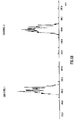
- a two channel Multiple Reaction Monitoring (“MRM”) experiment was set up.
- a first channel (“Channel 1”) monitored the transition of Reserpine parent ions having a mass to charge ratio 609 fragmenting into daughter ions having a mass to charge ratio of 195.
- a second channel (“Channel 2”) monitored a non-existent transition of ions having a mass to charge ratio of 612 fragmenting into ions having a mass to charge ratio of 195.
- the second channel was therefore a dummy channel and ideally no signal should be observed.
- the quadrupole mass filter was scanned over 4 Daltons in 0.5 seconds. As can be seen from Fig.
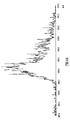
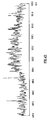
- Fig. 6A shows a mass peak at mass to charge ratio 165 which was obtained conventionally without applying a travelling DC potential wave to the collision cell 1 and Fig. 6B shows a corresponding mass peak obtained according to the preferred embodiment when a travelling DC potential wave was applied to the collision cell 1.
- the detected signal when a repeating DC waveform was applied to the electrodes 2 of the collision cell 1 has a pulsed nature and this advantageously enables a phase lock amplifier to be used.
- the two mass spectra were taken at a scan speed of 20 Daltons per second and correspond to the most intense daughter ion of Verapamil. Verapamil parent ions have a mass of 455 daltons.
- the collision energy was set to be 29 eV and the travelling wave voltage, when applied, was 0.5 V and the travelling wave velocity was 11 m/s.
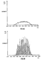
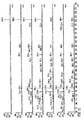
- Figs. 7A and 7B show part of a parent ion scan of Verapamil with and without a travelling DC potential wave applied to the collision cell 1.
- the scanning speed was 1000 Daltons per second and when applied the travelling DC potential wave had a velocity of 300 m/s with a pulse voltage of 5 V.
- Fig. 7A obtained according to the preferred embodiment with Fig. 7B obtained conventionally there is a significant improvement in the quality of the observed mass spectrum when a travelling DC potential wave was applied to the collision cell 1 according to the preferred embodiment.
- Figs. 8-12 show CID MS/MS data for different compounds at different collision energies with a travelling DC potential wave at two different travelling wave velocities (150 m/s and 1500 m/s).
- the mass spectra shown in Figs. 8-12 were all obtained using a collision cell 1 comprised of a stack of 122 ring electrodes each 0.5 mm thick and spaced apart by 1.0 mm. The central aperture of each ring was 5.0 mm diameter and the total length of ring stack was 182 mm. A 2.75 MHz RF voltage was applied between neighbouring rings to radially confine the ion beam within the collision cell 1. The pressure in the collision cell 1 was approximately 3.4 x 10 -3 mbar.
- the travelling wave which was applied comprised a regular periodic pulse of constant amplitude and velocity.
- the travelling wave was generated by applying a transient DC voltage to a pair of ring electrodes and every subsequent ring pair displaced by seven ring pairs along the ring stack. In each ring pair one electrode was maintained at a positive phase of the RF voltage and the other the negative.
- One wavelength of the waveform therefore consisted of two rings with a raised (transient) DC potential followed by twelve rings held at lower (normal) potentials.
- the wavelength ⁇ was equivalent to 14 rings (21 mm) and the collision cell 1 therefore had a length equivalent to approximately 5.8 ⁇ .
- the travelling DC potential wave was generated by applying a transient 10 V voltage to each pair of ring electrodes for a given time t before moving the applied voltage to the next pair of ring electrodes. This sequence was repeated uniformly along the length of the collision cell 1.
- V wave ⁇ /t was equal to 3mm/t where t is the time that the transient DC voltage was applied to an electrode.
- the data shows that at relatively low travelling DC wave velocities (e.g. 150 m/s) the collision energy determines the nature of the MS/MS spectrum and optimises at different collision energies for different parent ion masses. However, at higher travelling DC wave velocities (e.g. 1500 m/s) relatively high collision energy is not required for some ions and a relatively fast travelling wave is sufficient to effectively fragment all parent ions irrespective of their mass.
- travelling DC wave velocities e.g. 150 m/s
- relatively high collision energy is not required for some ions and a relatively fast travelling wave is sufficient to effectively fragment all parent ions irrespective of their mass.
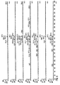
- Figs. 8A-8G show fragmentation mass spectra obtained from Verapamil (m/z 455) using different collision energies and two different travelling DC wave velocities.
- the travelling DC wave velocity was 150 m/s for the mass spectra shown in Figs. 8A-8E and 1500 m/s for the mass spectra shown in Figs. 8F and 8G.
- the pulse voltage was 10V and the gas cell pressure was 3.4 x 10 -3 mbar.
- the collision energy was 9 eV for the mass spectrum shown in Fig. 8A, 20 eV for the mass spectrum shown in Fig. 8B, 26 eV for the mass spectrum shown in Fig. 8C, 29 eV for the mass spectrum shown in Fig. 8D, 39 eV for the mass spectrum shown in Fig. 8E, 2 eV for the mass spectrum shown in Fig. 8F and 10 eV for the mass spectrum shown in Fig. 8G.
- Figs. 9A-9G show fragmentation mass spectra obtained from Diphenhydramine (m/z 256) using different collision energies and two different travelling DC wave velocities.
- the travelling DC wave velocity was 150 m/s for the mass spectra shown in Figs. 9A-9E and 1500 m/s for the mass spectra shown in Fig. 9F and 9G.
- the pulse voltage was 10V and the gas cell pressure 3.4 x 10 -3 mbar.
- the collision energy was 9 eV for the mass spectrum shown in Fig. 9A, 20 eV for the mass spectrum shown in Fig. 9B, 26 eV for the mass spectrum shown in Fig. 9C, 29 eV for the mass spectrum shown in Fig.
- Diphenhydramine is unusual in that it fragments exceptionally easily. It is sometimes used as a test compound to show how gentle a source is.
- Figs. 10A-10G show fragmentation mass spectra obtained from Terfenadine (m/z 472) using different collision energies and two different travelling DC wave velocities.
- the travelling DC wave velocity was 150 m/s for the mass spectra shown in Figs. 10A-10E and 1500 m/s for the mass spectra shown in Figs. 10F and 10G
- the pulse voltage was 10V and the gas cell pressure 3.4 x 10 -3 mbar.
- the collision energy was 9 eV for the mass spectrum shown in Fig. 10A, 20 eV for the mass spectrum shown in Fig. 10B, 26 eV for the mass spectrum shown in Fig. 10C, 29 eV for the mass spectrum shown in Fig. 10D, 39 eV for the mass spectrum shown in Fig. 10E, 2 eV for the mass spectrum shown in Fig. 10F and 10 eV for the mass spectrum shown in Fig. 10G.
- Figs. 11A-11G show fragmentation mass spectra obtained from Sulfadimethoxine (m/z 311) using different collision energies and two different travelling DC wave velocities.
- the travelling DC wave velocity was 150 m/s for the mass spectra shown in Figs. 11A-11E and 1500 m/s for the mass spectra shown in Figs 11F and 11G.
- the pulse voltage was 10V and the gas cell pressure 3.4 x 10 -3 mbar.
- the collision energy was 9 eV for the mass spectrum shown in Fig. 11A, 20 eV for the mass spectrum shown in Fig. 11B, 26 eV for the mass spectrum shown in Fig. 11C, 29 eV for the mass spectrum shown in Fig. 11D, 39 eV for the mass spectrum shown in Fig. 11E, 2 eV for the mass spectrum shown in Fig. 11F and 10 eV for the mass spectrum shown in Fig. 11G.
- Figs. 12A-12G show fragmentation mass spectra obtained from Reserpine (m/z 609) using different collision energies and two different travelling DC wave velocities.
- the travelling DC wave velocity was 150 m/s for the mass spectra shown in Figs. 12A-12E and 1500 m/s for the mass spectra shown in Fig. 12F and 12G.
- the pulse voltage was 10V and the gas cell pressure 3.4 x 10 -3 mbar.
- the collision energy was 9 eV for the mass spectrum shown in Fig. 12A, 20 eV for the mass spectrum shown in Fig. 12B, 26 eV for the mass spectrum shown in Fig. 12C, 29 eV for the mass spectrum shown in Fig. 12D, 39 eV for the mass spectrum shown in Fig. 12E, 2 eV for the mass spectrum shown in Fig. 12F and 10 eV for the mass spectrum shown in Fig. 12G.
Landscapes
- Chemical & Material Sciences (AREA)
- Analytical Chemistry (AREA)
- Chemical Kinetics & Catalysis (AREA)
- Other Investigation Or Analysis Of Materials By Electrical Means (AREA)
- Electron Tubes For Measurement (AREA)
- Sampling And Sample Adjustment (AREA)
Applications Claiming Priority (4)
| Application Number | Priority Date | Filing Date | Title |
|---|---|---|---|
| GB0212511 | 2002-05-30 | ||
| GB0212511A GB0212511D0 (en) | 2002-05-30 | 2002-05-30 | Mass spectrometer |
| GB0308346A GB0308346D0 (en) | 2002-05-30 | 2003-04-11 | Mass spectrometer |
| GB0308346 | 2003-04-11 |
Publications (3)
| Publication Number | Publication Date |
|---|---|
| EP1367632A2 true EP1367632A2 (fr) | 2003-12-03 |
| EP1367632A3 EP1367632A3 (fr) | 2004-09-29 |
| EP1367632B1 EP1367632B1 (fr) | 2007-09-05 |
Family
ID=26247076
Family Applications (1)
| Application Number | Title | Priority Date | Filing Date |
|---|---|---|---|
| EP03253411A Expired - Lifetime EP1367632B1 (fr) | 2002-05-30 | 2003-05-30 | Spectromètre de masse |
Country Status (5)
| Country | Link |
|---|---|
| EP (1) | EP1367632B1 (fr) |
| AT (1) | ATE372587T1 (fr) |
| CA (1) | CA2430527C (fr) |
| DE (1) | DE60316070T2 (fr) |
| GB (1) | GB2391698B (fr) |
Cited By (8)
| Publication number | Priority date | Publication date | Assignee | Title |
|---|---|---|---|---|
| EP1592042A3 (fr) * | 2004-04-30 | 2006-10-25 | Agilent Technologies, Inc. | Multipole inégalement segmenté |
| EP1763062A2 (fr) * | 2005-09-13 | 2007-03-14 | Agilent Technologies, Inc. | Chambre de collision multipolaire de gradient augmentée pour un coefficient d'utilisation plus élevé |
| DE102005044307A1 (de) * | 2005-09-16 | 2007-03-22 | Bruker Daltonik Gmbh | Ionisierung desorbierter Moleküle |
| WO2012127184A3 (fr) * | 2011-03-18 | 2012-12-20 | Shimadzu Corporation | Appareil et procédé d'analyse d'ions |
| WO2013005058A1 (fr) * | 2011-07-06 | 2013-01-10 | Micromass Uk Limited | Guide d'ions couplé à une source d'ions maldi |
| EP2395538A4 (fr) * | 2009-02-05 | 2015-12-30 | Shimadzu Corp | Spectromètre de masse en tandem |
| EP2223329B1 (fr) * | 2007-11-23 | 2018-09-12 | Micromass UK Limited | Dispositif de réaction ion-ion |
| EP3971944A1 (fr) * | 2020-09-22 | 2022-03-23 | Thermo Finnigan LLC | Procédés et appareil de transfert d'ions par groupage d'ions |
Families Citing this family (2)
| Publication number | Priority date | Publication date | Assignee | Title |
|---|---|---|---|---|
| GB0426900D0 (en) | 2004-12-08 | 2005-01-12 | Micromass Ltd | Mass spectrometer |
| GB201504817D0 (en) | 2015-03-23 | 2015-05-06 | Micromass Ltd | Pre-filter fragmentation |
Family Cites Families (6)
| Publication number | Priority date | Publication date | Assignee | Title |
|---|---|---|---|---|
| US5206506A (en) * | 1991-02-12 | 1993-04-27 | Kirchner Nicholas J | Ion processing: control and analysis |
| WO1994001883A1 (fr) * | 1992-07-01 | 1994-01-20 | United States Department Of Energy | Procede de selection de particules par discrimination |
| AU6653296A (en) * | 1995-08-11 | 1997-03-12 | Mds Health Group Limited | Spectrometer with axial field |
| GB2341270A (en) * | 1998-09-02 | 2000-03-08 | Shimadzu Corp | Mass spectrometer having ion lens composed of plurality of virtual rods comprising plurality of electrodes |
| CA2391140C (fr) * | 2001-06-25 | 2008-10-07 | Micromass Limited | Spectrometre de masse |
| CA2391148C (fr) * | 2001-06-25 | 2008-02-19 | Micromass Limited | Spectrometre de masse |
-
2003
- 2003-05-30 CA CA2430527A patent/CA2430527C/fr not_active Expired - Lifetime
- 2003-05-30 GB GB0312482A patent/GB2391698B/en not_active Expired - Lifetime
- 2003-05-30 AT AT03253411T patent/ATE372587T1/de not_active IP Right Cessation
- 2003-05-30 EP EP03253411A patent/EP1367632B1/fr not_active Expired - Lifetime
- 2003-05-30 DE DE60316070T patent/DE60316070T2/de not_active Expired - Lifetime
Cited By (13)
| Publication number | Priority date | Publication date | Assignee | Title |
|---|---|---|---|---|
| EP1592042A3 (fr) * | 2004-04-30 | 2006-10-25 | Agilent Technologies, Inc. | Multipole inégalement segmenté |
| EP1763062A2 (fr) * | 2005-09-13 | 2007-03-14 | Agilent Technologies, Inc. | Chambre de collision multipolaire de gradient augmentée pour un coefficient d'utilisation plus élevé |
| DE102005044307A1 (de) * | 2005-09-16 | 2007-03-22 | Bruker Daltonik Gmbh | Ionisierung desorbierter Moleküle |
| DE102005044307B4 (de) * | 2005-09-16 | 2008-04-17 | Bruker Daltonik Gmbh | Ionisierung desorbierter Moleküle |
| US7504640B2 (en) | 2005-09-16 | 2009-03-17 | Bruker Daltonik, Gmbh | Ionization of desorbed molecules |
| EP2223329B1 (fr) * | 2007-11-23 | 2018-09-12 | Micromass UK Limited | Dispositif de réaction ion-ion |
| EP2395538A4 (fr) * | 2009-02-05 | 2015-12-30 | Shimadzu Corp | Spectromètre de masse en tandem |
| WO2012127184A3 (fr) * | 2011-03-18 | 2012-12-20 | Shimadzu Corporation | Appareil et procédé d'analyse d'ions |
| US8981287B2 (en) | 2011-03-18 | 2015-03-17 | Shimadzu Corporation | Ion analysis apparatus and method |
| WO2013005058A1 (fr) * | 2011-07-06 | 2013-01-10 | Micromass Uk Limited | Guide d'ions couplé à une source d'ions maldi |
| GB2493602B (en) * | 2011-07-06 | 2016-04-06 | Micromass Ltd | Ion guide coupled to MALDI ion source |
| EP3971944A1 (fr) * | 2020-09-22 | 2022-03-23 | Thermo Finnigan LLC | Procédés et appareil de transfert d'ions par groupage d'ions |
| US11600480B2 (en) | 2020-09-22 | 2023-03-07 | Thermo Finnigan Llc | Methods and apparatus for ion transfer by ion bunching |
Also Published As
| Publication number | Publication date |
|---|---|
| EP1367632A3 (fr) | 2004-09-29 |
| GB2391698A (en) | 2004-02-11 |
| CA2430527C (fr) | 2012-03-27 |
| DE60316070D1 (de) | 2007-10-18 |
| GB0312482D0 (en) | 2003-07-09 |
| EP1367632B1 (fr) | 2007-09-05 |
| DE60316070T2 (de) | 2008-06-05 |
| ATE372587T1 (de) | 2007-09-15 |
| CA2430527A1 (fr) | 2003-11-30 |
| GB2391698B (en) | 2004-07-21 |
Similar Documents
| Publication | Publication Date | Title |
|---|---|---|
| US6800846B2 (en) | Mass spectrometer | |
| CA2430531C (fr) | Spectrometre de masse | |
| US7095013B2 (en) | Mass spectrometer | |
| US6794641B2 (en) | Mass spectrometer | |
| CA2588804C (fr) | Spectrometre de masse | |
| US9012840B2 (en) | Mass spectrometer | |
| CA2861514C (fr) | Spectrometre de masse | |
| EP1378930B1 (fr) | Spectromètre de masse | |
| US8519328B2 (en) | Mass spectrometer | |
| US20050023453A1 (en) | Mass spectrometer | |
| GB2455593A (en) | A mass analyzer utilising a plurality of axial pseudo-potential barriers | |
| CA2696513A1 (fr) | Dispositif tandem de piegeage d'ions | |
| WO2009007739A2 (fr) | Spectromètre de masse | |
| EP1367632B1 (fr) | Spectromètre de masse | |
| CA2436583C (fr) | Spectrometre de masse | |
| GB2398925A (en) | Mass spectrometer comprising fragemetation device |
Legal Events
| Date | Code | Title | Description |
|---|---|---|---|
| PUAI | Public reference made under article 153(3) epc to a published international application that has entered the european phase |
Free format text: ORIGINAL CODE: 0009012 |
|
| AK | Designated contracting states |
Kind code of ref document: A2 Designated state(s): AT BE BG CH CY CZ DE DK EE ES FI FR GB GR HU IE IT LI LU MC NL PT RO SE SI SK TR |
|
| AX | Request for extension of the european patent |
Extension state: AL LT LV MK |
|
| RAP1 | Party data changed (applicant data changed or rights of an application transferred) |
Owner name: MICROMASS UK LIMITED |
|
| PUAL | Search report despatched |
Free format text: ORIGINAL CODE: 0009013 |
|
| AK | Designated contracting states |
Kind code of ref document: A3 Designated state(s): AT BE BG CH CY CZ DE DK EE ES FI FR GB GR HU IE IT LI LU MC NL PT RO SE SI SK TR |
|
| AX | Request for extension of the european patent |
Extension state: AL LT LV MK |
|
| RIC1 | Information provided on ipc code assigned before grant |
Ipc: 7H 01J 49/40 A Ipc: 7H 01J 49/42 B |
|
| 17P | Request for examination filed |
Effective date: 20050317 |
|
| AKX | Designation fees paid |
Designated state(s): AT BE BG CH CY CZ DE DK EE ES FI FR GB GR HU IE IT LI LU MC NL PT RO SE SI SK TR |
|
| GRAP | Despatch of communication of intention to grant a patent |
Free format text: ORIGINAL CODE: EPIDOSNIGR1 |
|
| RBV | Designated contracting states (corrected) |
Designated state(s): AT BE BG CH CY CZ DE DK EE ES FI FR GR HU IE IT LI LU MC NL PT RO SE SI SK TR |
|
| GRAC | Information related to communication of intention to grant a patent modified |
Free format text: ORIGINAL CODE: EPIDOSCIGR1 |
|
| GRAS | Grant fee paid |
Free format text: ORIGINAL CODE: EPIDOSNIGR3 |
|
| GRAA | (expected) grant |
Free format text: ORIGINAL CODE: 0009210 |
|
| AK | Designated contracting states |
Kind code of ref document: B1 Designated state(s): AT BE BG CH CY CZ DE DK EE ES FI FR GR HU IE IT LI LU MC NL PT RO SE SI SK TR |
|
| REG | Reference to a national code |
Ref country code: CH Ref legal event code: EP |
|
| REF | Corresponds to: |
Ref document number: 60316070 Country of ref document: DE Date of ref document: 20071018 Kind code of ref document: P |
|
| REG | Reference to a national code |
Ref country code: IE Ref legal event code: FG4D |
|
| PG25 | Lapsed in a contracting state [announced via postgrant information from national office to epo] |
Ref country code: ES Free format text: LAPSE BECAUSE OF FAILURE TO SUBMIT A TRANSLATION OF THE DESCRIPTION OR TO PAY THE FEE WITHIN THE PRESCRIBED TIME-LIMIT Effective date: 20071216 Ref country code: FI Free format text: LAPSE BECAUSE OF FAILURE TO SUBMIT A TRANSLATION OF THE DESCRIPTION OR TO PAY THE FEE WITHIN THE PRESCRIBED TIME-LIMIT Effective date: 20070905 |
|
| PG25 | Lapsed in a contracting state [announced via postgrant information from national office to epo] |
Ref country code: CH Free format text: LAPSE BECAUSE OF FAILURE TO SUBMIT A TRANSLATION OF THE DESCRIPTION OR TO PAY THE FEE WITHIN THE PRESCRIBED TIME-LIMIT Effective date: 20070905 Ref country code: LI Free format text: LAPSE BECAUSE OF FAILURE TO SUBMIT A TRANSLATION OF THE DESCRIPTION OR TO PAY THE FEE WITHIN THE PRESCRIBED TIME-LIMIT Effective date: 20070905 Ref country code: AT Free format text: LAPSE BECAUSE OF FAILURE TO SUBMIT A TRANSLATION OF THE DESCRIPTION OR TO PAY THE FEE WITHIN THE PRESCRIBED TIME-LIMIT Effective date: 20070905 |
|
| NLV1 | Nl: lapsed or annulled due to failure to fulfill the requirements of art. 29p and 29m of the patents act | ||
| PG25 | Lapsed in a contracting state [announced via postgrant information from national office to epo] |
Ref country code: BE Free format text: LAPSE BECAUSE OF FAILURE TO SUBMIT A TRANSLATION OF THE DESCRIPTION OR TO PAY THE FEE WITHIN THE PRESCRIBED TIME-LIMIT Effective date: 20070905 |
|
| REG | Reference to a national code |
Ref country code: CH Ref legal event code: PL |
|
| PG25 | Lapsed in a contracting state [announced via postgrant information from national office to epo] |
Ref country code: NL Free format text: LAPSE BECAUSE OF FAILURE TO SUBMIT A TRANSLATION OF THE DESCRIPTION OR TO PAY THE FEE WITHIN THE PRESCRIBED TIME-LIMIT Effective date: 20070905 Ref country code: GR Free format text: LAPSE BECAUSE OF FAILURE TO SUBMIT A TRANSLATION OF THE DESCRIPTION OR TO PAY THE FEE WITHIN THE PRESCRIBED TIME-LIMIT Effective date: 20071206 |
|
| EN | Fr: translation not filed | ||
| PG25 | Lapsed in a contracting state [announced via postgrant information from national office to epo] |
Ref country code: PT Free format text: LAPSE BECAUSE OF FAILURE TO SUBMIT A TRANSLATION OF THE DESCRIPTION OR TO PAY THE FEE WITHIN THE PRESCRIBED TIME-LIMIT Effective date: 20080206 Ref country code: CZ Free format text: LAPSE BECAUSE OF FAILURE TO SUBMIT A TRANSLATION OF THE DESCRIPTION OR TO PAY THE FEE WITHIN THE PRESCRIBED TIME-LIMIT Effective date: 20070905 Ref country code: SK Free format text: LAPSE BECAUSE OF FAILURE TO SUBMIT A TRANSLATION OF THE DESCRIPTION OR TO PAY THE FEE WITHIN THE PRESCRIBED TIME-LIMIT Effective date: 20070905 |
|
| PG25 | Lapsed in a contracting state [announced via postgrant information from national office to epo] |
Ref country code: SE Free format text: LAPSE BECAUSE OF FAILURE TO SUBMIT A TRANSLATION OF THE DESCRIPTION OR TO PAY THE FEE WITHIN THE PRESCRIBED TIME-LIMIT Effective date: 20071205 Ref country code: RO Free format text: LAPSE BECAUSE OF FAILURE TO SUBMIT A TRANSLATION OF THE DESCRIPTION OR TO PAY THE FEE WITHIN THE PRESCRIBED TIME-LIMIT Effective date: 20070905 |
|
| PLBE | No opposition filed within time limit |
Free format text: ORIGINAL CODE: 0009261 |
|
| STAA | Information on the status of an ep patent application or granted ep patent |
Free format text: STATUS: NO OPPOSITION FILED WITHIN TIME LIMIT |
|
| PG25 | Lapsed in a contracting state [announced via postgrant information from national office to epo] |
Ref country code: DK Free format text: LAPSE BECAUSE OF FAILURE TO SUBMIT A TRANSLATION OF THE DESCRIPTION OR TO PAY THE FEE WITHIN THE PRESCRIBED TIME-LIMIT Effective date: 20070905 |
|
| 26N | No opposition filed |
Effective date: 20080606 |
|
| PG25 | Lapsed in a contracting state [announced via postgrant information from national office to epo] |
Ref country code: FR Free format text: LAPSE BECAUSE OF FAILURE TO SUBMIT A TRANSLATION OF THE DESCRIPTION OR TO PAY THE FEE WITHIN THE PRESCRIBED TIME-LIMIT Effective date: 20080502 |
|
| PG25 | Lapsed in a contracting state [announced via postgrant information from national office to epo] |
Ref country code: MC Free format text: LAPSE BECAUSE OF NON-PAYMENT OF DUE FEES Effective date: 20080531 |
|
| PG25 | Lapsed in a contracting state [announced via postgrant information from national office to epo] |
Ref country code: IE Free format text: LAPSE BECAUSE OF NON-PAYMENT OF DUE FEES Effective date: 20080530 Ref country code: EE Free format text: LAPSE BECAUSE OF FAILURE TO SUBMIT A TRANSLATION OF THE DESCRIPTION OR TO PAY THE FEE WITHIN THE PRESCRIBED TIME-LIMIT Effective date: 20070905 |
|
| PG25 | Lapsed in a contracting state [announced via postgrant information from national office to epo] |
Ref country code: SI Free format text: LAPSE BECAUSE OF FAILURE TO SUBMIT A TRANSLATION OF THE DESCRIPTION OR TO PAY THE FEE WITHIN THE PRESCRIBED TIME-LIMIT Effective date: 20070905 |
|
| PG25 | Lapsed in a contracting state [announced via postgrant information from national office to epo] |
Ref country code: CY Free format text: LAPSE BECAUSE OF FAILURE TO SUBMIT A TRANSLATION OF THE DESCRIPTION OR TO PAY THE FEE WITHIN THE PRESCRIBED TIME-LIMIT Effective date: 20070905 |
|
| PG25 | Lapsed in a contracting state [announced via postgrant information from national office to epo] |
Ref country code: BG Free format text: LAPSE BECAUSE OF FAILURE TO SUBMIT A TRANSLATION OF THE DESCRIPTION OR TO PAY THE FEE WITHIN THE PRESCRIBED TIME-LIMIT Effective date: 20071205 |
|
| PG25 | Lapsed in a contracting state [announced via postgrant information from national office to epo] |
Ref country code: HU Free format text: LAPSE BECAUSE OF FAILURE TO SUBMIT A TRANSLATION OF THE DESCRIPTION OR TO PAY THE FEE WITHIN THE PRESCRIBED TIME-LIMIT Effective date: 20080306 Ref country code: LU Free format text: LAPSE BECAUSE OF NON-PAYMENT OF DUE FEES Effective date: 20080530 |
|
| PG25 | Lapsed in a contracting state [announced via postgrant information from national office to epo] |
Ref country code: TR Free format text: LAPSE BECAUSE OF FAILURE TO SUBMIT A TRANSLATION OF THE DESCRIPTION OR TO PAY THE FEE WITHIN THE PRESCRIBED TIME-LIMIT Effective date: 20070905 |
|
| PG25 | Lapsed in a contracting state [announced via postgrant information from national office to epo] |
Ref country code: IT Free format text: LAPSE BECAUSE OF NON-PAYMENT OF DUE FEES Effective date: 20080531 |
|
| PGFP | Annual fee paid to national office [announced via postgrant information from national office to epo] |
Ref country code: DE Payment date: 20220420 Year of fee payment: 20 |
|
| REG | Reference to a national code |
Ref country code: DE Ref legal event code: R071 Ref document number: 60316070 Country of ref document: DE |