EP1390207B1 - Imprimantes a jet d'encre et procedes - Google Patents
Imprimantes a jet d'encre et procedes Download PDFInfo
- Publication number
- EP1390207B1 EP1390207B1 EP02728002A EP02728002A EP1390207B1 EP 1390207 B1 EP1390207 B1 EP 1390207B1 EP 02728002 A EP02728002 A EP 02728002A EP 02728002 A EP02728002 A EP 02728002A EP 1390207 B1 EP1390207 B1 EP 1390207B1
- Authority
- EP
- European Patent Office
- Prior art keywords
- nozzle
- ink drops
- charging
- substrate
- liquid ink
- Prior art date
- Legal status (The legal status is an assumption and is not a legal conclusion. Google has not performed a legal analysis and makes no representation as to the accuracy of the status listed.)
- Expired - Lifetime
Links
- 238000000034 method Methods 0.000 title claims abstract description 35
- 239000000758 substrate Substances 0.000 claims abstract description 63
- 239000007788 liquid Substances 0.000 claims abstract description 53
- 238000007639 printing Methods 0.000 claims abstract description 35
- 230000015572 biosynthetic process Effects 0.000 claims abstract description 29
- 238000007599 discharging Methods 0.000 claims abstract description 8
- 238000003384 imaging method Methods 0.000 claims description 37
- 230000003287 optical effect Effects 0.000 claims description 8
- 238000000926 separation method Methods 0.000 claims description 7
- 238000005755 formation reaction Methods 0.000 description 22
- 238000010586 diagram Methods 0.000 description 11
- 230000005284 excitation Effects 0.000 description 9
- 238000005286 illumination Methods 0.000 description 8
- 238000005259 measurement Methods 0.000 description 8
- 238000010276 construction Methods 0.000 description 5
- 230000001133 acceleration Effects 0.000 description 3
- 238000000151 deposition Methods 0.000 description 3
- 230000005684 electric field Effects 0.000 description 3
- 238000007641 inkjet printing Methods 0.000 description 3
- 238000012986 modification Methods 0.000 description 3
- 230000004048 modification Effects 0.000 description 3
- 238000012360 testing method Methods 0.000 description 3
- 230000015556 catabolic process Effects 0.000 description 2
- 238000012937 correction Methods 0.000 description 2
- 230000008021 deposition Effects 0.000 description 2
- 230000007257 malfunction Effects 0.000 description 2
- 229910002056 binary alloy Inorganic materials 0.000 description 1
- 230000003247 decreasing effect Effects 0.000 description 1
- 238000013461 design Methods 0.000 description 1
- 230000000694 effects Effects 0.000 description 1
- 238000012544 monitoring process Methods 0.000 description 1
- 238000005457 optimization Methods 0.000 description 1
- 238000012545 processing Methods 0.000 description 1
- 230000026676 system process Effects 0.000 description 1
- 238000011144 upstream manufacturing Methods 0.000 description 1
Images

Classifications
-
- B—PERFORMING OPERATIONS; TRANSPORTING
- B41—PRINTING; LINING MACHINES; TYPEWRITERS; STAMPS
- B41J—TYPEWRITERS; SELECTIVE PRINTING MECHANISMS, i.e. MECHANISMS PRINTING OTHERWISE THAN FROM A FORME; CORRECTION OF TYPOGRAPHICAL ERRORS
- B41J2/00—Typewriters or selective printing mechanisms characterised by the printing or marking process for which they are designed
- B41J2/005—Typewriters or selective printing mechanisms characterised by the printing or marking process for which they are designed characterised by bringing liquid or particles selectively into contact with a printing material
- B41J2/01—Ink jet
- B41J2/07—Ink jet characterised by jet control
- B41J2/105—Ink jet characterised by jet control for binary-valued deflection
-
- B—PERFORMING OPERATIONS; TRANSPORTING
- B41—PRINTING; LINING MACHINES; TYPEWRITERS; STAMPS
- B41J—TYPEWRITERS; SELECTIVE PRINTING MECHANISMS, i.e. MECHANISMS PRINTING OTHERWISE THAN FROM A FORME; CORRECTION OF TYPOGRAPHICAL ERRORS
- B41J2/00—Typewriters or selective printing mechanisms characterised by the printing or marking process for which they are designed
- B41J2/005—Typewriters or selective printing mechanisms characterised by the printing or marking process for which they are designed characterised by bringing liquid or particles selectively into contact with a printing material
- B41J2/01—Ink jet
- B41J2/07—Ink jet characterised by jet control
- B41J2/075—Ink jet characterised by jet control for many-valued deflection
- B41J2/08—Ink jet characterised by jet control for many-valued deflection charge-control type
- B41J2/09—Deflection means
Definitions
- the present invention relates to ink jet printers and methods of printing by ink jets.
- the present invention is particularly useful in the apparatus and methods described in our prior U.S. Patents 5,969,733 , 6,003,980 and 6,106,107 , and also in US-A-5 410 342 .
- the invention is therefore described below with regard to such apparatus and methods, but it will be appreciated that the invention could also be used in other apparatus and methods.
- Ink jet printers are based on forming drops of liquid ink and selectively depositing the ink drops on a substrate.
- the known ink jet printers generally fall into two categories: drop-on-demand printers, and continuous-jet printers.
- Drop-on-demand printers selectively form and deposit the ink jet drops on the substrate as and when demanded by a control signal from an external data source.
- Such systems typically use nozzles having relatively large openings, ranging from 30 to 100 ⁇ m.
- Continuous-jet printers are stimulated by a perturbation device, such as a piezoelectric transducer, to form the ink drops from a continuous ink jet filament at a rate determined by the perturbation device.
- the drops are selectively charged and deflected to direct them onto the substrate according to the desired pattern to be printed.
- Continuous jet printers are divided into two types of systems: binary, and multi-level.
- binary systems the drops are either charged or uncharged and, accordingly, either reach or do not reach the substrate at a single predetermined position.
- multi-level systems the drops can receive a large number of charge levels and, accordingly, can generate a large number of print positions.
- drop formation depends on many factors associated with the ink rhelogy (e.g. viscosity, surface tension), the ink flow conditions (e.g. jet diameter, jet velocity), and the characteristics of the perturbation (e.g. frequency and amplitude of the excitation).
- ink rhelogy e.g. viscosity, surface tension
- the ink flow conditions e.g. jet diameter, jet velocity
- the characteristics of the perturbation e.g. frequency and amplitude of the excitation.
- drop formation is a fast process, occurring in the time frame of a few microseconds.
- variations are possible in the exact timing of the drop break-off. These timing variations can cause incorrect charging of drops if the electrical field responsible for drop charging is turned-on, turned-off, or changed to a new level, during the drop break-off itself. Therefore it is necessary to keep the data pulse precisely in-phase relative to the drop break-off timing, in order to obtain accurate drop charging and printing.
- Drop velocity (or jet speed) errors may be produced by many different factors, such as those associated with the ink rhelogy and/or the ink flow conditions. Such errors may be corrected by changing the drop charging voltage applied to the ink drops since the amount of deflection experienced by the ink drops before impinging the substrate depends on the drop velocity, the voltage applied to the deflector plates electric field, and the drop charge.
- Satellites are characterized by volumes which are much smaller (typically by more than one order of magnitude) than the basic drop volume, i.e. the volume within the drop desired to be printed.
- the basic drop volume i.e. the volume within the drop desired to be printed.
- satellites carry a charge similar to the charge carried by the basic drop.
- the acceleration experienced by charged drops in an electrical field is inversely proportional to their masses. Since the mass of the satellite is much smaller than the mass of the basic drop, satellites will experience a much stronger acceleration inside the deflection field, and may therefore impinge against the deflecting plates. This could result in an electrical breakdown condition or other malfunction of the printer.
- GB-A-1 124 163 there is described a method of operating printing apparatus for printing a desired pattern on a substrate, according to the preamble of claim 1.
- a printing apparatus for printing a desired pattern on a substrate according to the preamble of claim 9 is also known from GB-A-1 124 163 .
- An object of the present invention is to provide a method of ink jet printing, and also an ink jet printing apparatus, having advantages in one or more of the above respects.
- the method of the invention is characterized by the features claimed in the characterizing part of claim 1 and the invention provides a printing apparatus according to the characterizing part of claim 9.
- a method of operating printing apparatus for printing a desired pattern on a substrate by discharging a continuous stream of liquid ink drops from a nozzle along the nozzle axis towards the substrate; and selectively charging said liquid ink drops with multi-level charges for selectively deflecting them different amounts with respect to the nozzle axis to thereby direct some of the liquid ink drops to different locations on the substrate for printing said desired pattern thereon, while other liquid ink drops not to be printed are intercepted by a gutter before reaching the substrate; said method comprising:
- the charging phasing errors are detected and are corrected by correcting the time delay between the respective charging pulse and the physical drop separation in the stream exiting from the nozzle.
- velocity errors are detected and are corrected by modifying the levels of the charges, applied to the ink drops.
- two streams of ink drops are optically sensed on the fly by illuminating them with stroboscopic light at the frequency of the drop formation.
- At least two optical sensor devices are used for sensing the liquid ink drops of each of said streams, said sensor devices having sensor axes at a predetermined angle to each other; and the outputs of said sensor devices, including said predetermined angle of their sensor axes, are used to compute X-axis and Y-axis deviations of the respective stream of ink drops from the respective nozzle axis in the direction parallel to said row of nozzles, and in the direction perpendicular to said row of nozzles, respectively.
- each of the optical sensors includes a camera having an imaging lens.
- the computed X-axis deviation for a particular nozzle is corrected by adjusting the charging voltages for the respective nozzle.
- the computed X-axis deviation for a particular nozzle is corrected by adjusting the timing of said input data to the respective nozzle.
- printing apparatus for printing a desired pattern on a substrate, comprising: a nozzle for forming and discharging a continuous stream of liquid ink drops along the nozzle axis towards the substrate; charging plates for selectively charging the liquid ink drops with multi-level charges; deflecting plates for selectively deflecting the liquid ink drops different amounts with respect to the nozzle axis to thereby direct some of the liquid ink drops to different locations on the substrate for printing thereon the desired pattern; a gutter for intercepting, before reaching the substrate, the liquid ink drops not to be printed; a sensor device for sensing said ink drops discharged by said nozzle towards the substrate; and a control system for controlling said charging plates and said deflecting plates; characterized in that said control system controls said charging plates and said deflecting plates to divide the stream of ink drops discharged by said nozzle into two streams by charging pulses of two charging levels and of appropriate phases; and in that said control system also processes the output of said sensor device for determining, and
- the apparatus further comprises a stroboscopic illuminating device for illuminating the stream of drops discharged from the nozzle at the frequency of the drop formation; said sensor device including a video imaging device for imaging and displaying the stream of liquid ink drops discharged from the nozzle.
- the sensor devices are optical sensors, and said streams of ink drops are illuminated with stroboscopic light at the same frequency as the drop formation.
- each of the optical sensors includes a camera having an imaging lens.
- control system corrects said X-axis deviations for a particular nozzle by adjusting the charging voltages applied to the respective nozzle.
- control system corrects said Y-axis deviations for a particular nozzle by adjusting the timing of said input data to the respective nozzle.
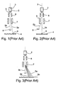
- Fig. 1 illustrates a simplified construction of a continuous-jet printer according to the prior art.
- the illustrated printer includes a nozzle 2 containing a reservoir of liquid ink directing the liquid ink in the form of a continuous jet along the nozzle axis 3 towards a substrate 4 for deposition thereon according to the desired pattern to be printed.
- Nozzle 2 includes a perturbator, such as a piezoelectric transducer, which converts the jet of liquid ink into a continuous stream of liquid ink drops 5 initially directed along the nozzle axis 3 towards the substrate 4, but selectively deflected according to the desired pattern to be printed on the substrate.
- a perturbator such as a piezoelectric transducer
- the selective deflection of the liquid ink drops 5 is effected first by a pair of charging plates 6 straddling the nozzle axis 3, and then by a pair of deflecting plates 7 also straddling the nozzle axis.
- the charging plates 6 selectively charge the drops 5 at the instant of drop break-off from the jet filament, and the deflecting plates 7 deflect the charged drops with respect to the nozzle axis 3.
- a gutter or catcher 8 between the deflecting plates 7 and the substrate 4 catches those liquid ink drops which are not to be deposited on the substrate 4. The so-caught drops are circulated back to the reservoir of the respective nozzle 2.
- the arrangement illustrated in Fig. 1 is a bi-level deflection arrangement in which the liquid ink drops 5 are either charged or not charged, and in which the gutter 8 is aligned with the nozzle axis 3 so as to receive the uncharged (free-fall) drops.
- the charged drops 5a are deflected so as to be deposited as a printed dot 9 on the substrate 4; whereas the uncharged (free-fall) drops 5b are caught by the gutter 8 and therefore do not reach the substrate 4.
- Fig. 2 illustrates a bi-level deflection printer of basically the same construction as described above with respect to Fig. 1 , except that the substrate 4 receives the uncharged drops 5a to be printed, whereas the gutter 8 receives the charged drops 5b not to be printed.
- the gutter 8 is located laterally of the nozzle axis 3, so as to receive the charged liquid ink drops 5b, whereas the uncharged (free-fall) drops 5a are deposited on the substrate 4 to produce the printed dots 9.
- Fig. 3 illustrates a prior art ink jet printer of a similar construction as in Fig. 1 , except that it utilizes a multi-level deflection arrangement, rather than a bi-level deflection arrangement.
- the basic difference in Fig. 3 (which also identifies the corresponding parts of Fig. 1 with the same reference numerals to facilitate understanding) is that, instead of utilizing the charging plates 6 for applying only two levels of charges to the liquid ink drops (charged or uncharged), in Fig. 3 the charging plates 6 apply any one of a plurality of charges to the drops in order to selectively deflect each drop a different amount from the nozzle axis 3, and thereby to generate a wide "fan" of printed drops, as shown at 9a-9n in Fig.
- the uncharged free-fall drops are the drops not to be printed and therefore received by the gutter 8
- the drops 5a to be printed are all charged drops which are deposited on the substrate 4 at various locations, as shown at 9a-9n, according to the multi-level charge received by the respective drop.
- the charged drop 5a to be deflected the longest distance is indicated by printed dot 9n in Fig. 3 .
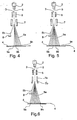
- Figs. 4-14 illustrate ink j et printers constructed in accordance with various aspects of the present invention.
- those parts of the ink jet printer which correspond to the prior art printer as described above with respect to Figs. 1-3 are identified generally by the same reference numerals.
- Fig. 4 illustrates a multi-level deflection arrangement wherein the charging plates 6 apply a multi-level charge to the drops 5 exiting from the nozzle 2 such that the deflecting plates 7 deflect the drops 5a to be received on the substrate 4 to any one of a plurality of locations thereon, as shown by print dots 9a-9n, according to the charge applied to the respective drops, whereas the drops 5b not to reach the substrate 4 are caught in the gutter 8.
- the drops 5a to be deposited on the substrate 4 are either uncharged, or charged to a selected one of a plurality of charge levels of one polarity; whereas the drops 5b not to be printed on the substrate 4 are charged to a level of the opposite sign.
- the substrate 4 will receive, as printed dots, the un-charged (free-fall) drops to produce the printed dot 9a along the nozzle axis 3, and also the selected one of the charged drops, charged to a selected level of one polarity, which drops will be deposited on the substrate 4 to produce the printed dots 9b-9n according to the selected charge.
- the drops which are charged with the opposite sign are deflected in the opposite direction from the nozzle axis 3 towards the gutter 8 so as to be caught by the gutter before reaching the substrate 4, as shown by drops 5b in Fig. 4 .
- the arrangement illustrated in Fig. 4 has a number of advantages.
- One important advantage is that it enables a wider fan of printing drops to be produced without increasing the charge to be applied to the drop to experience the largest deflection.
- the outside printed dot 9n is significantly closer to the nozzle axis 3 than the outside printed dot 9n in Fig. 3 .
- a further important advantage is that the arrangement illustrated in Fig. 4 enables the uncharged or free-fall drops to be used for calibration purposes since those drops do reach the substrate 4, as indicated by printed dot 9a in Fig. 4 ; whereas the uncharged drops in the prior art arrangement illustrated in Fig. 3 were received by the gutter 8 and therefore could not be effectively used for calibration purposes.
- the description below illustrates various ways in which the uncharged free-fall drops may be used for calibration purposes.
- Fig. 5 illustrates an arrangement, similar to that of Fig. 4 and therefore also uses the same reference numerals for identifying corresponding parts.
- the basic difference in the arrangement illustrated in Fig. 5 over that illustrated in Fig. 4 is that, whereas in Fig. 4 the charges of each liquid ink drop of the opposite polarity (i.e., directed to the gutter 8) is at only one voltage level, in Fig. 5 the charges of the opposite polarity can also be of a plurality of voltage levels.
- the drops 5b to be directed to the gutter 8 and not to be deposited on the substrate 4 may be charged to a relatively high level of any polarity, whereas the drops 5a to be deposited on the substrate 4 to print the dots 9a-9n may be charged to lower levels of the same polarity, uncharged, or charged to a selected level of the opposite polarity.
- all the non-printing drops 5b to be received by the gutter 8 are negatively charged to the highest level; the printing drops 5a to print the dots 9a-9c on the substrate 4 are negatively charged at successively lower levels; the drops 5a to form the dots 9d in alignment with the nozzle axis are uncharged so as to be free-falling; whereas the remaining drops 5a to produce the printed dots 9e-9n are positively charged to successively higher charge levels.
- the arrangement illustrated in Fig. 5 thus also enables a relatively wide "fan" of dots to be produced by each nozzle without increasing the charge levels, and further enables the free-fall drops to be used for calibration purposes.
- Fig. 6 illustrates an arrangement similar to that of Fig. 5 , and therefore utilizes the same reference numerals for identifying corresponding parts.
- the deflecting plates are parallel to each other and to the nozzle axis 3
- the deflecting plates 7 include a section 7a on the end facing the charging plates 6 which are parallel to each other and to the nozzle axis, but further include a diverging section 7b on the end facing the substrate 4 which diverge in the direction of the substrate.
- Such an arrangement also enables a relatively wide fan of printed dots to be produced without unduly increasing the charging voltages required for this purpose.
- an important advantage in the arrangements illustrated in Figs. 4-6 is that such arrangements enable the uncharged or free-fall drops to be used to calibrate the apparatus as often as may be required in order to maintain the efficient operation of the apparatus.
- Fig. 7 illustrates one manner of utilizing the uncharged free-fall liquid ink drops for this purpose. Again, in order to simplify the description while facilitating understanding, Fig. 7 utilizes the same reference numerals to identify parts corresponding to those described above.
- the calibration technique illustrated in Fig. 7 utilizes a stroboscopic illumination unit, generally designated 10, and one or more cameras, generally designated 11, for capturing, in free flight, the uncharged free-fall drops to be printed, shown at 5a, i.e., those not charged by the charging plates 6 or deflected by the deflecting plates 7.
- the stroboscopic illumination unit 10 may be an LED (light emitting diode) unit having the ability to strobe at a frequency equal to the frequency of the generation of the ink drops 5; and the camera unit 11 preferably incorporates a CCD camera and an imaging lens to display the drops viewed by the camera in a display unit 12, and/or to provide an input to a frame grabber for digital image processing in a computer.
- the liquid ink drops 5 may be generated at a rate of 30 kHz, and the illumination unit 10 may be strobed with the same frequency, to enable the camera unit 11 to capture the drops in free flight and to display them in the display unit 12, and/or to process data regarding them in a computer.
- Fig. 8 illustrates the image captured by the camera 11 when the illumination unit 10 is strobed at the frequency of generation of the liquid ink drops by the nozzle 2.
- An image of a bi-level stream of charged drops having pre-determined charging drive values may be captured. This may be done by dividing the stream of ink drops from the nozzle into two streams by using charging pulses of two charging levels and appropriately phasing the timing of the charging pulses.
- Fig. 9 illustrates the resulting display of the two streams.
- the separation (W) between the two streams of drops at a given plane has a direct correlation to the jet or drop speed measured in accordance with the above equation, and may therefore be used for providing a correction factor for correcting velocity errors and for selecting the proper sequence of charging voltages to be used during printing.
- printing inaccuracies resulting from velocity errors produced by many different factors may be corrected by changing the charging voltages applied to the ink drops since the amount of deflection to be experienced by the drops before reaching the substrate depends both on the ink jet speed and the charging voltage applied to the charging plates.
- the charging pulses be applied to the charging plates 6 at the right phase relative to the drop break-off time, i.e., that the charging pulses be in an in-phase condition with respect to the drop break-off time.
- the stroboscopic arrangement illustrated in Fig. 7 may also be used for calibrating the apparatus with respect to this phase relationship.
- a bi-level stream of charged drops is generated as illustrated in Fig. 9 and described above, and the time delay between the drop formation rate and the charging rate (i.e. the phase relationship) is changed slowly.
- Video frames corresponding to the continuously changing phases are captured by the video camera 11.
- Fig. 10 illustrates the display 12 when the charges are not in the required in-phase relation with respect to the drop break-off times; whereas Fig. 11 illustrates the display when the charging pulses are in the desired in-phase condition with respect to the drop break-off timing.
- Fig. 7a illustrates a stroboscopic arrangement which may be used for observing and controlling the shape of the ink drops formed in the nozzle 2, particularly to avoid or minimize the formation of satellites.
- satellites can result in an early electrical breakdown or in a malfunction of the printer since the mass of the satellites is substantially smaller than that of the ink drop itself, and therefore experience stronger acceleration inside the deflection field such that they may hit the deflection electrodes rather than the substrate (or the gutter).
- the arrangement illustrated in Fig. 7a includes the stroboscopic illumination unit 10a and the camera unit 11 a aligned with the nozzle 2 immediately downstream of the nozzle 2. This enables the shape of the ink drops to be observed on the fly immediately before and after break-up.
- the jet acoustic excitation i.e. the perturbation produced by the piezoelectric device to form the drops
- the jet acoustic excitation may be varied, and its effect on the drop formation may be observed in real-time as the excitation is changed. This enables the changes in the shape of the formed ink drops to be observed as the excitation is changed.
- the drops before break-up are joined by filaments of decreasing thickness in the downstream direction.
- filaments of decreasing thickness there is a tendency to produce satellites; and upon further increasing the excitation, a condition is reached in which the filament joining two successive drops before break-up breaks from the rear drop and merges with the forward drop forming a forward tail.
- a further increase in excitation may lead, in certain cases, to a non-uniform behavior of the drop formation, including the return to the unwanted conditions of satellite formation or rear-merging formations.
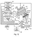
- Fig. 12 is a block diagram illustrating one manner in which an inkjet printer may be operated and calibrated in accordance with the present invention as described above.
- the ink jet printer illustrated in Fig. 12 includes a printer head 20 mounting a line of nozzles 21 each discharging a stream of liquid ink drops towards a substrate 22 for deposition thereon according to a desired pattern to be printed.
- the printer head 20 includes a reservoir of liquid ink and a piezoelectric perturbation device for producing a stream of liquid ink drops originally along the axis of the respective nozzle, but selectively charged by charging plates 23 and deflected by deflecting plates 24 according to the desired pattern to be printed on the substrate.
- the overall operation of the apparatus is controlled by a system controller 25 according to the data inputted via an input device 26.
- the system controller 25 controls the charges applied to the charging plates 23 by means of a charger circuit 27 and a phase shifter circuit 28. Controller 25 also controls the charges to be applied to the deflector plates 24 via a deflector circuit 29.
- controller 25 further controls the printer mechanical drive 30, the printer electrical drive (e.g. the perturbation piezoelectric device) 31, the substrate drive 32, and a display 33.
- Fig. 12 also illustrates the additional components for controlling the operation of the apparatus as described above, and particularly for calibrating it as described with respect to Figs. 7-11 .
- the system is provided with a stroboscopic illumination unit, generally designated 40, incorporating unit 10 in Fig. 7 and unit 10a in Fig. 7a , and with a video imaging unit, generally designated 41, incorporating unit 11 in Fig. 7 and unit 11a in Fig. 7a .
- the illumination unit 40 may be an LED stroboscopic device having the ability to strobe at a frequency equal to the drop generation frequency; and the video imaging unit 41 may include one or more CCD cameras and one or more imaging optics capable of capturing the ink drops "on the fly” either upstream (for drop formation calibration) or downstream (for speed, alignment and phase calibration).
- Video imaging unit 41 displays the ink drops in a display 42, and/or digitally stores them and processes them with a frame grabber of a computer, to enable automatic calibration of the apparatus as described above with respect to Figs. 7-11 .
- the LED stroboscopic device 40 includes a drive, shown at 43, also controlled by the system controller 25.
- Fig. 12 therefore illustrates the inclusion of a computer 44 for making this computation automatically.
- the system controller 25 could include a manual (or automatic) input device 45 for controlling the charger circuit 27 to compensate for drop velocity errors or incorrect drop charging.
- Printing errors resulting from incorrect phasing between the charging pulses applied to the ink drops at the nozzles 21 and the ink drop break-off times, can be corrected by an input 46 to the system controller 25 controlling the phase shifter circuit 28.
- the formation of satellites in the ink drops can be suppressed by an input 47 to the system controller 25 for controlling the piezoelectric perturbation drive 31.
- the perturbation device within the printer head 20 can be controlled so as to produce an optimum shape of the ink drops and with no, or substantially no, satellites.
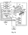
- Fig. 13 illustrates an apparatus, similar to that of Fig. 12 , but provided with a second sensor device, namely a second camera therein designated 50, having a sensor axis 50a at a predetermined angle to the axis 41a of camera 41.
- the outputs of the two cameras 41, 50 are fed to the system controller 25 which processes these outputs, together with the predetermined angle between the axes of the two cameras, to compute any deviation of the stream of ink drops from its respective nozzle axis (a) in the direction parallel to the row of nozzles 21 (X-axis offset), and (b) in the direction perpendicular to the row of nozzles (Y-axis offset).
- System controller 25 corrects the computed X-offset for a particular nozzle by controlling the charger circuit 27 to adjust the charging voltage applied to the charging plates 23 for the respective nozzle.
- System controller 25 corrects the computed Y-axis offset for a particular nozzle by adjusting the timing of the input data from the input device 26 applied by the system controller 25 to the respective nozzle.
- Fig. 13 operates in the same manner as described above with respect to Fig. 12 , and therefore the corresponding parts are identified with the same reference numerals to facilitate understanding.
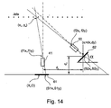
- Fig. 14 illustrates one configuration for measuring the X-axis offset and Y-axis offset from the output of the two cameras 41, 50, where the angle " ⁇ -" is the known predetermined angle between their respective axes. For example, angle " ⁇ -" could be 45°.
- there are geometrical parameters defining the configuration These include the separation (dX, dY) between the imaging device 61 and the imaging device 62, the angle ( ⁇ ) between the imaging device 61 and the imaging device 62, the focal lengths f1 and f2 of the imaging devices 61 and 62 respectively, and the positions (fix, f1 y ) and (f2 x , f2y) of the lenses of the imaging devices 61 and 62 respectively.
- a jet at position (x,y) in the object plane will be imaged at (x i ,0) by the imaging device 61 and at (x1+dX, dY) by the imaging device 62, whereas a jet at position (xn,yn) in the object plane will be imaged at (S1x, S1y) by the imaging device 61 and at (S2x, S2y) by the imaging device 62.
- the object is to measure the geometrical position of the streams of jets with high accuracy by using a stroboscopic arrangement of imaging devices.
- Fig. 14 there are seven geometrical parameters which can not be accurately set or measured, while at the same time their values are required in order to perform the required measurement with the required accuracy.
- the seven parameters are:
- the method employs multiple measurement of each jet, while each measurement is performed at a slightly different position of the cameras carriage relative to the line of jets.
- the movement of the carriage is accurately measured by an encoder.
- the movement of the carriage is adjusted to be predominantly parallel to the row of nozzles (or in an alternative language - to the plane defined by the jets).
- a 1,2 , B 1,2 and C 1,2 represent equations between the geometrical parameters and the measured quantities (x,S1x,S1y,S2x,S2y).
Landscapes
- Particle Formation And Scattering Control In Inkjet Printers (AREA)
- Ink Jet (AREA)
- Ink Jet Recording Methods And Recording Media Thereof (AREA)
- Inks, Pencil-Leads, Or Crayons (AREA)
Claims (17)
- - Procédé pour faire fonctionner un appareil d'impression pour imprimer un motif désiré sur un substrat, comprenant les opérations consistant à :- décharger un courant continu de gouttes d'encre liquide (5) à partir d'une buse (2; 21) le long de l'axe de buse (3) vers le substrat (4) ; et- charger sélectivement (6) lesdites gouttes d'encre liquide par des charges multi-niveaux pour les faire dévier sélectivement de différentes quantités par rapport à l'axe de buse, pour diriger de cette façon une partie des gouttes d'encre liquide vers différents emplacements (9a-9n) sur le substrat pour imprimer ledit motif désiré sur celui-ci, alors que d'autres gouttes d'encre liquide ne devant pas être imprimées sont interceptées par une gouttière (8) avant d'atteindre le substrat (4),caractérisé par le fait que ledit procédé comprend les opérations consistant à :- diviser le courant de gouttes d'encre déchargées de la buse (2 ; 21) en deux courants par des impulsions de chargement de deux niveaux de chargement et de phases appropriées ;- détecter optiquement (10, 11 ; 40, 50) les deux courants de gouttes d'encre pour déterminer des erreurs de vitesse et/ou des erreurs de mise en phase de charge entre les impulsions de chargement respectives et la temporisation de la formation de gouttes physiques dans le courant sortant de la buse (2 ; 21); et- commander (25) les impulsions de chargement et/ou la temporisation de la formation des gouttes pour corriger lesdites erreurs.
- - Procédé selon la revendication 1, caractérisé par le fait que les erreurs de mise en phase de charge sont détectées et sont corrigées (27, 28) par correction du retard temporel entre l'impulsion de chargement respective et la séparation de gouttes physiques dans le courant sortant de la buse (4).
- - Procédé selon la revendication 1, caractérisé par le fait que des erreurs de vitesse sont détectées et sont corrigées (27) par modification des niveaux des charges appliquées aux gouttes d'encre.
- - Procédé selon la revendication 1, caractérisé par le fait que lesdits deux courants de gouttes d'encre sont détectés optiquement à la volée par éclairement de celles-ci par de la lumière stroboscopique (40) à la fréquence de la formation des gouttes.
- - Procédé selon la revendication 1, caractérisé par le fait qu'au moins deux dispositifs détecteurs optiques (41, 50) sont utilisés pour détecter les gouttes d'encre liquide de chacun desdits courants, lesdits dispositifs détecteurs (41, 50) ayant des axes de détecteur à un angle prédéterminé l'un de l'autre ; et
les sorties desdits dispositifs détecteurs (41, 50), comprenant ledit angle prédéterminé de leurs axes de détecteur, sont utilisées pour calculer des déviations selon l'axe des X et selon l'axe des Y du courant respectif de gouttes d'encre à partir de l'axe de buse respectif, respectivement dans la direction parallèle à ladite rangée de buses (2 ; 21), et dans la direction perpendiculaire à ladite rangée de buses (2 ; 21). - - Procédé selon la revendication 5, caractérisé par le fait que chacun desdits détecteurs optiques comprend une caméra (41, 50) ayant une lentille d'imagerie.
- - Procédé selon la revendication 5, caractérisé par le fait que ladite déviation selon l'axe des X calculée pour une buse particulière (2 ; 21) est corrigée (27) par ajustement des tensions de chargement pour la buse respective (2 ; 21).
- - Procédé selon la revendication 5, caractérisé par le fait que ladite déviation selon l'axe des Y calculée pour une buse particulière (2 ; 21) est corrigée par ajustement (28) de la temporisation desdites données d'entrée à la buse respective (2 ; 21).
- - Appareil d'impression pour imprimer un motif désiré sur un substrat, comprenant :- une buse (2 ; 21) pour former et décharger un courant continu de gouttes d'encre liquide (15) le long de l'axe de la buse vers le substrat (4 ; 22) ;- des plaques de chargement (6 ; 23) pour charger sélectivement les gouttes d'encre liquide avec des charges multi-niveaux ;- des plaques déflectrices (7 ; 24) pour dévier sélectivement les gouttes d'encre liquide de différentes quantités par rapport à l'axe de la buse pour diriger de cette façon une partie des gouttes d'encre liquide vers différents emplacements (9a-9n) sur le substrat (4 ; 22) pour imprimer sur celui-ci le motif désiré ;- une gouttière (8) pour intercepter, avant d'atteindre le substrat (4 ; 22) les gouttes d'encre liquide qui ne doivent pas être imprimées ;- un dispositif détecteur (11 ; 41, 50) pour détecter lesdites gouttes d'encre déchargées par ladite buse (2 ; 21) vers le substrat (4 ; 22) ; et- un système de commande (25) pour commander lesdites plaques de chargement (6 ; 23) et lesdites plaques déflectrices (7 ; 24) ;caractérisé par le fait que ledit système de commande (25) est agencé :(a) pour commander lesdites plaques de chargement (6 ; 23) et lesdites plaques déflectrices (7 ; 24) pour diviser le courant de gouttes d'encre déchargées par ladite buse (2 ; 21) en deux courants par des impulsions de chargement de deux niveaux de chargement et de phases appropriées ; et(b) également pour traiter la sortie dudit dispositif détecteur (11; 41, 50) pour déterminer et pour corriger (27, 28, 29) des erreurs de vitesse et/ou des erreurs de mise en phase de charge entre les impulsions de chargement respectives et la temporisation de la formation de gouttes physiques dans le courant sortant de la buse (2 ; 21).
- - Appareil selon la revendication 9, caractérisé par le fait que ledit appareil comprend en outre un dispositif d'éclairement stroboscopique (10 ; 40) pour éclairer le courant de gouttes déchargées à partir de la buse (2 ; 21) à la fréquence de la formation des gouttes ; ledit dispositif détecteur (11 ; 41, 50) comprenant un dispositif d'imagerie vidéo (11 ; 41, 50) pour imager et afficher le courant de gouttes d'encre liquide déchargées de la buse (2 ; 21).
- - Appareil selon la revendication 10, caractérisé par le fait que ledit dispositif d'imagerie vidéo (11 ; 41, 50) comprend une caméra CDD et une lentille d'imagerie.
- - Appareil selon la revendication 10, caractérisé par le fait que ledit dispositif d'éclairement stroboscopique (10 ; 40) est une DEL.
- - Appareil selon la revendication 9, caractérisé par le fait que :- ledit appareil d'impression comprend une pluralité desdites buses (21) pour former et décharger un courant continu de gouttes d'encre liquide à partir de chaque buse (21) le long de l'axe de buse vers le substrat ; ladite pluralité de buses (21) ayant des axes de buse disposés dans au moins une rangée, chacune desdites buses étant commandée sélectivement par des données d'entrée selon le motif désiré devant être imprimé ;- chacune desdites buses (21) comprend lesdites plaques de chargement (23) pour charger sélectivement les gouttes d'encre liquide et plaques déflectrices (24) pour dévier sélectivement les gouttes d'encre liquide ;- ledit appareil comprend au moins deux desdits dispositifs détecteurs (41, 50) pour détecter les gouttes d'encre liquide de chacun desdits courants, lesdits dispositifs détecteurs (41, 50) ayant des axes de détecteur à angle prédéterminé l'un de l'autre ; et- ledit système de commande (25) traite des sorties desdits dispositifs détecteurs (41, 50), calcule les déviations selon l'axe des X et l'axe des Y du courant respectif de gouttes d'encre à partir de l'axe de buse respectif dans la direction parallèle à ladite rangée de buses (21), et dans la direction perpendiculaire à ladite rangée de buses (21), respectivement et corrige le motif imprimé par la buse respective (21) conformément aux déviations calculées.
- - Appareil selon la revendication 13, caractérisé par le fait que lesdits dispositifs détecteurs (41, 50) sont des détecteurs optiques, et lesdits courants de gouttes d'encre sont éclairés par de la lumière stroboscopique (10, 40) à la même fréquence que la formation des gouttes.
- - Appareil d'impression selon la revendication 14, caractérisé par le fait que chacun desdits détecteurs optiques (41, 50) comprend une caméra ayant une lentille d'imagerie.
- - Appareil d'impression selon la revendication 13, caractérisé par le fait que ledit système de commande (25) corrige lesdites déviations selon l'axe des X pour une buse particulière par ajustement des tensions de chargement (27) appliquées à la buse respective (21).
- - Appareil d'impression selon la revendication 13, caractérisé par le fait que ledit système de commande corrige lesdites déviations selon l'axe des X pour une buse particulière (21) par ajustement de la temporisation (28) desdites données d'entrée à la buse respective (21).
Applications Claiming Priority (3)
| Application Number | Priority Date | Filing Date | Title |
|---|---|---|---|
| US28809701P | 2001-05-03 | 2001-05-03 | |
| US288097P | 2001-05-03 | ||
| PCT/IL2002/000346 WO2002090119A2 (fr) | 2001-05-03 | 2002-05-02 | Imprimantes a jet d'encre et procedes |
Publications (3)
| Publication Number | Publication Date |
|---|---|
| EP1390207A2 EP1390207A2 (fr) | 2004-02-25 |
| EP1390207A4 EP1390207A4 (fr) | 2004-08-04 |
| EP1390207B1 true EP1390207B1 (fr) | 2008-02-27 |
Family
ID=23105725
Family Applications (1)
| Application Number | Title | Priority Date | Filing Date |
|---|---|---|---|
| EP02728002A Expired - Lifetime EP1390207B1 (fr) | 2001-05-03 | 2002-05-02 | Imprimantes a jet d'encre et procedes |
Country Status (7)
| Country | Link |
|---|---|
| US (2) | US7104634B2 (fr) |
| EP (1) | EP1390207B1 (fr) |
| AT (1) | ATE387316T1 (fr) |
| AU (1) | AU2002258130A1 (fr) |
| DE (1) | DE60225267D1 (fr) |
| ES (1) | ES2302807T3 (fr) |
| WO (1) | WO2002090119A2 (fr) |
Families Citing this family (41)
| Publication number | Priority date | Publication date | Assignee | Title |
|---|---|---|---|---|
| EP1390207B1 (fr) * | 2001-05-03 | 2008-02-27 | Jemtex Ink Jet Printing Ltd. | Imprimantes a jet d'encre et procedes |
| EP1467868A4 (fr) | 2002-01-02 | 2009-04-01 | Jemtex Ink Jet Printing Ltd | Dispositif d'impression a jet d'encre |
| EP1565316A4 (fr) | 2002-11-25 | 2009-11-18 | Jemtex Ink Jet Printing Ltd | Procede et appareil d'impression par jet d'encre |
| WO2005087495A1 (fr) * | 2004-03-17 | 2005-09-22 | Kodak Graphic Communications Canada Company | Procede et dispositif de regulation de la charge de gouttelettes |
| US20050248605A1 (en) * | 2004-05-10 | 2005-11-10 | Pinard Adam I | Jet printer calibration |
| GB0505874D0 (en) * | 2005-03-22 | 2005-04-27 | Ten Cate Advanced Textiles Bv | Method for providing a localised finish on a textile article |
| EP1875404B1 (fr) * | 2005-04-25 | 2013-06-12 | Ulvac, Inc. | Systeme d'analyse de gouttes |
| ATE463772T1 (de) | 2005-09-15 | 2010-04-15 | Fujifilm Dimatix Inc | Wellenformungsschnittstelle |
| US7360851B1 (en) * | 2006-02-15 | 2008-04-22 | Kla-Tencor Technologies Corporation | Automated pattern recognition of imprint technology |
| JP2007256449A (ja) * | 2006-03-22 | 2007-10-04 | Toshiba Corp | 液滴噴射検査装置、液滴噴射装置及び塗布体の製造方法 |
| US8246138B2 (en) * | 2007-07-06 | 2012-08-21 | Hewlett-Packard Development Company, L.P. | Print emulation of test pattern |
| DE102008019330B4 (de) | 2008-04-16 | 2023-01-26 | Voxeljet Ag | Verfahren und Vorrichtung zum schichtweisen Aufbau von Modellen |
| WO2010011202A1 (fr) * | 2008-07-23 | 2010-01-28 | Hewlett-Packard Development Company, L.P. | Dispositif de détection de la qualité d’orifice d’impression |
| US20120287198A1 (en) * | 2011-05-11 | 2012-11-15 | Fujifilm Dimatix, Inc. | Imaging Jetted Ink |
| CN103917303A (zh) * | 2011-11-07 | 2014-07-09 | 株式会社爱发科 | 喷墨式装置以及液滴测定方法 |
| US8807715B2 (en) | 2012-01-26 | 2014-08-19 | Eastman Kodak Company | Printed drop density reconfiguration |
| US8752924B2 (en) | 2012-01-26 | 2014-06-17 | Eastman Kodak Company | Control element for printed drop density reconfiguration |
| US8764168B2 (en) | 2012-01-26 | 2014-07-01 | Eastman Kodak Company | Printed drop density reconfiguration |
| US8714675B2 (en) | 2012-01-26 | 2014-05-06 | Eastman Kodak Company | Control element for printed drop density reconfiguration |
| US8454134B1 (en) | 2012-01-26 | 2013-06-04 | Eastman Kodak Company | Printed drop density reconfiguration |
| US8714674B2 (en) | 2012-01-26 | 2014-05-06 | Eastman Kodak Company | Control element for printed drop density reconfiguration |
| US8540351B1 (en) | 2012-03-05 | 2013-09-24 | Milliken & Company | Deflection plate for liquid jet printer |
| US9452602B2 (en) | 2012-05-25 | 2016-09-27 | Milliken & Company | Resistor protected deflection plates for liquid jet printer |
| JP6022391B2 (ja) * | 2013-03-28 | 2016-11-09 | 株式会社日立産機システム | インクジェット記録装置 |
| CN105682930B (zh) * | 2013-10-30 | 2018-01-26 | 惠普发展公司,有限责任合伙企业 | 液滴图像传感 |
| US10451482B2 (en) | 2014-02-14 | 2019-10-22 | Palo Alto Research Center Incorporated | Determination of color characteristics of objects using spatially modulated light |
| US9952033B2 (en) | 2014-02-14 | 2018-04-24 | Palo Alto Research Center Incorporated | Spatial modulation of light to determine object length |
| US9207066B2 (en) | 2014-02-14 | 2015-12-08 | Palo Alto Research Center Incorporated | Spatial modulation of light to determine dimensional characteristics of objects in a flow path |
| US9528925B2 (en) | 2014-02-14 | 2016-12-27 | Palo Alto Research Center Incorporated | Spatial modulation of light to determine object position |
| US9415600B2 (en) * | 2014-03-31 | 2016-08-16 | Xerox Corporation | System for detecting inoperative inkjets in three-dimensional object printing using a digital camera and strobe light |
| US9400174B2 (en) | 2014-04-07 | 2016-07-26 | Palo Alto Research Center Incorporated | Monitor for particle injector |
| US9114606B1 (en) * | 2014-04-07 | 2015-08-25 | Palo Alto Research Center Incorporated | Spatial light modulation method for determining droplet motion characteristics |
| JP6657625B2 (ja) * | 2014-09-05 | 2020-03-04 | ソニー株式会社 | 液滴分取装置、液滴分取方法及びプログラム |
| JP6607759B2 (ja) * | 2015-10-08 | 2019-11-20 | 株式会社日立産機システム | 帯電制御型インクジェットプリンタおよびそれを用いた印字方法 |
| JP7045805B2 (ja) * | 2017-06-12 | 2022-04-01 | 株式会社日立産機システム | インクジェット記録装置およびインクジェット記録方法 |
| WO2019125480A1 (fr) | 2017-12-22 | 2019-06-27 | Hewlett-Packard Development Company, L.P. | Réduction d'aérosol à jet d'encre |
| EP3705295B1 (fr) * | 2019-03-06 | 2023-04-19 | Paul Leibinger GmbH & Co. KG Nummerier- und Markierungssysteme | Procédé de fonctionnement d'une imprimante jet d'encre continu à surveillance optique de la qualité d'impression, imprimante à jet d'encre continu à surveillance optique de la qualité d'impression et procédé d'apprentissage d'une imprimante à jet d'encre continu à surveillance optique de la qualité d'impression |
| EP4041444B1 (fr) * | 2019-10-02 | 2024-08-28 | Piotr Jeuté | Procédé et système de contrôle de chute de collisions à la demande |
| WO2021126289A1 (fr) | 2019-12-20 | 2021-06-24 | Hewlett-Packard Development Company, L.P. | Éjection de fluide intégrée et imagerie |
| CN114714766A (zh) * | 2022-04-01 | 2022-07-08 | 北京博示电子科技有限责任公司 | 检测装置及喷墨打印机 |
| CN117734314A (zh) * | 2022-09-13 | 2024-03-22 | 杜文华 | 控制墨滴形态的方法和喷墨打印装置 |
Family Cites Families (17)
| Publication number | Priority date | Publication date | Assignee | Title |
|---|---|---|---|---|
| GB1124163A (en) * | 1964-09-25 | 1968-08-21 | Clevite Corp | Electrically operated character printer |
| US4350986A (en) * | 1975-12-08 | 1982-09-21 | Hitachi, Ltd. | Ink jet printer |
| GB1563856A (en) * | 1976-06-10 | 1980-04-02 | Coulter Electronics | Methods and apparatus for delectively separating small particles suspended in a liquid |
| US4491852A (en) * | 1982-07-02 | 1985-01-01 | Ricoh Company, Ltd. | Ink jet printing apparatus using guard drops |
| GB8514751D0 (en) * | 1985-06-11 | 1985-07-10 | Domino Printing Sciences Plc | Ink jet printing |
| US4829324A (en) * | 1987-12-23 | 1989-05-09 | Xerox Corporation | Large array thermal ink jet printhead |
| GB9001654D0 (en) * | 1990-01-24 | 1990-03-21 | Domino Printing Sciences Plc | Printhead for continuous ink jet printer |
| GB2259276B (en) * | 1991-09-06 | 1995-09-27 | Linx Printing Tech | Ink jet printer |
| JPH07186388A (ja) * | 1993-11-22 | 1995-07-25 | Xerox Corp | 大規模配列インク・ジェット・プリントヘッドおよびその製造方法 |
| AU3186795A (en) * | 1994-09-16 | 1996-03-29 | Videojet Systems International, Inc. | Continuous ink jet printing system for use with hot-melt inks |
| EP0921947A4 (fr) * | 1996-08-07 | 2000-03-08 | Trustees Of Board Of | Configurations de gouttelettes de fluide bidimensionnelles generees au moyen d'une seule buse |
| US5969733A (en) | 1996-10-21 | 1999-10-19 | Jemtex Ink Jet Printing Ltd. | Apparatus and method for multi-jet generation of high viscosity fluid and channel construction particularly useful therein |
| US5988480A (en) * | 1997-12-12 | 1999-11-23 | Micron Technology, Inc. | Continuous mode solder jet apparatus |
| US6224180B1 (en) * | 1997-02-21 | 2001-05-01 | Gerald Pham-Van-Diep | High speed jet soldering system |
| JPH10305420A (ja) * | 1997-03-04 | 1998-11-17 | Ngk Insulators Ltd | 酸化物単結晶からなる母材の加工方法、機能性デバイスの製造方法 |
| US6003980A (en) | 1997-03-28 | 1999-12-21 | Jemtex Ink Jet Printing Ltd. | Continuous ink jet printing apparatus and method including self-testing for printing errors |
| EP1390207B1 (fr) | 2001-05-03 | 2008-02-27 | Jemtex Ink Jet Printing Ltd. | Imprimantes a jet d'encre et procedes |
-
2002
- 2002-05-02 EP EP02728002A patent/EP1390207B1/fr not_active Expired - Lifetime
- 2002-05-02 DE DE60225267T patent/DE60225267D1/de not_active Expired - Lifetime
- 2002-05-02 US US10/475,523 patent/US7104634B2/en not_active Expired - Lifetime
- 2002-05-02 ES ES02728002T patent/ES2302807T3/es not_active Expired - Lifetime
- 2002-05-02 AU AU2002258130A patent/AU2002258130A1/en not_active Abandoned
- 2002-05-02 AT AT02728002T patent/ATE387316T1/de not_active IP Right Cessation
- 2002-05-02 WO PCT/IL2002/000346 patent/WO2002090119A2/fr not_active Ceased
-
2006
- 2006-08-25 US US11/509,658 patent/US7524042B2/en not_active Expired - Lifetime
Also Published As
| Publication number | Publication date |
|---|---|
| ES2302807T3 (es) | 2008-08-01 |
| US20040130585A1 (en) | 2004-07-08 |
| US7104634B2 (en) | 2006-09-12 |
| EP1390207A2 (fr) | 2004-02-25 |
| EP1390207A4 (fr) | 2004-08-04 |
| DE60225267D1 (de) | 2008-04-10 |
| WO2002090119A2 (fr) | 2002-11-14 |
| AU2002258130A1 (en) | 2002-11-18 |
| WO2002090119A3 (fr) | 2003-05-15 |
| ATE387316T1 (de) | 2008-03-15 |
| US7524042B2 (en) | 2009-04-28 |
| US20060284942A1 (en) | 2006-12-21 |
Similar Documents
| Publication | Publication Date | Title |
|---|---|---|
| EP1390207B1 (fr) | Imprimantes a jet d'encre et procedes | |
| US6003980A (en) | Continuous ink jet printing apparatus and method including self-testing for printing errors | |
| EP0121304A2 (fr) | Etalonnage automatique pour dispositif d'éjection de gouttelettes à la demande | |
| EP0113499B1 (fr) | Imprimante à jet d'encre | |
| CN1137818C (zh) | 一种易于制造的打印机及其实施方法 | |
| US7748829B2 (en) | Adjustable drop placement printing method | |
| US4047183A (en) | Method and apparatus for controlling the formation and shape of droplets in an ink jet stream | |
| JP2889887B2 (ja) | インクジェット装置におけるジェットの方向を調整するための電子的方法と装置 | |
| US20010038397A1 (en) | Line scanning type ink jet recording device capable of finely and individually controlling ink ejection from each nozzle | |
| US6858860B2 (en) | Apparatus and method for measuring natural period of liquid | |
| US7249828B2 (en) | Method and apparatus for controlling charging of droplets | |
| US6550886B2 (en) | Ink jet printer capable of adjusting deflection amount in accordance with positional shift of head modules | |
| MX2014003247A (es) | Metodo y aparato para obtener tinta homogenea para dispositivos de inyeccion de tinta. | |
| US20080106564A1 (en) | Method For Reducing Print-Density Variations In Printers, Particularly In Inkjet Printers | |
| US5523778A (en) | Segmented charge tunnel for drop charging in a printhead | |
| EP0744292B1 (fr) | Procédé et appareil de réglage automatique de la tension de commande des buses dans une imprimante à jet d'encre | |
| US6447108B1 (en) | Continuous inkjet printhead control | |
| RU2359235C2 (ru) | Способ контроля процесса формирования капель в печатающей головке электрокаплеструйного маркиратора и устройство для осуществления способа | |
| EP0964785B1 (fr) | Commande de tete d'impression a jet d'encre continu | |
| JP2003011369A (ja) | インクジェット式記録装置、及び、その駆動方法 | |
| EP0968088B1 (fr) | Impression a jet d'encre en continu | |
| JP2005014453A (ja) | インク液滴制御装置及びそれを備えたインクジェット記録装置 | |
| JPH05193139A (ja) | インクジェット印刷機 | |
| JP3620722B2 (ja) | 固有周期計測装置及びその計測方法 | |
| WO1998028151A9 (fr) | Impression a jet d'encre en continu |
Legal Events
| Date | Code | Title | Description |
|---|---|---|---|
| PUAI | Public reference made under article 153(3) epc to a published international application that has entered the european phase |
Free format text: ORIGINAL CODE: 0009012 |
|
| 17P | Request for examination filed |
Effective date: 20031126 |
|
| AK | Designated contracting states |
Kind code of ref document: A2 Designated state(s): AT BE CH CY DE DK ES FI FR GB GR IE IT LI LU MC NL PT SE TR |
|
| AX | Request for extension of the european patent |
Extension state: AL LT LV MK RO SI |
|
| RIC1 | Information provided on ipc code assigned before grant |
Ipc: 7B 41J 2/09 A |
|
| RIC1 | Information provided on ipc code assigned before grant |
Ipc: 7B 41J 2/09 A Ipc: 7B 41J 2/075 B |
|
| A4 | Supplementary search report drawn up and despatched |
Effective date: 20040622 |
|
| 17Q | First examination report despatched |
Effective date: 20050818 |
|
| GRAP | Despatch of communication of intention to grant a patent |
Free format text: ORIGINAL CODE: EPIDOSNIGR1 |
|
| GRAS | Grant fee paid |
Free format text: ORIGINAL CODE: EPIDOSNIGR3 |
|
| GRAA | (expected) grant |
Free format text: ORIGINAL CODE: 0009210 |
|
| AK | Designated contracting states |
Kind code of ref document: B1 Designated state(s): AT BE CH CY DE DK ES FI FR GB GR IE IT LI LU MC NL PT SE TR |
|
| REG | Reference to a national code |
Ref country code: GB Ref legal event code: FG4D |
|
| REG | Reference to a national code |
Ref country code: CH Ref legal event code: EP |
|
| REG | Reference to a national code |
Ref country code: IE Ref legal event code: FG4D |
|
| REF | Corresponds to: |
Ref document number: 60225267 Country of ref document: DE Date of ref document: 20080410 Kind code of ref document: P |
|
| PG25 | Lapsed in a contracting state [announced via postgrant information from national office to epo] |
Ref country code: FI Free format text: LAPSE BECAUSE OF FAILURE TO SUBMIT A TRANSLATION OF THE DESCRIPTION OR TO PAY THE FEE WITHIN THE PRESCRIBED TIME-LIMIT Effective date: 20080227 |
|
| NLV1 | Nl: lapsed or annulled due to failure to fulfill the requirements of art. 29p and 29m of the patents act | ||
| REG | Reference to a national code |
Ref country code: ES Ref legal event code: FG2A Ref document number: 2302807 Country of ref document: ES Kind code of ref document: T3 |
|
| PG25 | Lapsed in a contracting state [announced via postgrant information from national office to epo] |
Ref country code: AT Free format text: LAPSE BECAUSE OF FAILURE TO SUBMIT A TRANSLATION OF THE DESCRIPTION OR TO PAY THE FEE WITHIN THE PRESCRIBED TIME-LIMIT Effective date: 20080227 |
|
| PG25 | Lapsed in a contracting state [announced via postgrant information from national office to epo] |
Ref country code: BE Free format text: LAPSE BECAUSE OF FAILURE TO SUBMIT A TRANSLATION OF THE DESCRIPTION OR TO PAY THE FEE WITHIN THE PRESCRIBED TIME-LIMIT Effective date: 20080227 |
|
| PG25 | Lapsed in a contracting state [announced via postgrant information from national office to epo] |
Ref country code: NL Free format text: LAPSE BECAUSE OF FAILURE TO SUBMIT A TRANSLATION OF THE DESCRIPTION OR TO PAY THE FEE WITHIN THE PRESCRIBED TIME-LIMIT Effective date: 20080227 Ref country code: PT Free format text: LAPSE BECAUSE OF FAILURE TO SUBMIT A TRANSLATION OF THE DESCRIPTION OR TO PAY THE FEE WITHIN THE PRESCRIBED TIME-LIMIT Effective date: 20080721 Ref country code: SE Free format text: LAPSE BECAUSE OF FAILURE TO SUBMIT A TRANSLATION OF THE DESCRIPTION OR TO PAY THE FEE WITHIN THE PRESCRIBED TIME-LIMIT Effective date: 20080527 Ref country code: DK Free format text: LAPSE BECAUSE OF FAILURE TO SUBMIT A TRANSLATION OF THE DESCRIPTION OR TO PAY THE FEE WITHIN THE PRESCRIBED TIME-LIMIT Effective date: 20080227 |
|
| EN | Fr: translation not filed | ||
| PG25 | Lapsed in a contracting state [announced via postgrant information from national office to epo] |
Ref country code: MC Free format text: LAPSE BECAUSE OF NON-PAYMENT OF DUE FEES Effective date: 20080531 |
|
| REG | Reference to a national code |
Ref country code: CH Ref legal event code: PL |
|
| PLBE | No opposition filed within time limit |
Free format text: ORIGINAL CODE: 0009261 |
|
| STAA | Information on the status of an ep patent application or granted ep patent |
Free format text: STATUS: NO OPPOSITION FILED WITHIN TIME LIMIT |
|
| PG25 | Lapsed in a contracting state [announced via postgrant information from national office to epo] |
Ref country code: LI Free format text: LAPSE BECAUSE OF NON-PAYMENT OF DUE FEES Effective date: 20080531 Ref country code: DE Free format text: LAPSE BECAUSE OF FAILURE TO SUBMIT A TRANSLATION OF THE DESCRIPTION OR TO PAY THE FEE WITHIN THE PRESCRIBED TIME-LIMIT Effective date: 20080528 Ref country code: CH Free format text: LAPSE BECAUSE OF NON-PAYMENT OF DUE FEES Effective date: 20080531 |
|
| 26N | No opposition filed |
Effective date: 20081128 |
|
| PG25 | Lapsed in a contracting state [announced via postgrant information from national office to epo] |
Ref country code: IE Free format text: LAPSE BECAUSE OF NON-PAYMENT OF DUE FEES Effective date: 20080502 Ref country code: FR Free format text: LAPSE BECAUSE OF FAILURE TO SUBMIT A TRANSLATION OF THE DESCRIPTION OR TO PAY THE FEE WITHIN THE PRESCRIBED TIME-LIMIT Effective date: 20081219 |
|
| PG25 | Lapsed in a contracting state [announced via postgrant information from national office to epo] |
Ref country code: CY Free format text: LAPSE BECAUSE OF FAILURE TO SUBMIT A TRANSLATION OF THE DESCRIPTION OR TO PAY THE FEE WITHIN THE PRESCRIBED TIME-LIMIT Effective date: 20080227 |
|
| PG25 | Lapsed in a contracting state [announced via postgrant information from national office to epo] |
Ref country code: LU Free format text: LAPSE BECAUSE OF NON-PAYMENT OF DUE FEES Effective date: 20080502 |
|
| PGFP | Annual fee paid to national office [announced via postgrant information from national office to epo] |
Ref country code: ES Payment date: 20100525 Year of fee payment: 9 |
|
| PG25 | Lapsed in a contracting state [announced via postgrant information from national office to epo] |
Ref country code: TR Free format text: LAPSE BECAUSE OF FAILURE TO SUBMIT A TRANSLATION OF THE DESCRIPTION OR TO PAY THE FEE WITHIN THE PRESCRIBED TIME-LIMIT Effective date: 20080227 |
|
| PGFP | Annual fee paid to national office [announced via postgrant information from national office to epo] |
Ref country code: IT Payment date: 20100521 Year of fee payment: 9 |
|
| PG25 | Lapsed in a contracting state [announced via postgrant information from national office to epo] |
Ref country code: GR Free format text: LAPSE BECAUSE OF FAILURE TO SUBMIT A TRANSLATION OF THE DESCRIPTION OR TO PAY THE FEE WITHIN THE PRESCRIBED TIME-LIMIT Effective date: 20080528 |
|
| PGFP | Annual fee paid to national office [announced via postgrant information from national office to epo] |
Ref country code: GB Payment date: 20100519 Year of fee payment: 9 |
|
| GBPC | Gb: european patent ceased through non-payment of renewal fee |
Effective date: 20110502 |
|
| PG25 | Lapsed in a contracting state [announced via postgrant information from national office to epo] |
Ref country code: IT Free format text: LAPSE BECAUSE OF NON-PAYMENT OF DUE FEES Effective date: 20110502 |
|
| PG25 | Lapsed in a contracting state [announced via postgrant information from national office to epo] |
Ref country code: GB Free format text: LAPSE BECAUSE OF NON-PAYMENT OF DUE FEES Effective date: 20110502 |
|
| REG | Reference to a national code |
Ref country code: ES Ref legal event code: FD2A Effective date: 20120717 |
|
| PG25 | Lapsed in a contracting state [announced via postgrant information from national office to epo] |
Ref country code: ES Free format text: LAPSE BECAUSE OF NON-PAYMENT OF DUE FEES Effective date: 20110503 |