EP1396366B1 - Motoneige - Google Patents
Motoneige Download PDFInfo
- Publication number
- EP1396366B1 EP1396366B1 EP03019297A EP03019297A EP1396366B1 EP 1396366 B1 EP1396366 B1 EP 1396366B1 EP 03019297 A EP03019297 A EP 03019297A EP 03019297 A EP03019297 A EP 03019297A EP 1396366 B1 EP1396366 B1 EP 1396366B1
- Authority
- EP
- European Patent Office
- Prior art keywords
- cylinder
- snowmobile
- crankshaft
- internal combustion
- combustion engine
- Prior art date
- Legal status (The legal status is an assumption and is not a legal conclusion. Google has not performed a legal analysis and makes no representation as to the accuracy of the status listed.)
- Expired - Lifetime
Links
- 238000002485 combustion reaction Methods 0.000 claims description 70
- XLYOFNOQVPJJNP-UHFFFAOYSA-N water Substances O XLYOFNOQVPJJNP-UHFFFAOYSA-N 0.000 claims description 31
- 239000000498 cooling water Substances 0.000 claims description 8
- 239000003921 oil Substances 0.000 description 26
- 230000005484 gravity Effects 0.000 description 15
- 239000010687 lubricating oil Substances 0.000 description 15
- 238000001816 cooling Methods 0.000 description 8
- 230000005540 biological transmission Effects 0.000 description 6
- 230000009286 beneficial effect Effects 0.000 description 5
- 238000001125 extrusion Methods 0.000 description 4
- 239000000446 fuel Substances 0.000 description 4
- 238000010586 diagram Methods 0.000 description 3
- 230000001050 lubricating effect Effects 0.000 description 3
- 230000001105 regulatory effect Effects 0.000 description 3
- 230000003139 buffering effect Effects 0.000 description 2
- 230000008878 coupling Effects 0.000 description 2
- 238000010168 coupling process Methods 0.000 description 2
- 238000005859 coupling reaction Methods 0.000 description 2
- 238000005461 lubrication Methods 0.000 description 2
- 238000012423 maintenance Methods 0.000 description 2
- 230000002000 scavenging effect Effects 0.000 description 2
- 230000003247 decreasing effect Effects 0.000 description 1
- 230000000694 effects Effects 0.000 description 1
- 230000005611 electricity Effects 0.000 description 1
- 238000001914 filtration Methods 0.000 description 1
- 239000000463 material Substances 0.000 description 1
- 230000010355 oscillation Effects 0.000 description 1
- 239000000725 suspension Substances 0.000 description 1
Images




Classifications
-
- B—PERFORMING OPERATIONS; TRANSPORTING
- B60—VEHICLES IN GENERAL
- B60K—ARRANGEMENT OR MOUNTING OF PROPULSION UNITS OR OF TRANSMISSIONS IN VEHICLES; ARRANGEMENT OR MOUNTING OF PLURAL DIVERSE PRIME-MOVERS IN VEHICLES; AUXILIARY DRIVES FOR VEHICLES; INSTRUMENTATION OR DASHBOARDS FOR VEHICLES; ARRANGEMENTS IN CONNECTION WITH COOLING, AIR INTAKE, GAS EXHAUST OR FUEL SUPPLY OF PROPULSION UNITS IN VEHICLES
- B60K5/00—Arrangement or mounting of internal-combustion or jet-propulsion units
- B60K5/02—Arrangement or mounting of internal-combustion or jet-propulsion units with the engine main axis, e.g. crankshaft axis, substantially in or parallel to the longitudinal centre line of the vehicle
-
- B—PERFORMING OPERATIONS; TRANSPORTING
- B62—LAND VEHICLES FOR TRAVELLING OTHERWISE THAN ON RAILS
- B62M—RIDER PROPULSION OF WHEELED VEHICLES OR SLEDGES; POWERED PROPULSION OF SLEDGES OR SINGLE-TRACK CYCLES; TRANSMISSIONS SPECIALLY ADAPTED FOR SUCH VEHICLES
- B62M27/00—Propulsion devices for sledges or the like
- B62M27/02—Propulsion devices for sledges or the like power driven
-
- B—PERFORMING OPERATIONS; TRANSPORTING
- B62—LAND VEHICLES FOR TRAVELLING OTHERWISE THAN ON RAILS
- B62M—RIDER PROPULSION OF WHEELED VEHICLES OR SLEDGES; POWERED PROPULSION OF SLEDGES OR SINGLE-TRACK CYCLES; TRANSMISSIONS SPECIALLY ADAPTED FOR SUCH VEHICLES
- B62M27/00—Propulsion devices for sledges or the like
- B62M27/02—Propulsion devices for sledges or the like power driven
- B62M2027/023—Snow mobiles characterised by engine mounting arrangements
Definitions
- the present invention relates to a snowmobile comprising a vehicle body holding a driving means placeable on a running surface and an internal combustion engine interlocked with the driving means, wherein the internal combustion engine is provided with a crankcase for supporting a crankshaft, and a cylinder extended from this crankcase.
- Such a snowmobile is for example disclosed in JP-A-5-229474.
- the snowmobile disclosed therein includes: driving means placed on a running surface while being held by a rear part of a vehicle body for making, by rotating, the vehicle body capable of driving; an orientation ski placed on the running surface while being supported by a front part of the vehicle body to be orientable for making, by orientating, the vehicle body orientable; and a for-driving four-cycle internal combustion engine held by a middle part of the fore-and-aft length of the vehicle body and interlocked with the driving means.
- this internal combustion engine is provided with a crankcase held by the vehicle body for supporting a crankshaft, and a cylinder extruding from this crankcase.
- the driving means By driving the internal combustion engine for transferring its driving force to the driving means, the driving means is accordingly driven and thereby, the snowmobile becomes able to run on the running surface.
- the running surface on which a snowmobile runs is generally quite uneven.
- the driving means for running tends to slip against the running surface when the snowmobile is running
- the resulting running fails to satisfactorily respond to the driving force coming from the internal combustion engine. This reduces the ride comfort of the snowmobile and thus is not preferable.
- the internal combustion engine includes: an air cleaner large in outer dimensions as a component of structuring an intake device therein; a water pump structuring a cooling device for cooling the internal combustion engine by cooling water; and a battery.
- an air cleaner large in outer dimensions as a component of structuring an intake device therein
- a water pump structuring for cooling the internal combustion engine by cooling water
- a battery for cooling the internal combustion engine by cooling water
- the issue here is that, in the vehicle body having only a limited narrow redundant space, it is not easy to place, in a compact manner, the above-described components of the internal combustion engine such as the balancer shaft, air cleaner, water pump, and battery without impairing their each function.
- US-A1-2002000340 discloses a snow mobile according to the preamble of claim 1.
- the current invention solves this problem by providing a balancer shaft supported by the crankcase directly above the crankshaft and interlocked with the crankshaft by a gear type interlocking means
- the center of gravity is lower in the internal combustion engine.
- the center of gravity of the snowmobile becomes lower, and thereby, the stability of the snowmobile is improved at the time of running.
- the cylinder is made extruded upward from the crankcase towards the rear, the center of the gravity of the internal combustion engine is brought closer to the side of the driving means locating therebehind. Thereby, the snowmobile held by the driving means is increased in weight to a greater degree.
- the snowmobile can suitably run according to the driving force output from the internal combustion engine, and the ride comfort of the snowmobile can be accordingly improved.
- a balancer shaft supported by the crankcase and interlocked with the crankshaft is provided directly above the crankshaft.
- the cylinder is extruding upward from the crankcase towards the rear.
- the balancer shaft Utilizing the redundant space directly above the crankshaft, the balancer shaft is fitly placed. Placing the balancer shaft directly above the crankshaft in this way eliminates the need for lifting upward the heavy crankshaft, and the piston and the interlock rod connected thereto for the purpose of securing the space to be occupied by the balancer shaft.
- the center of the gravity remains low in the snowmobile, improving the stability of the snowmobile when running.
- the internal combustion engine includes an air cleaner to be interlocked with the cylinder, the air cleaner is provided toward above or front of a front surface of the cylinder.
- the carburetor and the air cleaner is provided above and towards the front of the front surface of the cylinder.
- the air cleaner is located above and towards the front of the cylinder.
- the running wind blown when the snowmobile runs is sucked in to the cylinder through the air cleaner. This is considered beneficial in terms of engine capability.
- a reference numeral 1 in the drawings is a saddle-provided conveyance, as an example thereof, a snowmobile is shown. Also, an arrow Fr in the drawings indicates a forward direction of the snowmobile 1.
- the snowmobile 1 includes: driving means 4 placed on a running surface 3 being a snow plane while being held by the rear part of the vehicle body 2 for making, by rotating, the vehicle body 2 capable of running; a right-and-left pair of orientation skis 5 and 5 orientably supported by the front part of the vehicle body 2 and placed on the running surface 3 for making, by orientating, the vehicle body 2 orientable; a for-driving internal combustion engine 6 placed inside of a part in the middle of the fore-and-aft length of the vehicle body 2 and held thereby; an automatic various-speed transmission 7 to be interlocked with the internal combustion engine 6; and gear-type driveline equipment 8 for interlock with the driving means 4 while being interlocked with the transmission 7. That is, the driving means 4 and the internal combustion engine 6 are interlocked with each other via the transmission 7 and the driveline equipment 8.
- an orientation handle 9 to be interlocked with each of the orientation skis 5 is supported.
- the vehicle body 2 includes: a vehicle main body 13 having a vehicle body frame being a framework thereof; a sheet 14 held by the vehicle main body 13 at the rear of the orientation handle 9 to allow a rider to seat thereon; a foot rest 15 provided to extrude from respective right and left sides of the vehicle main body 13 to allow the rider seated on the seat 14 to place his or her feet thereon; and a shield 16 provided and extruded so as to direct upward from the vehicle main body 13 in proximity to the front of the orientation handle 9.
- the driving means 4 includes driving and follower rotation wheels 18 and 19, both of which are supported by the vehicle body 2 to be rotatable via a suspension system.
- a truck belt 20 is also included to be wound around these rotation wheels 18 and 19. The lower rear surface of the truck belt 20 extends almost horizontally to abut to the running plane 3.
- the internal combustion engine 6 includes: an internal combustion engine body 22 being a four-cycle multi-cylinder (three-cylinder) engine to be held by the vehicle body 2; an intake device 25 for providing atmospheric air 23 and fuel 24 to the internal combustion engine body 22; and an exhaust device 27 for exhausting a combustion product 26 from the internal combustion engine body 22 onto the atmospheric side.
- an internal combustion engine body 22 being a four-cycle multi-cylinder (three-cylinder) engine to be held by the vehicle body 2
- an intake device 25 for providing atmospheric air 23 and fuel 24 to the internal combustion engine body 22
- an exhaust device 27 for exhausting a combustion product 26 from the internal combustion engine body 22 onto the atmospheric side.
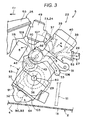
- the internal combustion engine body 22 includes: a crankcase 30 held by the vehicle body 2 for supporting a crankshaft 29; a cylinder 31 extruding upward from the crankcase 30 towards the rear; an oil pan 32 provided in such a manner as to cover the lower surface side of the crankcase 30 from below; a piston 34 to be pushed into a cylinder hole 33 of the cylinder 31 to freely slide; and an interlock rod 35 for interlocking the crankshaft 29 and the piston 34 with each other.
- a center axis 36 is extending straight in a direction across the vehicle 2 (lateral direction).
- the internal combustion engine 6 includes: intake and exhaust paths 37 and 38 both provided at the extruding tip part of the cylinder 31 for making the cylinder hole 33 through inside and outside thereof; and intake and exhaust valves 39 and 40 for opening and closing the intake and exhaust paths 37 and 38; a move-valve mechanism (not shown) for opening and closing the intake and exhaust valves 39 and 40 as appropriate responding to the movement of the crankshaft 29; and a spark plug 41 whose discharge section is facing a combustion chamber provided at the upper end of the cylinder hole 33.
- the internal combustion engine 6 includes: a balancer shaft 42 placed directly above the crankshaft 29 (in proximity of the upper part thereof) and extending horizontally to the crankshaft 29; gear-type interlock means 43 for interlocking the balancer shaft 42 with the crankshaft 29; and a startup device 44 for enabling the internal combustion engine 6 to start up through interlock with the crankshaft 29.
- the startup device 44 includes a startup motor 45 to be held by the cylinder 31, and gear-type interlock means 46 for interlocking the startup motor 45 with the crankshaft 29.
- the intake device 25 includes: a carburetor 49 coupled to the front surface side of the cylinder 31 to be able to supply the atmospheric air 23 and the fuel 24 to the cylinder hole 33 via the intake path 37; and an air cleaner 50 for filtering the atmospheric air 23 for supply to the carburetor 49.
- the carburetor 49 and the rear part at least partially structuring the air cleaner 50 are placed above the front surface of the cylinder 31 and towards the front of the upper front surface of the cylinder 31, and the air cleaner 50 is placed above front of the balancer shaft 42.
- the exhaust device 27 includes an exhaust pipe 53 extending from the cylinder 31 of the internal combustion engine 6 towards the rear, and a muffler 54 to be coupled to the extending tip part of the exhaust pipe 53.
- the exhaust pipe 53 includes: a plurality of (three) exhaust pipe members 55 structuring the front part of the exhaust pipe 53 and all extending from each of the cylinders of the internal combustion engine 6 towards the rear; a single assembly pipe 56 structuring a middle part of the fore-and-aft length of the exhaust pipe 53 to assemble the extruding tip parts of the exhaust pipe members 55; and a plurality of (two) other exhaust pipe members 57 and 57 structuring the rear part of the exhaust pipe 53 to draw the muffler 54 through the assembly pipe 56.
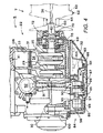
- the transmission 7 includes: an input shaft 60 placed outside of one free end of the crankshaft 29 and on the center axis 36 sharing with the crankshaft 29 to be interlocked with the crankshaft 29; an output shaft 61 interlocked with the driving means 4 via the driveline equipment 8 for outputting a driving force to the driving means 4; and a belt-winding-type interlock means 62 for interlocking the input shaft 60 with the output shaft 62.
- This interlock means 62 includes: a driving pully 63 held by the input shaft 60 for rotating together therewith; a follower pully 64 held by the output shaft 61 for rotating together therewith; and a V belt 65 to be wound around the driving pully 63 and the follower pully 64.
- the deceleration ratio is automatically reduced.
- the input shaft 60 is interlocked in the following manner. That is, one end of the input shaft 60 is held by the crankcase 30 in a cantilever manner by a right-and-left pair of bearings 69 and 70 to be rotatable about the center axis 36. As to the other end of the input shaft 60, the driving pully 63 is held thereby, and a base which is one end of the input shaft 60 is interlocked with one end of the crankshaft 29 via an damper 72.
- the damper 72 includes: a driving-side rotation body 73 held by the crankshaft 29 for rotation together therewith; a follower-side rotation body 74 formed on the base of the input shaft 60; and a rubber-made buffer member 75 provided between the driving-side rotation body 73 and the follower-side rotation body 74 for transferring the driving force therebetween while buffering the same.
- the driving-side rotation body 73 includes a cylinder-shaped boss section 77 held by one end of the crankshaft 29 through spline engagement, and a plurality of extrusion bodies 78 extruding, from center to edge, outward in the radius direction from the boss section 77.
- the follower-side rotation body 74 is formed on the base of the input shaft and a box-shaped so as to cover the driving-side rotation body 73 and the buffer member 75 in their entirety from outside; and includes a casing 79 with its both ends held by the crankcase 30 with the respective bearings 69, 70 another extrusion body 80 provided inside of the casing 79 to be pushed into between the extrusion bodies 78 in a circumferential direction about the center axis 36. Between two extrusion bodies 78 and 80 next to each other in the circumferential direction, the buffer member 75 is provided.
- a lubricating device 84 is provided for providing the internal combustion engine 6 with lubricity using lubricating oil 83.
- the lubricating device 84 includes an oil pan 32 for storing the lubricating oil 83 therein, and a regulatory wall 87 provided between one-side chamber 85 and an another-side chamber 86 locating inside of the oil pan 32 in the lateral direction of the vehicle body 2. This regulatory wall 87 is locating almost in the middle of the vehicle body 2 in the lateral direction, and regulates the flow of lubricating oil 83 between the chambers 85 and 86.
- the lubricating device 84 includes: a right-and-left pair of oil pumps 90 and 90 being scavenging pumps for sucking out the lubricating oil 83 in the oil pan 32; an oil path 91 formed in the cylinder 31 and feeding the lubricating oil 83 sucked out by each of the oil pumps 90 to a lubricating oil tank (not shown) for storage therein; an oil cooler 92 attached to the front surface of the cylinder 31 and cooling the lubricating oil 83 suctioned by each of the oil pumps 90 through the oil path 91; and a supply oil pump 93 for supplying the lubricating oil 83 stored in the lubricating oil tank to every to-be-lubricated section in the internal combustion engine 6.
- the oil pump 90 is provided, respectively, to the one-side chamber 85 and the another-side chamber 86, that is, provided a right-and-left pair thereof as described above.
- the oil pumps 90 and 93 each include: a pump casing 97 accommodated inside of the one-side chamber 85, which is one of the chambers 85 and 86, to structure the hull thereof, and coupled detachably to the lower surface of the crankcase 30 by a coupling member; a pump shaft 98 supported by each of the pump casings 97 to be rotatable about the center axis extending in the lateral direction of the vehicle body 2; and a rotor 99 accommodated in each of the pump casings 97 for rotating together with the corresponding pump shaft 98.
- the pump casing 97 and the corresponding oil pump 90 are formed in a piece.
- a suction inlet 101 for suctioning the lubricating oil 83 into the pump casing 97 of each of the oil pumps 90 is provided two as a right-and-left pair. These suction inlets 101 are closed at the bottom of the one-side chamber 85 and the another-side chamber 86.
- the pump shafts 98 are formed in a piece on the same axis. The pump shafts 98 are interlocked with the crankshaft 29 by chain-wound-type interlock means 100, that is, the oil pumps 90 and 93 can be driven together with the internal combustion engine 6.
- the lubricating oil 83 inside of the oil pun 32 is sucked out and forwarded to the lubricating oil tank.
- the oil pump 93 being a supply pump
- the lubricating oil 83 in the lubricating oil tank is supplied to every to-be-lubricated section in the internal combustion engine 6 for lubrication.
- the lubricating oil 83 after used for lubrication is returned back to the one-side chamber 85 and the another-side chamber 86 in the oil pan 32 by natural flow thereof.
- the oil pan 32 is detachably coupled by the coupling member 103. Removing the oil pan 32 from the lower surface of the crankcase 30 will make the oil pumps 90 and 93 and the lower surface of the interlock means 100 extrude downward from the lower surface of the crankcase 30. This allows attach/detach operation of the interlock means 100 to/from the pump shaft 98, and maintenance and check operations with respect to the oil pumps 90 and 93 and the interlock member 100.
- a cooler device 107 is provided for cooling the internal combustion engine 6 with cooling water 106.
- This cooling device 107 includes: a water jacket 108 formed to the cylinder 31 and the oil cooler 92; a water pump 109 provided above the crankshaft 29 to be held by the cylinder 31 for supplying the cooling water 106 to the water jacket 108; a gear-type interlock means 110 for interlocking the rotor of the water pump 109 with the balancer shaft 42; and a heat exchanger 111 provided in proximity of the rear part of the crankcase 30 for cooling the cooling water 106 which has been supplied to the water jacket 108 to cool therearound.
- the water pump 109 cooperatively move via the balancer shaft 42 and the interlock means 110 to cool every section of the internal combustion engine 6.
- a battery 115 is provided for supplying electricity to the spark plug 41 of the internal combustion engine 6, the startup motor 45 of the startup device 44, an engine control device (not shown), and the like.
- the rear parts at least partially structuring the air cleaner 50 and the battery 115, respectively, are provided above the front surface of the cylinder 31.
- the battery 115 is placed in a space towards the front of the front surface of the cylinder 31, towards the front of the balancer shaft 42, and below the air cleaner 50. Further, the air cleaner 50 and the battery 115 are placed almost in the middle of the vehicle body 2 in the lateral direction to be held thereby.
- the internal combustion engine 6 is started by cranking the crankshaft 29 using the startup motor 45 of the startup device 44, with respect to the cylinder 31, the air 23 is sucked in via the air cleaner 50, the carburetor 49, and the intake path 37 in the intake device 25 in this order. Also, the fuel 24 supplied from the carburetor 49 is sucked in, and the mixed gas of the air 23 and the fuel 24 goes to the cylinder hole 33 in the cylinder 31 to be ignited for combustion by the spark plug 41. Then, the gas as a result of combustion is exhausted, as emission 26, to outside of the internal combustion engine 6 via the exhaust path 38, the exhaust pipe 53 of the exhaust device 27, and the muffler 54 in this order. Thereafter, the internal combustion engine 6 continues its operation. The driving force of the internal combustion engine 6 is transferred to the driving rotation wheel 18 of the driving means 4 via the transmission 7 and the driveline equipment 8 in this order. In response thereto, the truck belt 20 is rotated, thereby allowing the snowmobile 1 to run.
- the cylinder 31 is made extruded upward from the crankcase 30 towards the rear.
- the center of gravity of the snowmobile 1 becomes lower, and thereby, the stability of the snowmobile 1 is improved at the time of running.
- the cylinder 31 is made extruded upward from the crankcase 30 towards the rear. Therefore, the center of the gravity of the internal combustion engine 6 is brought closer to the side of the driving means 4 locating therebehind. Thereby, the snowmobile 1 held by the driving means 4 is increased in weight to a greater degree.
- the snowmobile 1 can suitably run according to the driving force output from the internal combustion engine 6, and the ride comfort of the snowmobile 1 can be accordingly improved.
- the balancer shaft 42 is provided directly above the crankshaft 29.
- the cylinder 31 is extruding upward from the crankcase 30 towards the rear.
- the balancer shaft 42 Utilizing the redundant space directly above the crankshaft 29, the balancer shaft 42 is fitly placed. Placing the balancer shaft 42 directly above the crankshaft 29 in this way eliminates the need for lifting upward the heavy crankshaft 29, and the piston 34 and the interlock rod 35 connected thereto for the purpose of securing the space to be occupied by the balancer shaft 42.
- the carburetor 49 and the air cleaner 50 are provided above and towards the front of the front surface of the cylinder 31.
- the air cleaner 50 is located above and towards the front of the cylinder 31.
- the running wind blown when the snowmobile 1 runs is sucked in to the cylinder 31 through the air cleaner 50. This is considered beneficial in terms of engine capability.
- the input shaft 60 of the transmission 7 is not held by the free end extruding from the crankshaft 29 but is held in a cantilever manner directly by the crankcase 30.
- crankcase 30 is the one retaining stronger strength and stiffness than the free end of the crankcase 29. Accordingly, the hold strength of the input shaft 60 with respect to the internal combustion engine 6 can be improved more without increasing the weight.
- crankshaft 29 is interlocked with the base of the input shaft 60 via the damper 72.
- the damper 72 includes: the driving-side rotation body 73 rotating together with the crankshaft 29; the follower-side rotation body 74 formed on the base of the input shaft 60; and the buffer member 75 provided between the driving-side rotation body 73 and the follower-side rotation body 74 for transferring the driving force therebetween while buffering the same.
- the follower-side rotation body 74 is box-shaped so as to cover the driving-side rotation body 73 and the buffer member 75 from outside.
- both ends of the follower-side rotation body 74 are held by the crankcase 30.
- the internal combustion engine 6 includes the water pump 109 for supplying the cool water 106 to the water jacket 108 of the cylinder 31 through interlock with the balancer shaft 42, and the water pump 109 is placed above the crankshaft 29.
- the cylinder 31 is extruding upward from the crankcase 30 towards the rear.
- the water pump 109 Utilizing the redundant space above the crankshaft 29, the water pump 109 is fitly placed. Placing the water pump 109 above the crankshaft 29 in the way eliminates the need for lifting upward the heavy crankshaft 29, and the piston 34 and the interlock rod 35 connected thereto for the purpose of securing the space to be occupied by the water pump 109.
- the center of the gravity remains low in the snowmobile 1, improving the stability of the snowmobile 1 when running.
- the water pump 109 and a water hose for leading the cooling water 106 discharged from the water pump 109 to a predetermined position of the cylinder 31, for example, are provided on one side of the internal combustion engine 6 in the lateral direction of the vehicle body 2.
- the rear parts at least partially structuring the air cleaner 50 and the battery 115, respectively, are provided above the front surface of the cylinder 31. Also, the battery 115 is placed towards the front of the front surface of the cylinder 31, and below the air cleaner 50.
- the redundant space locating above and towards the front of the front surface of the cylinder 31, and below the air cleaner 50 large in outer dimensions is utilized for the placement of the battery 115. This allows the compact placement of the cylinder 31, the air cleaner 50, and the battery 115.
- the battery 115 is located towards the front of the cylinder 31.
- the running wind blown when the snowmobile 1 runs can reach more directly the battery 115 without being blocked by the cylinder 31, thereby effectively cooling the battery 115.
- the battery 115 is prevented from being high in temperature. This is considered beneficial to keep the performance of the battery 115.
- the above description is based on the shown example.
- the regulatory wall 87 may be plurally provided, and the oil pump 90 may be singularly provided.
- a snowmobile comprising: driving means placed on a running surface while being held by a rear part of a vehicle body for making, by rotating, the vehicle body capable of running; an orientation ski placed on the running surface while being orientably supported by a front part of the vehicle body for making, by orienting, the vehicle body orientable; and a for-driving four-cycle internal combustion engine held by a middle part of the fore-and-aft length of the vehicle body and interlocked with the driving means, and the internal combustion engine being provided with a crankcase held by the vehicle body for supporting a crankshaft, a cylinder extruding from this crank case, and a balancer shaft supported by the crankcase and interlocked with the crankshaft, the cylinder is extruded upward from the crankcase towards the rear.
- the center of gravity is lower in the internal combustion engine.
- the center of gravity of the snowmobile becomes lower, and thereby, the stability of the snowmobile is improved when running.
- the cylinder is made extruded upward from the crankcase towards the rear. Therefore, the center of the gravity is brought closer to the side of the driving means locating behind the internal combustion engine. Thereby, the snowmobile held by the driving means is increased in weight to a greater degree.
- the snowmobile can suitably run according to the driving force output from the internal combustion engine, and the ride comfort of the snowmobile can be accordingly improved.
- the balancer shaft is provided directly above the crankshaft.
- the cylinder is made extruded upward from the crankcase towards the rear.
- the balancer shaft is fitly placed. Placing the balancer shaft directly above the crankshaft in this way eliminates the need to lift upward the heavy crankshaft, and the piston and the interlock rod connected thereto for the purpose of securing the space to be occupied by the balancer shaft.
- the center of the gravity remains low in the snowmobile, improving the stability of the snowmobile 1 when running.
- the air cleaner is placed above and towards the front of the front surface of the cylinder.
- the air cleaner is located above and towards the front of the cylinder.
- the running wind blown when the snowmobile runs is sucked in to the cylinder through the air cleaner. This is considered beneficial in terms of engine performance.
- the internal combustion engine includes a water pump interlocked with the balancer shaft for supplying cooling water to a water jacket of the cylinder, and the water pump is placed above the crankshaft.
- the cylinder is made extruded upward from the crankcase towards the rear.
- the water pump is fitly placed. Placing the water pump above the crankshaft in this way eliminates the need to lift upward the heavy crankshaft, and the piston and the interlock rod connected thereto for the purpose of securing the space to be occupied by the water pump.
- a battery is placed above the cylinder, and below of the air cleaner.
- the battery is located towards the front of the cylinder.
- the running wind blown when the snowmobile runs can reach more directly the battery without being blocked by the cylinder, thereby effectively cooling the battery.
- a snowmobile 1 includes: driving means 4 held by the rear part of a vehicle body 2; an orientation ski 5 supported by the front part of the vehicle body 2; and a for-driving four-cycle internal combustion engine 6 held by a middle section of the fore-and-aft length of the vehicle body 2.
- the internal combustion engine 6 is provided with a crankcase 30 held by the vehicle body for supporting a crankshaft 29, a cylinder 31 extruding from this crankcase 30, and a balancer shaft 42 supported by the crankcase 30 and interlocked with the crankshaft 29.
- the cylinder 31 is extruded upward from the crankcase 30 toward the rear.
- the balancer shaft 42 is provided directly above the crankshaft 29.
Landscapes
- Engineering & Computer Science (AREA)
- Chemical & Material Sciences (AREA)
- Combustion & Propulsion (AREA)
- Transportation (AREA)
- Mechanical Engineering (AREA)
- Cylinder Crankcases Of Internal Combustion Engines (AREA)
- Lubrication Details And Ventilation Of Internal Combustion Engines (AREA)
Claims (8)
- Motoneige (1) comprenant un corps de véhicule (2) supportant des moyens d'entraînement (4) pouvant être placés sur une surface d'avancement (3) et un moteur à combustion interne (6) en engagement avec les moyens d'entraînement (4), dans laquelle le moteur à combustion interne (6) comporte un carter moteur (30) destiné à supporter un vilebrequin (29) et un cylindre (31) qui s'étend à partir de ce carter moteur (30) en inclinaison vers l'arrière par rapport à une direction d'entraînement de la motoneige,
caractérisée en ce que :un arbre d'équilibrage (42) est supporté par le carter moteur (30) directement au-dessus du vilebrequin (29) et en engagement avec le vilebrequin (29) grâce à des moyens d'engagement de type à engrenage (43). - Motoneige selon la revendication 1, caractérisée en ce qu'une pompe à eau (109) destinée à fournir de l'eau de refroidissement (106) à une chemise à eau (108) dudit cylindre (31) est disposée au-dessus dudit vilebrequin (29).
- Motoneige selon la revendication 2, caractérisée en ce que la pompe à eau (109) est en engagement avec ledit arbre d'équilibrage (42) par l'intermédiaire de moyens d'engagement de type à engrenage (110) de telle sorte que la pompe à eau (109) se déplace en coopération avec l'arbre d'équilibrage (42).
- Motoneige selon au moins l'une des revendications 1 à 3, caractérisée en ce que le moteur à combustion interne (6) comprend un filtre à air (50) qui est en engagement avec ledit cylindre (31), dans laquelle ledit filtre à air (50) est disposé vers le dessus, ou à l'avant d'une surface avant dudit cylindre (31).
- Motoneige selon au moins l'une des revendications 1 à 4, caractérisée en ce qu'un dispositif de mise en marche (44) est fourni afin de permettre la mise en marche du moteur (6) malgré un engagement du vilebrequin (29) par des moyens d'engagement de type à engrenage (46).
- Motoneige selon au moins l'une des revendications 1 à 5, caractérisée en ce qu'une batterie (115) est disposée vers l'avant de la surface avant dudit cylindre (31) et en dessous du filtre à air (50).
- Motoneige selon au moins l'une des revendications 1 à 6, caractérisée en ce que les moyens d'entraînement (4) sont supportés sur une partie arrière du corps de véhicule (2), au moins un ski d'orientation (5) est supporté sur une partie avant du corps de véhicule (2), et le moteur (6) est supporté dans une partie intermédiaire de la longueur longitudinale du corps de véhicule (2).
- Motoneige selon au moins l'une des revendications 1 à 7, caractérisée en ce qu'un échangeur de chaleur (111) est disposé à proximité de la partie arrière du carter moteur (3).
Applications Claiming Priority (2)
| Application Number | Priority Date | Filing Date | Title |
|---|---|---|---|
| JP2002246408 | 2002-08-27 | ||
| JP2002246408A JP2004084552A (ja) | 2002-08-27 | 2002-08-27 | スノーモービルにおける構成部品配設構造 |
Publications (2)
| Publication Number | Publication Date |
|---|---|
| EP1396366A1 EP1396366A1 (fr) | 2004-03-10 |
| EP1396366B1 true EP1396366B1 (fr) | 2006-10-25 |
Family
ID=31712237
Family Applications (1)
| Application Number | Title | Priority Date | Filing Date |
|---|---|---|---|
| EP03019297A Expired - Lifetime EP1396366B1 (fr) | 2002-08-27 | 2003-08-26 | Motoneige |
Country Status (4)
| Country | Link |
|---|---|
| US (1) | US6880659B2 (fr) |
| EP (1) | EP1396366B1 (fr) |
| JP (1) | JP2004084552A (fr) |
| CA (1) | CA2438507C (fr) |
Families Citing this family (15)
| Publication number | Priority date | Publication date | Assignee | Title |
|---|---|---|---|---|
| US6929081B2 (en) * | 2002-08-13 | 2005-08-16 | Brp-Rotax Gmbh & Co. Kg | Engine arrangement for a four cycle engine |
| US7367418B2 (en) | 2002-11-07 | 2008-05-06 | Arctic Cat Inc. | Snowmobile air box assembly |
| US7100730B2 (en) * | 2002-11-07 | 2006-09-05 | Arctic Cat Inc. | Snowmobile air box assembly |
| US7080704B1 (en) | 2003-10-31 | 2006-07-25 | Polaris Industries Inc. | Heat exchanger system |
| JP2005248930A (ja) * | 2004-03-08 | 2005-09-15 | Suzuki Motor Corp | 鞍乗型車両の吸気装置 |
| JP4587371B2 (ja) * | 2004-10-27 | 2010-11-24 | ヤマハ発動機株式会社 | 並列多気筒4サイクルエンジン及び鞍乗型車両 |
| JP4576995B2 (ja) * | 2004-12-03 | 2010-11-10 | スズキ株式会社 | 2サイクルエンジンの冷却構造 |
| US7213668B2 (en) * | 2005-01-22 | 2007-05-08 | Bombardier Recreational Products Inc. | Sliding air-box |
| US7431116B2 (en) * | 2005-12-29 | 2008-10-07 | Yamaha Hatsudoki Kabushiki Kaisha | Snow vehicle having engine with reduced vertical dimension |
| CA2577382A1 (fr) * | 2007-02-06 | 2008-08-06 | Bombardier Recreational Products Inc. | Motoneige et dispositifs permettant differentes largeurs de tunnel |
| US8596398B2 (en) | 2007-05-16 | 2013-12-03 | Polaris Industries Inc. | All terrain vehicle |
| US20090130835A1 (en) * | 2007-11-16 | 2009-05-21 | Macronix International Co., Ltd. | Method of manufacturing inverted t-shaped floating gate memory |
| CN104326054B (zh) * | 2014-10-15 | 2016-08-24 | 深圳朴方环保发展有限公司 | 一种滑冰式运行装置 |
| US9643684B2 (en) * | 2015-09-08 | 2017-05-09 | Brc Engineering Ltd. | Narrow profile straddle-type motorized snow vehicle |
| WO2018159889A1 (fr) * | 2017-03-03 | 2018-09-07 | 주식회사 블루플래닛 | Moteur de véhicule |
Family Cites Families (12)
| Publication number | Priority date | Publication date | Assignee | Title |
|---|---|---|---|---|
| JP2539212B2 (ja) | 1987-02-20 | 1996-10-02 | ヤマハ発動機株式会社 | 雪上車の気化器結氷防止装置 |
| JPS63219493A (ja) | 1987-03-06 | 1988-09-13 | ヤマハ発動機株式会社 | 小型雪上車 |
| JPH026222A (ja) | 1988-06-24 | 1990-01-10 | Honda Motor Co Ltd | 車両の駆動装置 |
| JPH05229474A (ja) | 1992-02-24 | 1993-09-07 | Suzuki Motor Corp | スノーモビル |
| JPH09193878A (ja) | 1996-01-22 | 1997-07-29 | Yamaha Motor Co Ltd | 雪上車の冷却装置 |
| JP3862345B2 (ja) * | 1997-01-31 | 2006-12-27 | 本田技研工業株式会社 | 2サイクルエンジンのポンプ駆動構造 |
| JP3866358B2 (ja) * | 1997-01-31 | 2007-01-10 | 本田技研工業株式会社 | 雪上車の動力伝達装置 |
| AT4357U1 (de) * | 2000-06-28 | 2001-06-25 | Avl List Gmbh | Einspuriges kraftfahrzeug |
| US6561297B2 (en) * | 2000-09-06 | 2003-05-13 | Suzuki Motor Corporation | Snowmobile four-cycle engine arrangement |
| JP2002178980A (ja) * | 2000-12-08 | 2002-06-26 | Yamaha Motor Co Ltd | 雪上車のフレーム構造 |
| JP2002276318A (ja) * | 2001-03-14 | 2002-09-25 | Yamaha Motor Co Ltd | エンジンの潤滑装置配置構造 |
| US6929081B2 (en) * | 2002-08-13 | 2005-08-16 | Brp-Rotax Gmbh & Co. Kg | Engine arrangement for a four cycle engine |
-
2002
- 2002-08-27 JP JP2002246408A patent/JP2004084552A/ja active Pending
-
2003
- 2003-08-26 US US10/648,024 patent/US6880659B2/en not_active Expired - Lifetime
- 2003-08-26 EP EP03019297A patent/EP1396366B1/fr not_active Expired - Lifetime
- 2003-08-27 CA CA002438507A patent/CA2438507C/fr not_active Expired - Lifetime
Also Published As
| Publication number | Publication date |
|---|---|
| EP1396366A1 (fr) | 2004-03-10 |
| US20040040768A1 (en) | 2004-03-04 |
| US6880659B2 (en) | 2005-04-19 |
| CA2438507A1 (fr) | 2004-02-27 |
| JP2004084552A (ja) | 2004-03-18 |
| CA2438507C (fr) | 2008-10-07 |
Similar Documents
| Publication | Publication Date | Title |
|---|---|---|
| EP1396366B1 (fr) | Motoneige | |
| US6170597B1 (en) | Transmission for offroad vehicle | |
| US7178498B2 (en) | Lubrication system for an engine | |
| JPH10297294A (ja) | エンジンの動力伝達装置 | |
| JP3907903B2 (ja) | 内燃機関の冷却水循環構造 | |
| JP2002266653A (ja) | 雪上車 | |
| US6990942B2 (en) | Balancer structure for engine | |
| GB2114944A (en) | Swing type power unit for a two-wheeled motor vehicle | |
| JP4688636B2 (ja) | 4サイクルエンジン | |
| CN102003263B (zh) | 动力单元的冷却装置 | |
| US7007655B2 (en) | Engine lubrication system | |
| EP1396420B1 (fr) | Amortisseur de torsion pour véhicules du type à selle | |
| JP2011163429A (ja) | パワーユニットのブリーザ構造 | |
| EP1512854A1 (fr) | Moteur à combustion interne avec les cylindres rangés en ligne | |
| TWI235192B (en) | Oil return construction of 4-cycle engine | |
| US20070151787A1 (en) | Snow vehicle | |
| US8869780B2 (en) | Attachment structure of vacuum pump | |
| JP2005308001A (ja) | エンジンのバランサ装置 | |
| JPH11123941A (ja) | エンジンの動力伝達装置 | |
| JP6601135B2 (ja) | 4サイクルエンジンのクランクケース構造 | |
| JPH05202724A (ja) | 強制空冷エンジンのスタータクラッチ室構造 | |
| JP2014077392A (ja) | 自動二輪車用エンジンの潤滑構造 | |
| JPH11115517A (ja) | エンジンの動力伝達装置 | |
| JP2003307155A (ja) | クランクケースおよびその潤滑構造 | |
| JPH05113115A (ja) | エンジンのブリーザ装置 |
Legal Events
| Date | Code | Title | Description |
|---|---|---|---|
| PUAI | Public reference made under article 153(3) epc to a published international application that has entered the european phase |
Free format text: ORIGINAL CODE: 0009012 |
|
| AK | Designated contracting states |
Kind code of ref document: A1 Designated state(s): AT BE BG CH CY CZ DE DK EE ES FI FR GB GR HU IE IT LI LU MC NL PT RO SE SI SK TR |
|
| AX | Request for extension of the european patent |
Extension state: AL LT LV MK |
|
| 17P | Request for examination filed |
Effective date: 20040906 |
|
| AKX | Designation fees paid |
Designated state(s): FI SE |
|
| REG | Reference to a national code |
Ref country code: DE Ref legal event code: 8566 |
|
| 17Q | First examination report despatched |
Effective date: 20041221 |
|
| GRAP | Despatch of communication of intention to grant a patent |
Free format text: ORIGINAL CODE: EPIDOSNIGR1 |
|
| GRAS | Grant fee paid |
Free format text: ORIGINAL CODE: EPIDOSNIGR3 |
|
| GRAA | (expected) grant |
Free format text: ORIGINAL CODE: 0009210 |
|
| AK | Designated contracting states |
Kind code of ref document: B1 Designated state(s): FI SE |
|
| REG | Reference to a national code |
Ref country code: SE Ref legal event code: TRGR |
|
| PLBE | No opposition filed within time limit |
Free format text: ORIGINAL CODE: 0009261 |
|
| STAA | Information on the status of an ep patent application or granted ep patent |
Free format text: STATUS: NO OPPOSITION FILED WITHIN TIME LIMIT |
|
| 26N | No opposition filed |
Effective date: 20070726 |
|
| PGFP | Annual fee paid to national office [announced via postgrant information from national office to epo] |
Ref country code: FI Payment date: 20090813 Year of fee payment: 7 Ref country code: SE Payment date: 20090806 Year of fee payment: 7 |
|
| EUG | Se: european patent has lapsed | ||
| PG25 | Lapsed in a contracting state [announced via postgrant information from national office to epo] |
Ref country code: FI Free format text: LAPSE BECAUSE OF NON-PAYMENT OF DUE FEES Effective date: 20100826 |
|
| PG25 | Lapsed in a contracting state [announced via postgrant information from national office to epo] |
Ref country code: SE Free format text: LAPSE BECAUSE OF NON-PAYMENT OF DUE FEES Effective date: 20100827 |