EP1403048A1 - Démarrage avec une tension d'interception basse - Google Patents
Démarrage avec une tension d'interception basse Download PDFInfo
- Publication number
- EP1403048A1 EP1403048A1 EP20030255930 EP03255930A EP1403048A1 EP 1403048 A1 EP1403048 A1 EP 1403048A1 EP 20030255930 EP20030255930 EP 20030255930 EP 03255930 A EP03255930 A EP 03255930A EP 1403048 A1 EP1403048 A1 EP 1403048A1
- Authority
- EP
- European Patent Office
- Prior art keywords
- voltage
- charge
- catch
- catcher
- charge potential
- Prior art date
- Legal status (The legal status is an assumption and is not a legal conclusion. Google has not performed a legal analysis and makes no representation as to the accuracy of the status listed.)
- Granted
Links
- 238000000034 method Methods 0.000 claims description 10
- 238000007639 printing Methods 0.000 claims description 5
- 210000000744 eyelid Anatomy 0.000 abstract description 22
- 239000012530 fluid Substances 0.000 description 20
- 238000007641 inkjet printing Methods 0.000 description 4
- 230000005494 condensation Effects 0.000 description 3
- 238000009833 condensation Methods 0.000 description 3
- 230000008859 change Effects 0.000 description 2
- 238000010438 heat treatment Methods 0.000 description 2
- 230000007704 transition Effects 0.000 description 2
- 230000002411 adverse Effects 0.000 description 1
- 238000000151 deposition Methods 0.000 description 1
- 238000001514 detection method Methods 0.000 description 1
- 230000000694 effects Effects 0.000 description 1
- 230000006870 function Effects 0.000 description 1
- 238000004519 manufacturing process Methods 0.000 description 1
- 230000004048 modification Effects 0.000 description 1
- 238000012986 modification Methods 0.000 description 1
- 238000007789 sealing Methods 0.000 description 1
Images

Classifications
-
- B—PERFORMING OPERATIONS; TRANSPORTING
- B41—PRINTING; LINING MACHINES; TYPEWRITERS; STAMPS
- B41J—TYPEWRITERS; SELECTIVE PRINTING MECHANISMS, i.e. MECHANISMS PRINTING OTHERWISE THAN FROM A FORME; CORRECTION OF TYPOGRAPHICAL ERRORS
- B41J2/00—Typewriters or selective printing mechanisms characterised by the printing or marking process for which they are designed
- B41J2/005—Typewriters or selective printing mechanisms characterised by the printing or marking process for which they are designed characterised by bringing liquid or particles selectively into contact with a printing material
- B41J2/01—Ink jet
- B41J2/07—Ink jet characterised by jet control
- B41J2/075—Ink jet characterised by jet control for many-valued deflection
- B41J2/08—Ink jet characterised by jet control for many-valued deflection charge-control type
-
- B—PERFORMING OPERATIONS; TRANSPORTING
- B41—PRINTING; LINING MACHINES; TYPEWRITERS; STAMPS
- B41J—TYPEWRITERS; SELECTIVE PRINTING MECHANISMS, i.e. MECHANISMS PRINTING OTHERWISE THAN FROM A FORME; CORRECTION OF TYPOGRAPHICAL ERRORS
- B41J2/00—Typewriters or selective printing mechanisms characterised by the printing or marking process for which they are designed
- B41J2/005—Typewriters or selective printing mechanisms characterised by the printing or marking process for which they are designed characterised by bringing liquid or particles selectively into contact with a printing material
- B41J2/01—Ink jet
- B41J2/07—Ink jet characterised by jet control
- B41J2/12—Ink jet characterised by jet control testing or correcting charge or deflection
Definitions
- the present invention relates to continuous ink jet printing and, more particularly, to a startup sequence for transitioning directionality of the fluid droplets from a state of no charge potential to a state of full charge potential.
- Ink jet printing systems are known in which a printhead defines one or more rows of orifices which receive an electrically conductive recording fluid from a pressurized fluid supply manifold and eject the fluid in rows of parallel streams.
- Printers using such printheads accomplish graphic reproduction by selectively charging and deflecting the drops in each of the streams and depositing at least some of the drops on a print receiving medium, while others of the drops strike a drop catcher device.
- the ink jets under pressure are stimulated to form uniform droplets that fall past the charge plate and catcher, but are caught in the sealing area of the eyelid seal and catch pan assembly and then are ingested into the catcher throat and returned to the fluid system by vacuum.
- the formed droplets suddenly have a charge potential applied when the printer is started, such that the directionality of the droplets are changed from hitting at the eyelid seal and catcher throat interface and pulled by vacuum into the catcher throat for return to the fluid system, to being deflected upon the face of the catcher for vacuum return to the same.
- the droplets that do not hit upon the catcher face have the adverse ability to cause splatter on the charging electrodes that could interfere with the print droplets or the charge short detection circuit leading to a charge short, flow up the eyelid seal where a path to ground can be formed with the orifice plate leading to a charge short, or wick out of the eyelid seal leading to dripping.
- the severity of the above mentioned problems can potentially lead to poor startup reliability, unless all of the droplets are deflected to hit the catcher resulting in a smoother fluidic transition.
- the startup sequence according to the present invention wherein a sequence in the startup cycle of the printhead deflects ink droplets into catch using a predetermined lowest all catch voltage. Since the lowest all catch voltage is determined during the manufacture of the printhead and can be stored in the printhead memory chip, the method of the present invention improves the startup reliability and eliminates the potential for the above-mentioned problems.
- the use of the lowest all catch voltage for deflecting the charged droplets onto the catcher surface enhances the reliability of the startup sequence, particularly as printheads are developed having higher speed and flow rate of droplets.
- By going from a state where all of the droplets are hitting in the eyelid seal and catch pan assembly to a state where all of the droplets are deflected and caught on the catcher face will help eliminate the possibility of splatter on the charge plate electrodes and/or the charge short detect level circuitry, ink on top of the eyelid seal, and wicking of ink out of the eyelid.
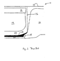
- Fig. 1 Prior to startup, continuous inkjet printers have fluid droplets having a state of no charge potential. In this state, the fluid droplets flow in the direction illustrated in Fig. 1. At some point in the startup sequence, the droplets will have a charge potential applied such that their directionality changes from hitting at the bottom of the catcher (interface of the eyelid seal and catch pan assembly) to being caught on the catcher surface depending upon the level of charge. This is illustrated in Fig. 2. However, if the level of charge is too low, not all of the droplets will be deflected onto the catcher face. Conversely, if the charge is too high, the droplets could be deflected into the charge plate and/or short detect level circuitry, causing a charge short.
- FIG. 1 there is illustrated a prior art view of a drop generator and catcher assembly 10.
- a drop generator 12 is situated in an area above a catcher 14 and charge plate 15, and an eyelid 16.
- the eyelid When the eyelid is in the open position, ink drops are allowed to exit the printhead.
- the eyelid When the eyelid is moved to the closed position, as shown in Fig. 1, the eyelid seal 18 presses against the bottom edge of the catcher plate 20 to contain ink 22 within the printhead on startup and shutdown of the printer system.
- the uncharged ink droplets flow along a trajectory path indicated by 26 in Fig. 1.
- the ink striking the eyelid 16 is diverted by the eyelid into the fluid channel 24 of the of the catcher. This ink flow through the fluid channel is primarily along the lower surface of the fluid channel, defined by the catcher plate 20.
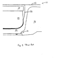
- the ink drops Upon startup, the ink drops become charged, changing the trajectory path of the droplets as indicated by 28 in Fig. 2.
- the ink drops strike the face of the catcher 14 and flow down the face of the catcher, around the catcher radius 27, and into the fluid channel 24 of the catcher.
- the fluid flow through the fluid channel under these conditions is primarily along the upper surface of the fluid channel, defined by the surface of the catcher.
- a heater to heat up the charge plate and catcher of the ink jet printhead. Heating the charge plate and catcher while printing is known to eliminate condensation on the charge plate and catcher face that can lead to printhead failures.
- one state can cause condensation to form on the charging electrodes.
- the condensate serves to dissolve and rinse away ink residue from the charging electrodes to prevent charge plate shorts. After the condensate has appropriately rinsed the charging electrodes, the charge plate and catcher are heated up to prevent further condensation from forming.
- the use of a heater attached to the charge plate and catcher effectively carries out these functions.
- the plot 30 illustrates the spread in these charge voltage conditions from printhead to printhead.
- the three curves 32, 34, and 36 correspond to the number of the printheads (vertical axis) having the horizontal axis charge voltage value as their LAC voltage, OPVolt and Crash voltages, respectively.
- the data points below the charge voltage scale in Fig. 3 show the charge voltage of two different printheads, A and B.
- the LAC voltage, OpVolt and Crash voltage for printhead A are shown at points 38, 40 and 42, respectively.
- the LAC voltage, OpVolt and Crash voltage are shown at points 44, 46 and 48, respectively.
- the LAC voltage is about 120 volts and the OpVolt is about 135.
- the value S would need to be approximately 15 volts or less to keep the startup voltage above the LAC voltage for that printhead.
- the first charge potential As a result of this thermal expansion issue, as well as drop deflection overshoot due to conditions such as charge voltage overshoot, it is desirable to have the first charge potential well below the OpVolt. But as discussed previously, too low of a charge voltage can result in jets not going into catch, with the attendant problems. It is therefore necessary to ensure that the first charge potential be greater than or equal to the LAC for the printhead. Due to the large variability between the LAC and OpVolt from printhead to printhead, the ideal first charge potential is not well approximated by a fixed voltage shift down from the OPVolt condition.
- the LAC voltage level be determined along with the OpVolt condition during printhead assembly or during regular operation of the printhead. These charge voltage conditions can then be stored in memory located either in the printer or the printhead. Then, in accordance with the present invention, the printer controller that manages the startup sequence uses the stored LAC value to define the first charge potential value. In a preferred embodiment, the controller would define the First Charge Voltage equal to the LAC voltage.
- the use of the LAC voltage for deflecting the charged droplets onto the catcher surface enhances the reliability of the startup sequence for printheads having droplets of high speed and flow rate, contained within the narrow confines of the eyelid seal and catch pan assembly, for return to the fluid system under vacuum.
- By going from a state where all of the droplets are hitting in the eyelid seal and catch pan assembly to a state where all of the droplets are being deflected and caught on the catcher face, will help to eliminate the possibility of splatter on the charge plate electrodes and/or the charge short detect level circuitry, ink on top of the eyelid seal, and wicking of ink out of the eyelid.
- FCV First Catch Voltage
- the present invention has been described with reference to an embodiment wherein the ICV is greater than the operating voltage, which is greater than the lowest all catch voltage. This is valid for printers that employ positive charge voltages applied to the charging electrodes, but not for printers that utilize negative charge voltages. It should be noted, however, that the present invention applies to both positive and negative charging voltages, and the various charge voltage conditions, such as ICV, operating voltage, and lowest all catch voltage, can be applied to both charging polarity conditions. In accordance with the present invention, the terms can be defined as voltage magnitudes.
Landscapes
- Particle Formation And Scattering Control In Inkjet Printers (AREA)
Applications Claiming Priority (2)
| Application Number | Priority Date | Filing Date | Title |
|---|---|---|---|
| US254354 | 1994-06-03 | ||
| US10/254,354 US6793327B2 (en) | 2002-09-25 | 2002-09-25 | Low catch voltage startup |
Publications (2)
| Publication Number | Publication Date |
|---|---|
| EP1403048A1 true EP1403048A1 (fr) | 2004-03-31 |
| EP1403048B1 EP1403048B1 (fr) | 2006-11-29 |
Family
ID=31977822
Family Applications (1)
| Application Number | Title | Priority Date | Filing Date |
|---|---|---|---|
| EP03255930A Expired - Lifetime EP1403048B1 (fr) | 2002-09-25 | 2003-09-23 | Démarrage avec une tension d'interception basse |
Country Status (3)
| Country | Link |
|---|---|
| US (1) | US6793327B2 (fr) |
| EP (1) | EP1403048B1 (fr) |
| DE (1) | DE60309995T2 (fr) |
Families Citing this family (3)
| Publication number | Priority date | Publication date | Assignee | Title |
|---|---|---|---|---|
| JP2004210178A (ja) * | 2003-01-07 | 2004-07-29 | Honda Motor Co Ltd | 車体フレーム |
| US7144102B2 (en) * | 2004-05-05 | 2006-12-05 | Eastman Kodak Company | Supression of Marangoni Effect on the catcher face |
| US7331658B2 (en) | 2006-06-19 | 2008-02-19 | Eastman Kodak Company | Anti-wicking catcher assembly and printing system |
Citations (5)
| Publication number | Priority date | Publication date | Assignee | Title |
|---|---|---|---|---|
| US4245226A (en) * | 1979-07-06 | 1981-01-13 | The Mead Corporation | Ink jet printer with heated deflection electrode |
| US4598299A (en) * | 1982-11-11 | 1986-07-01 | Ricoh Company, Ltd. | Deflection control ink jet printing apparatus |
| US5481288A (en) * | 1987-10-30 | 1996-01-02 | Linx Printing Technologies Plc | Modulation signal amplitude adjustment for an ink jet printer |
| EP0744292A2 (fr) * | 1995-05-16 | 1996-11-27 | Videojet Systems International, Inc. | Procédé et appareil de réglage automatique de la tension de commande des buses dans une imprimante à jet d'encre |
| EP0813974A2 (fr) * | 1996-06-18 | 1997-12-29 | SCITEX DIGITAL PRINTING, Inc. | Tête d'impression par jet d'encre continu |
Family Cites Families (1)
| Publication number | Priority date | Publication date | Assignee | Title |
|---|---|---|---|---|
| US5475411A (en) * | 1992-05-29 | 1995-12-12 | Scitex Digital Printing, Inc. | Method of fabricating a catcher/charge plate assembly |
-
2002
- 2002-09-25 US US10/254,354 patent/US6793327B2/en not_active Expired - Lifetime
-
2003
- 2003-09-23 DE DE60309995T patent/DE60309995T2/de not_active Expired - Lifetime
- 2003-09-23 EP EP03255930A patent/EP1403048B1/fr not_active Expired - Lifetime
Patent Citations (5)
| Publication number | Priority date | Publication date | Assignee | Title |
|---|---|---|---|---|
| US4245226A (en) * | 1979-07-06 | 1981-01-13 | The Mead Corporation | Ink jet printer with heated deflection electrode |
| US4598299A (en) * | 1982-11-11 | 1986-07-01 | Ricoh Company, Ltd. | Deflection control ink jet printing apparatus |
| US5481288A (en) * | 1987-10-30 | 1996-01-02 | Linx Printing Technologies Plc | Modulation signal amplitude adjustment for an ink jet printer |
| EP0744292A2 (fr) * | 1995-05-16 | 1996-11-27 | Videojet Systems International, Inc. | Procédé et appareil de réglage automatique de la tension de commande des buses dans une imprimante à jet d'encre |
| EP0813974A2 (fr) * | 1996-06-18 | 1997-12-29 | SCITEX DIGITAL PRINTING, Inc. | Tête d'impression par jet d'encre continu |
Also Published As
| Publication number | Publication date |
|---|---|
| DE60309995D1 (de) | 2007-01-11 |
| DE60309995T2 (de) | 2007-09-20 |
| EP1403048B1 (fr) | 2006-11-29 |
| US6793327B2 (en) | 2004-09-21 |
| US20040056933A1 (en) | 2004-03-25 |
Similar Documents
| Publication | Publication Date | Title |
|---|---|---|
| EP0577186B1 (fr) | Tête d'enregistrement par injection d'un liquide et appareil d'enregistrement équipé avec cette tête | |
| US9114611B2 (en) | Printing apparatus and ink discharge state determination method | |
| JP4243057B2 (ja) | Cmos工程で形成したヒーター要素を有するcmos/mems集積型インクジェット印刷ヘッド及びその製造方法 | |
| US8336981B2 (en) | Determining a healthy fluid ejection nozzle | |
| JP4594516B2 (ja) | 連続インクジェットプリンタのインクの偏向制御装置及び偏向改善方法 | |
| JP3504367B2 (ja) | インク・ジェット・プリンタのための電圧降下用修正装置 | |
| JPH1034976A (ja) | インク記録装置のために記録ヘッドを選択的にメンテナンスする装置 | |
| JP2013136234A (ja) | 記録装置 | |
| JPH0117862B2 (fr) | ||
| JP2004345351A (ja) | サーマルインクジェットプリントヘッドにおけるインク温度制御方法及びそのシステム | |
| EP1403048B1 (fr) | Démarrage avec une tension d'interception basse | |
| US6527355B1 (en) | Method and apparatus for preventing banding defects caused by drop mass variations in an ink jet printer | |
| KR20190019834A (ko) | 고장난 잉크젯들의 복구를 위한 방법 및 시스템 | |
| US6293644B1 (en) | Method and apparatus for preventing satellite induced banding in an ink jet printer using pre-pulse compensation | |
| JP3572866B2 (ja) | インクジェット記録装置およびその制御方法 | |
| US7270389B2 (en) | Ink jet recording apparatus and ink jet recording method | |
| US6276777B1 (en) | Variable maximum operating temperature for a printhead | |
| US20040179070A1 (en) | Ink-jet recording head and ink-jet recording apparatus | |
| US20030202053A1 (en) | Continuous stream ink jet printer with mechanism for asymmetric heat deflection at reduced ink temperature and method of operation thereof | |
| JPH10138513A (ja) | インクジェット記録装置 | |
| EP1403060B1 (fr) | Démarrage à rampe de pression rapide | |
| JPH0820110A (ja) | サーマルインクジェットプリンタ | |
| US20080218544A1 (en) | Ink-jet type image-forming apparatus and ink-jet type image-forming method | |
| JPH11192708A (ja) | 静電インク滴偏向機能を備えたコンティニュアス・インクジェットプリンタ | |
| JP2001150679A (ja) | インクジェットプリントヘッド |
Legal Events
| Date | Code | Title | Description |
|---|---|---|---|
| PUAI | Public reference made under article 153(3) epc to a published international application that has entered the european phase |
Free format text: ORIGINAL CODE: 0009012 |
|
| AK | Designated contracting states |
Kind code of ref document: A1 Designated state(s): AT BE BG CH CY CZ DE DK EE ES FI FR GB GR HU IE IT LI LU MC NL PT RO SE SI SK TR |
|
| AX | Request for extension of the european patent |
Extension state: AL LT LV MK |
|
| RAP1 | Party data changed (applicant data changed or rights of an application transferred) |
Owner name: EASTMAN KODAK COMPANY |
|
| 17P | Request for examination filed |
Effective date: 20040911 |
|
| AKX | Designation fees paid |
Designated state(s): DE FR GB |
|
| GRAP | Despatch of communication of intention to grant a patent |
Free format text: ORIGINAL CODE: EPIDOSNIGR1 |
|
| GRAS | Grant fee paid |
Free format text: ORIGINAL CODE: EPIDOSNIGR3 |
|
| GRAA | (expected) grant |
Free format text: ORIGINAL CODE: 0009210 |
|
| AK | Designated contracting states |
Kind code of ref document: B1 Designated state(s): DE FR GB |
|
| REG | Reference to a national code |
Ref country code: GB Ref legal event code: FG4D |
|
| REF | Corresponds to: |
Ref document number: 60309995 Country of ref document: DE Date of ref document: 20070111 Kind code of ref document: P |
|
| ET | Fr: translation filed | ||
| PLBE | No opposition filed within time limit |
Free format text: ORIGINAL CODE: 0009261 |
|
| STAA | Information on the status of an ep patent application or granted ep patent |
Free format text: STATUS: NO OPPOSITION FILED WITHIN TIME LIMIT |
|
| 26N | No opposition filed |
Effective date: 20070830 |
|
| PGFP | Annual fee paid to national office [announced via postgrant information from national office to epo] |
Ref country code: FR Payment date: 20120910 Year of fee payment: 10 |
|
| PGFP | Annual fee paid to national office [announced via postgrant information from national office to epo] |
Ref country code: GB Payment date: 20130827 Year of fee payment: 11 |
|
| REG | Reference to a national code |
Ref country code: FR Ref legal event code: ST Effective date: 20140530 |
|
| PG25 | Lapsed in a contracting state [announced via postgrant information from national office to epo] |
Ref country code: FR Free format text: LAPSE BECAUSE OF NON-PAYMENT OF DUE FEES Effective date: 20130930 |
|
| PGFP | Annual fee paid to national office [announced via postgrant information from national office to epo] |
Ref country code: DE Payment date: 20140930 Year of fee payment: 12 |
|
| GBPC | Gb: european patent ceased through non-payment of renewal fee |
Effective date: 20140923 |
|
| PG25 | Lapsed in a contracting state [announced via postgrant information from national office to epo] |
Ref country code: GB Free format text: LAPSE BECAUSE OF NON-PAYMENT OF DUE FEES Effective date: 20140923 |
|
| REG | Reference to a national code |
Ref country code: DE Ref legal event code: R119 Ref document number: 60309995 Country of ref document: DE |
|
| PG25 | Lapsed in a contracting state [announced via postgrant information from national office to epo] |
Ref country code: DE Free format text: LAPSE BECAUSE OF NON-PAYMENT OF DUE FEES Effective date: 20160401 |