EP1411775B1 - Procede de vidage de poissons etetes ou non etetes et dispositif de mise en oeuvre dudit procede - Google Patents
Procede de vidage de poissons etetes ou non etetes et dispositif de mise en oeuvre dudit procede Download PDFInfo
- Publication number
- EP1411775B1 EP1411775B1 EP02767258A EP02767258A EP1411775B1 EP 1411775 B1 EP1411775 B1 EP 1411775B1 EP 02767258 A EP02767258 A EP 02767258A EP 02767258 A EP02767258 A EP 02767258A EP 1411775 B1 EP1411775 B1 EP 1411775B1
- Authority
- EP
- European Patent Office
- Prior art keywords
- entrails
- suction
- blood
- vacuum unit
- suction nozzle
- Prior art date
- Legal status (The legal status is an assumption and is not a legal conclusion. Google has not performed a legal analysis and makes no representation as to the accuracy of the status listed.)
- Expired - Lifetime
Links
- 238000000034 method Methods 0.000 title claims description 36
- 241000251468 Actinopterygii Species 0.000 title claims description 33
- 210000004369 blood Anatomy 0.000 claims description 46
- 239000008280 blood Substances 0.000 claims description 46
- XLYOFNOQVPJJNP-UHFFFAOYSA-N water Substances O XLYOFNOQVPJJNP-UHFFFAOYSA-N 0.000 claims description 31
- 210000000683 abdominal cavity Anatomy 0.000 claims description 28
- 239000012528 membrane Substances 0.000 claims description 20
- 210000003734 kidney Anatomy 0.000 claims description 14
- 210000000436 anus Anatomy 0.000 claims description 9
- 210000003815 abdominal wall Anatomy 0.000 claims description 6
- 238000007790 scraping Methods 0.000 claims description 6
- 238000012545 processing Methods 0.000 claims description 5
- 210000000988 bone and bone Anatomy 0.000 claims description 4
- 230000001105 regulatory effect Effects 0.000 claims description 2
- 230000002093 peripheral effect Effects 0.000 claims 2
- 238000000151 deposition Methods 0.000 claims 1
- 238000000605 extraction Methods 0.000 claims 1
- 210000003750 lower gastrointestinal tract Anatomy 0.000 claims 1
- 235000019688 fish Nutrition 0.000 description 25
- 210000000936 intestine Anatomy 0.000 description 14
- 210000004379 membrane Anatomy 0.000 description 14
- 210000001835 viscera Anatomy 0.000 description 9
- 239000003795 chemical substances by application Substances 0.000 description 6
- 238000003307 slaughter Methods 0.000 description 3
- 230000000903 blocking effect Effects 0.000 description 2
- 238000000354 decomposition reaction Methods 0.000 description 2
- 238000011161 development Methods 0.000 description 2
- 230000018109 developmental process Effects 0.000 description 2
- 238000007599 discharging Methods 0.000 description 2
- 238000012544 monitoring process Methods 0.000 description 2
- 238000011084 recovery Methods 0.000 description 2
- 238000000926 separation method Methods 0.000 description 2
- 241000972773 Aulopiformes Species 0.000 description 1
- 241000277263 Salmo Species 0.000 description 1
- 238000011109 contamination Methods 0.000 description 1
- 238000010924 continuous production Methods 0.000 description 1
- 230000001419 dependent effect Effects 0.000 description 1
- 238000005137 deposition process Methods 0.000 description 1
- 230000000694 effects Effects 0.000 description 1
- 239000012530 fluid Substances 0.000 description 1
- 239000007788 liquid Substances 0.000 description 1
- 230000003287 optical effect Effects 0.000 description 1
- 210000003200 peritoneal cavity Anatomy 0.000 description 1
- 230000001737 promoting effect Effects 0.000 description 1
- 210000000664 rectum Anatomy 0.000 description 1
- 235000019515 salmon Nutrition 0.000 description 1
- 230000002000 scavenging effect Effects 0.000 description 1
- 238000012216 screening Methods 0.000 description 1
Images


Classifications
-
- A—HUMAN NECESSITIES
- A22—BUTCHERING; MEAT TREATMENT; PROCESSING POULTRY OR FISH
- A22C—PROCESSING MEAT, POULTRY, OR FISH
- A22C25/00—Processing fish ; Curing of fish; Stunning of fish by electric current; Investigating fish by optical means
- A22C25/14—Beheading, eviscerating, or cleaning fish
-
- A—HUMAN NECESSITIES
- A22—BUTCHERING; MEAT TREATMENT; PROCESSING POULTRY OR FISH
- A22C—PROCESSING MEAT, POULTRY, OR FISH
- A22C25/00—Processing fish ; Curing of fish; Stunning of fish by electric current; Investigating fish by optical means
- A22C25/14—Beheading, eviscerating, or cleaning fish
- A22C25/145—Eviscerating fish
- A22C25/147—Eviscerating by means of vacuum or suction devices
Definitions
- the invention relates to a method for gutting beheaded and uncooked fish, especially of farmed fish, comprising the steps of opening the abdominal cavity by means of circular knives with Leitstichel, scraping and sucking the then partially dissolved entrails by means of a suction nozzle, opening the membrane of the blood kidney, aspiration of blood and water by means of suction scrapers and suction of viscera and blood and water via suction lines.
- the invention relates to a device, in particular for carrying out the method, essentially comprising a conveyor with at least one fish intake for receiving the fish to be processed and promoting the same in the direction of the processing station, arranged in the region of the conveyor means for opening the abdominal cavity, for Ausschaben and suction of the viscera, complete opening of the membrane of the blood kidney and aspiration of blood and water, and aspiration of viscera and blood and water from the abdominal cavity.
- Such a method with a corresponding device for slaughtering and gutting the fish is known from the document DE 198 29 376.
- a stylus moves into the anal opening and forms the incision counter for a circular knife, which opens the abdominal wall of the fish in the longitudinal direction. So that the circular blade can emerge unhindered from the fish, the graver is swung back at the end of the cut.
- a first suction nozzle with open suction opening moves into the abdominal cavity, wherein a ball valve is closed in the suction line to build up negative pressure in the suction line.
- the ball valve opens at the earliest when the suction nozzle has reached the bottom of the abdominal cavity.
- a blade opens the membrane of the blood kidney from the Banch fins to the end of the abdominal cavity.
- a subsequent second tool opens the blood kidney in the back (from the anus to the pelvic fins) and removes blood and water in this area.
- Another downstream third tool cleans the front area of the abdominal cavity (from the ventral fins to the end of the abdominal cavity) of blood and water by covering it with the previous tool.
- a central vacuum device which consists of a vacuum pump with a filter, a cyclone and piping. Guts, blood and water are separated in the cyclone from the air flow and continuously collected from an eccentric screw pump or the like from this.
- the known method and the known device have the disadvantage that the further utilization of the intestines is limited or not at all possible, since entrails, blood and water, inter alia, due to the high transport speed in the pipelines, the deposition process and the discharge via the eccentric screw pump, as a homogeneous, pulpy mass.
- the known device also has the disadvantage that the blade of the suction nozzle for opening the membrane of the blood kidney also slits the viscera in the longitudinal direction, so that they are damaged or blood and other fluids can escape from the blood kidney and the guts, the decomposition of the same or contaminate the exploitable components.
- the invention is thus based on the object to propose a method for gutting beheaded and uncooked fish, which ensures the further utilization of the intestines. Furthermore, it is an object of the invention to provide a device which enables the implementation of the method according to the invention in a simple manner.
- the object of the invention is achieved by a method together with the steps mentioned above in that the intestines on the one hand and blood and water on the other hand be collected separately from each other. As a result, the mixing of all components is excluded to a homogeneous mass, so that at least the separately discharged entrails can be supplied to a further recovery.
- the suction nozzle is connected to a first vacuum unit with high negative pressure during the suction of the entrails. This ensures that the intestines can be removed completely and as a unit from the abdominal cavity.
- a changeover from the first vacuum unit to a second vacuum unit which has a lower negative pressure compared to the first vacuum unit, wherein a slide is opened after switching to the second vacuum unit.
- the entrails are guided at very low speed into a separate collecting container, the entrails impinging at a shallow angle to the wall of the collecting container and sliding downwardly in the latter.
- the entrails get gently on the container bottom.
- the suction scrapers for discharging blood and water are connected to the first vacuum unit.
- blood and water are supplied to the first vacuum unit, more specifically the cyclone, so that mixing with the entrails resulting in contamination thereof is prevented.
- the abdominal wall is pulled upwards when opening the abdominal cavity after entering the anal opening, ie away from the intestines. This eliminates the risk of possible damage to the viscera, which would prevent further recovery.
- the object is achieved by a device with the features of the preamble of claim 20, characterized in that the means for suction and suction of the intestines on the one hand and the means for suction and suction of the blood and water on the other hand via separate lines with separate collection containers are connected. This separation of individual components enables further utilization
- all means for suction and suction of the viscera and blood and water are connected to a first vacuum unit, wherein the means for suction and suction of the viscera are additionally connected to a second vacuum unit.
- This ensures the possibility to perform the suction of the viscera with the first vacuum unit, which has a relation to the second vacuum unit higher negative pressure, so that the entrails can be completely removed as a block, while the suction of the entrails by means of the second vacuum unit with low Low pressure can be done in a gentle manner. Due to the temporary separation of the suction nozzle during suction from the central suction line leading to the first vacuum unit, the entrails are exposed to only small forces, so that the integrity of the entrails is ensured, without affecting the function of the suction.
- connection between the means for suction and aspiration of the viscera namely the suction nozzle and the two vacuum units selectively switchable, so that a continuous process can be maintained, in each case the required negative pressure depending on the desired process step can be applied.
- the collecting container for the entrails of a particularly preferred embodiment of the invention is designed or arranged such that the entrails impinge at a shallow angle on the lateral surface of the collecting container, so that the entrails then slide gently down on this.
- a gentle treatment of the intestines is gesergetsellt within the collection container.
- the suction nozzle on a blade for opening the membrane of the blood kidney which is designed such that damage to the intestines in the longitudinal direction is prevented. This prevents in a simple way that in particular a decomposition of the intestines takes place by liquids from the innards.
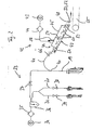
- the device according to the figures 1 to 5 is used for gutting beheaded and uncooked fish, especially of farmed fish such as those of the Salmo species.
- the device 10 shown in particular in Figure 1 is substantially constructed, as the already known apparatus for slaughtering salmon, so that a detailed description of the device 10 itself is unnecessary. Only for a better understanding, essential components are listed.
- the device has a conveyor 11, with which the fish tail are advanced and with the dorsal fin down. But other layers of fish are feasible.
- a measuring device 13 In the transport direction behind the inlet position 12, a measuring device 13, a means for opening the abdominal cavity, namely a circular blade 14 with Leitstichel 15, a suction nozzle 16 and suction scrapers 17 and 18 are successively arranged.
- the suction nozzle 16 and the suction scrapers 17 and 18 are connected via suction lines 19, 20 and 21 with a vacuum unit.
- the suction nozzle 16 for scraping and suction of the intestines has a hollow body 22 which serves to receive the intestines.
- the suction nozzle 16 itself can be closed with a guillotine-like slide 23.
- the suction nozzle 16 has a blade 25 for opening the membrane 26 of the blood kidney approximately from the ventral fins 27 to the end of the abdominal cavity 28.
- the blade 25 is designed such that the so-called base run of the suction nozzle 16 with the blade 25 on the middle burr 24 takes place.
- the blade 25 has a cover 29, the plow-like between entrails 30 on the one hand and diaphragm 26 engages and separates them.
- the suction scraper 17 for opening the membrane 26 from about the anus 31 to the ventral fins 27 is also formed as a hollow body 32, wherein blood and water are sucked through this and.
- the suction scraper 18 following the suction scraper 17 in the transport direction serves, in particular, for scavenging, sucking in and sucking off the residues of blood and water left by the suction nozzle 16.
- the suction lines 19 to 21 are all connected to a first vacuum unit 33.
- the vacuum unit 33 consists essentially of a vacuum pump 34, a filter 35 and a collecting container, namely in particular a cyclone 36.
- a blocking means in particular a ball valve 37, 38 and 39, respectively.
- a branch is formed in the suction line 19, which connects the suction nozzle 16 with the first vacuum unit 33. This branch in the region of a switch 40 is arranged in the conveying direction of the entrails 30 in front of the ball valve 37.
- the switch 40 leads the suction line 19 of the suction nozzle 16 via a further suction line 41 to a second, separate vacuum unit 42.
- the second vacuum unit 42 also consists essentially of a vacuum pump 43, a filter 44 and a collecting container 45.
- the vacuum unit 42 has with respect to Vacuum unit 33 has a lower negative pressure, so that within the suction line 19 and 41 for sucking the entrails 30, a lower transport speed is achieved.
- a further blocking means in particular a ball valve 46 is arranged between the switch 40 and the collecting container 45.
- the collecting container 45 is specially designed so that the incoming entrails 30 impinge on the lateral surface 47 on the inside at a shallow angle ⁇ .
- the collecting container 45 itself is formed U-shaped in the illustrated embodiment, wherein the lateral surface 47 is circumferentially closed. However, the collecting container 45 may also have any other desired shape.
- the inclined with its longitudinal axis 48 arranged collecting container 45 is also closed at the end faces 49 and 50. In the inlet area 51, only the access of the Sang Arthur 42 is provided. In the outlet region 52 of the collecting container 45 by a pivotable flap 53, a slide or the like either open or close.
- a release agent 54 is arranged approximately in the middle, with which the collecting container 45 is divisible.
- the separating means 54 can be arranged at any position and designed as a flap, slide or the like.
- a transport and / or sieve belt 55 is arranged, on which the entrails 30 can be deposited.
- a means 56 for detecting the filling level of the collecting container 45 is arranged.
- the means 56 may be formed as a sensor. Other common optical, mechanical or other non-contact monitoring means may also be used.
- the entire apparatus 10 has a (not shown) computer unit for control and / or regulation, by means of which all components are controlled mutually coordinated and the function sequence can be freely programmed and executed, so that individual adjustments made in terms of the procedure in a simple manner can be.
- the ball valves 37 and 46 are replaced in the suction lines 19 and 42 by a single 2/3-way stopcock.
- the 2/3-way stopcock is arranged in the region of the switch 40 and can also be controlled via the higher-level control and / or regulating unit.
- the suction nozzle 16 lowers in the open state, ie with open slide 23 in the abdominal cavity 28, approximately in the area of the ventral fins 27.
- the ball valve 37 in the suction line 19 is to build up a negative pressure within the cyclone 36 and the section the suction line 19 between the ball valve 37 and the cyclone 36 is closed.
- the suction nozzle 16 is lowered so far down that the suction nozzle 16 is placed with its blade 25 on the center bone 24.
- the entrails 30 are now released by the superimposed transport speed, pushed together and in the hollow body 22 of the Suction nozzle 16 collected.
- the ball valve 37 is opened as late as possible, so only shortly before the end 60 of the abdominal cavity 28, so that a large suction effect (due to the high negative pressure in the cyclone 36 and the portion of the suction line 19 between the ball valve 37 and the cyclone 36) within the entire suction line 19 is formed.
- the membrane 26 When threading the suction nozzle 16 into the abdominal cavity 28 or when placing the blade 25 on the central bone 24, the membrane 26 is severed or pierced by the crescent-shaped blade 25.
- the sickle shape of the blade 25 causes the membrane 26 slips up, but only up to under the cover 29 (state, see Figure 3).
- the cover 29 pushes between the entrails 30 and the membrane 26 (see in particular Figures 3 and 4).
- the connection of the suction nozzle 16 is separated with the first vacuum unit 33 and the suction nozzle 16 is connected to the second vacuum unit 42.
- This switching is done by the ball valve 37 is closed and the ball valve 46, which was previously closed because of build-up of vacuum in the collecting container and the suction line 41, is opened.
- the slider 23 is opened, so that the entrails 30, now with a lower because of the lower vacuum of the second vacuum unit 42 transport speed into the collecting container 45 are passed.
- the entrails 30 guided at a very low speed into the collecting container 45 strike the lateral surface 47 at a shallow angle ⁇ (see in particular FIG. 2) and slide in the direction of the bottom flap.
- the entrails 30 initially slide against a release agent 54, which dammed the entrails 30 of several fish to form a filling 61.
- the means 56 for monitoring the level or the filling amount 61 signals when the front chamber is filled.
- the bottom flap 53 must be closed, so that the release agent 54 can be opened while maintaining the negative pressure in the collecting container 45.
- the entrails 30 then slip into the lower chamber and are stopped by the bottom flap 53.
- the bottom flap 53 can then be opened for discharging the entrails 30 onto the transporting and / or screening belt 55.
- the release agent 54 is closed until the upper chamber is filled. Only when no entrails 30 can be taken, the release means 54 opens so that the entrails 30 in the lower chamber, which should have at least the same volume to the upper chamber, can slide. Once all entrails 30 have arrived in the lower chamber, the release agent 54 is closed. By means of this lock function, a continuous operation of the device is made possible with the aid of a PLC or a computer unit.
- the suction scraper 17 opens the membrane 26 completely and sucks together with the suction scraper 18, the accumulated blood and water.
- the suction lines 20 and 21 the blood and water are sucked with open ball valves 38, 39 in the cyclone 36.
- the negative pressure for suction and suction of blood and water was previously generated by the closed ball valves 38, 39 in the cyclone 36 and the portions of the suction lines 20, 21 between the ball valves 38, 39 and the cyclone 36. Blood and water enter tangentially in the cyclone 36 and then fall down, particularly due to the reduced air velocity in the cyclone 36.
- the negative pressure of the first vacuum unit 33 which is significantly greater than the negative pressure in the second vacuum unit 42, causes the transport speeds in the suction lines, which are connected to the first vacuum unit 33, by a factor of 10 to 15 higher than in the suction lines which are connected to the second vacuum unit 42. This is a significant reason why the entrails 30 can be obtained intact in the method according to the invention.
Landscapes
- Life Sciences & Earth Sciences (AREA)
- Engineering & Computer Science (AREA)
- Wood Science & Technology (AREA)
- Zoology (AREA)
- Food Science & Technology (AREA)
- External Artificial Organs (AREA)
- Medicines Containing Material From Animals Or Micro-Organisms (AREA)
Claims (37)
- Procédé d'éviscération de poissons étêtés ou non étêtés, en particulier de poissons d'élevage, lequel procédé comporte les étapes consistant à :- ouvrir la cavité abdominale (28) au moyen de couteaux circulaires (14) dotés de lames directrices (15),- gratter et aspirer les viscères (30) alors partiellement détachées au moyen d'une buse d'aspiration (16),- ouvrir la membrane (26) du rein et aspirer le sang et l'eau au moyen de grattoirs aspirateurs (17, 18),- évacuer par aspiration les viscères (30), le sang et l'eau par des conduites d'aspiration (19, 20, 21),caractérisé en ce que les viscères (30) d'une part et le sang et l'eau d'autre part sont collectés séparément.
- Procédé selon la revendication 1, caractérisé en ce que l'ouverture de la cavité abdominale (28) est effectuée longitudinalement à la paroi abdominale de la cavité abdominale (28) de l'anus (31) au gros intestin (60) dans la région des ailerons latéraux en détachant le gros intestin au niveau de l'anus (31).
- Procédé selon la revendication 1 ou 2, caractérisé en ce que le grattage et l'aspiration des viscères (30) sont effectués le long l'arête centrale (24) du poisson, les viscères partiellement détachées (30) étant aspirées simultanément, et la membrane (26) du rein étant partiellement ouverte au moyen d'une lame (25) disposée dans la région de la buse d'aspiration (16).
- Procédé selon l'une des revendications 1 à 3, caractérisé en ce que la buse d'aspiration (16) est reliée à une première unité de dépression (33), générant une dépression élevée, pendant l'aspiration des viscères (30).
- Procédé selon la revendication 4, caractérisé en ce que la dépression est générée en fermant un robinet à obturateur sphérique (37) ou analogue dans l'unité de dépression (33), en particulier dans un cyclone (36) et la portion de la conduite d'aspiration (19) entre un robinet à obturateur sphérique (37) et le cyclone (36).
- Procédé selon l'une des revendications 1 à 5, caractérisé en ce que la buse d'aspiration (16), à l'extrémité de la cavité abdominale (28), est fermée par une vanne d'arrêt (23) dotée d'un couteau de sorte que les viscères (30), totalement séparées du corps du poisson, sont logées dans la buse d'aspiration (16).
- Procédé selon l'une des revendications 1 à 6, caractérisé en ce que, pendant la montée de la buse d'aspiration (16) pour sortir du poisson, il est effectué une commutation de la première unité de dépression (33) à une deuxième unité de dépression (42), qui est générée une dépression inférieure à celle de la première unité de dépression (33), la vanne d'arrêt (23) étant ouverte après la commutation sur la deuxième unité de dépression (42).
- Procédé selon l'une des revendications 1 à 7, caractérisé en ce que les viscères (30) sont amenées à très faible vitesse dans un récipient de collecte (45) séparé du cyclone (36) afin de recevoir le sang et l'eau.
- Procédé selon l'une des revendications 1 à 8, caractérisé en ce que les viscères (30) rencontrent la surface d'enveloppe (47) du récipient de collecte (45) avec un dièdre α et glisse vers le bas sur cette surface d'enveloppe en direction d'une trappe de fond (53).
- Procédé selon l'une des revendications 1 à 9, caractérisé en ce que l'état de remplissage du récipient de collecte (45) est surveillé.
- Procédé selon l'une des revendications 1 à 10, caractérisé en ce que, lorsque le récipient de collecte (45) est rempli, un moyen de séparation (54) est fermé avant l'ouverture de la trappe de fond (53) destinée à déposer au moins partiellement les viscères (30) sur une bande de transport et/ou de tamisage (55) à l'intérieur du récipient de collecte (45) de façon à maintenir la dépression à l'intérieur du récipient de collecte (45).
- Procédé selon l'une des revendications précédentes 1 à 11, caractérisé en ce que la buse d'aspiration (16) est de nouveau raccordée à la première unité de dépression (33) après l'aspiration des viscères (30) en effectuant une nouvelle commutation de façon à pouvoir aspirer les viscères (30) d'un poisson suivant.
- Procédé selon la revendication 12, caractérisé en ce qu'une dépression est de nouveau générée par l'unité de dépression (33) en fermant le robinet à obturateur sphérique (37) avant l'aspiration des viscères (30).
- Procédé selon l'une des revendications 1 à 13, caractérisé en ce que la membrane (26) du rein est totalement ouverte par le grattoir aspirateur (17).
- Procédé selon l'une des revendications 1 à 14, caractérisé en ce que le grattoir aspirateur (17, 18) est raccordé à la première unité de dépression (33) afin d'évacuer le sang et l'eau.
- Procédé selon l'une des revendications 1 à 15, caractérisé en ce qu'une dépression est générée dans les conduites d'aspiration (20, 21) entre les grattoirs aspirateurs (17, 18) et la première unité de dépression (33) en fermant les robinets à obturateur sphérique (38, 39) ou analogues.
- Procédé selon l'une des revendications 1 à 16, caractérisé en ce que le sang et l'eau sont amenés dans le cyclone (36), le sang et l'eau arrivant tangentiellement dans le cyclone (36).
- Procédé selon l'une des revendications 1 à 19, caractérisé en ce que la paroi abdominale est tirée vers le haut, donc en s'écartant des viscères (30), lors de l'ouverture de la cavité abdominale (28) après l'entrée dans l'ouverture anale.
- Procédé selon l'une des revendications 1 à 18, caractérisé en ce que, lors du passage de la lame de coupe (25) afin d'ouvrir la membrane (26) du rein, les viscères (30) ne sont pas touchées par la lame (25) de la buse d'aspiration (16).
- Dispositif, destiné en particulier à mettre en oeuvre le procédé selon les revendications 1 à 19, ledit dispositif comportant essentiellement un transporteur (11) doté d'au moins un logement de poisson (57) destiné à recevoir le poisson à traiter et à transporter celui-ci en direction de la station de traitement, des moyens (14, 15, 16, 17, 18) disposés dans la région du transporteur (11) et destinés à ouvrir la cavité abdominale (28), à gratter et aspirer les viscères (30), à ouvrir totalement la membrane (26) du rein et à aspirer le sang et l'eau ainsi qu'à évacuer par aspiration les viscères (30), le sang et l'eau de la cavité abdominale (28), caractérisé en ce que les moyens (16) destinés à aspirer et évacuer par aspiration les viscères (30) d'une part et les moyens (17, 18) destinés à aspirer et évacuer par aspiration le sang et l'eau d'autre part sont raccordés à des récipients de collecte séparés (36, 45) par des conduites d'aspiration séparées (19, 20, 21 ; 41).
- Dispositif selon la revendication 20, caractérisé en ce que tous les moyens (16, 17, 18) destinés à aspirer et évacuer par aspiration les viscères (30) ainsi que le sang et l'eau sont reliés à une première unité de dépression (33).
- Dispositif selon la revendication 21, caractérisé en ce que la première unité de dépression (33) est essentiellement constituée par une pompe à vide (34) dotée d'un filtre (35), par un cyclone (36) servant de récipient de collecte ainsi que par des conduites d'aspiration (19, 20, 21).
- Dispositif selon l'une des revendications 20 à 22, caractérisé en ce que le moyen (16) destiné à aspirer et évacuer par aspiration les viscères (30) est relié en plus à une deuxième unité de dépression (42).
- Dispositif selon la revendication 23, caractérisé en ce que la deuxième unité de dépression (42) est essentiellement constituée par une pompe à vide (43) dotée d'un filtre (44), par un récipient de collecte (45) ainsi que par des conduites d'aspiration (41).
- Dispositif selon l'une des revendications 20 à 24, caractérisé en ce que la deuxième unité de dépression (42) génère une dépression inférieure à celle de la première unité de dépression (33).
- Dispositif selon l'une des revendications 20 à 25, caractérisé en ce que la liaison entre le moyen d'aspiration et d'évacuation par aspiration des viscères, c'est-à-dire la buse d'aspiration (16), et les deux unités de dépression (33, 42) peut être connectés facultativement.
- Dispositif selon l'une des revendications 20 à 26, caractérisé en ce que les conduites d'aspiration (19, 41) entre la buse d'aspiration (16) et la première unité de dépression (33) d'une part et entre la buse d'aspiration (16) et la deuxième unité de dépression (42) d'autre part sont raccordées l'une à l'autre au niveau d'un aiguillage (40).
- Dispositif selon l'une des revendications 20 à 27, caractérisé en ce qu'un robinet à obturateur sphérique (37, 46) ou analogue est disposé dans chacune des conduites d'aspiration (19, 41) pour commuter entre les unités de dépression (33, 42).
- Dispositif selon l'une des revendications 20 à 27, caractérisé en ce qu'un robinet à 2/3 voies est disposé dans la région de l'aiguillage (40) des conduites d'aspiration (19, 41) pour commuter entre les unités de dépression (33, 42).
- Dispositif selon l'une des revendications 20 à 29, caractérisé en ce qu'un robinet à obturateur sphérique (38, 39) ou analogue est disposé dans chacune des conduites d'aspiration (20, 21) entre les moyens (17, 18) destinés à aspirer et évacuer par aspiration le sang et l'eau, c'est-à-dire les grattoirs aspirateurs et la première unité de dépression (33).
- Dispositif selon l'une des revendications 20 à 30, caractérisé en ce que le récipient de collecte (45) destiné aux viscères (30) est conformé ou disposé de telle sorte que les viscères (30) rencontrent la surface d'enveloppe (47) du récipient de collecte (45) avec un dièdre α de sorte que les viscères (30) glissent ensuite doucement vers le bas sur cette surface d'enveloppe.
- Dispositif selon l'une des revendications 20 à 31, caractérisé en ce qu'un moyen de séparation (54), qui peut être au choix ouvert ou fermé, est disposé à l'intérieur du récipient de collecte (45).
- Dispositif selon l'une des revendications 20 à 32, caractérisé en ce que des moyens (56) destinés à détecter l'état de remplissage du récipient de collecte (45) sont disposés au niveau du récipient de collecte (45).
- Dispositif selon l'une des revendications 20 à 33, caractérisé en ce qu'une bande de transport et/ou de tamisage (55) est disposée en arrière du récipient de collecte (45) par référence au sens de déplacement des viscères (30).
- Dispositif selon l'une des revendications 20 à 34, caractérisé en ce que le dispositif (10) dispose d'une commande permettant de commander et/ou régler chaque composant individuel.
- Dispositif selon l'une des revendications 20 à 35, caractérisé en ce que la buse d'aspiration (16) comporte une lame (25) qui est destinée à ouvrir la membrane (26) du rein et qui est conformée de façon à éviter d'endommager les viscères (30) dans la direction longitudinale.
- Dispositif selon la revendication 36, caractérisé en ce que la lame (25) est dotée d'une protection (29).
Applications Claiming Priority (3)
| Application Number | Priority Date | Filing Date | Title |
|---|---|---|---|
| DE10137647A DE10137647A1 (de) | 2001-08-03 | 2001-08-03 | Verfahren zum Entweiden geköpfter und ungeköpfter Fische und Vorrichtung zur Durchführung desselben |
| DE10137647 | 2001-08-03 | ||
| PCT/EP2002/008268 WO2003013263A1 (fr) | 2001-08-03 | 2002-07-24 | Procede de vidage de poissons etetes ou non etetes et dispositif de mise en oeuvre dudit procede |
Publications (2)
| Publication Number | Publication Date |
|---|---|
| EP1411775A1 EP1411775A1 (fr) | 2004-04-28 |
| EP1411775B1 true EP1411775B1 (fr) | 2006-04-12 |
Family
ID=7693967
Family Applications (1)
| Application Number | Title | Priority Date | Filing Date |
|---|---|---|---|
| EP02767258A Expired - Lifetime EP1411775B1 (fr) | 2001-08-03 | 2002-07-24 | Procede de vidage de poissons etetes ou non etetes et dispositif de mise en oeuvre dudit procede |
Country Status (9)
| Country | Link |
|---|---|
| US (1) | US7427229B2 (fr) |
| EP (1) | EP1411775B1 (fr) |
| CA (1) | CA2454695C (fr) |
| DE (2) | DE10137647A1 (fr) |
| DK (1) | DK176548B1 (fr) |
| IS (1) | IS2383B (fr) |
| NO (1) | NO336236B1 (fr) |
| NZ (1) | NZ530183A (fr) |
| WO (1) | WO2003013263A1 (fr) |
Families Citing this family (19)
| Publication number | Priority date | Publication date | Assignee | Title |
|---|---|---|---|---|
| DE102006021526B3 (de) * | 2006-05-06 | 2007-09-20 | Nordischer Maschinenbau Rud. Baader Gmbh + Co. Kg | Werkzeug, Vorrichtung sowie Verfahren zum Entweiden von in der Bauchhöhle geöffneten Fischen |
| US7179163B1 (en) * | 2006-06-07 | 2007-02-20 | Laitram, L.L.C. | Fish cleaning apparatus and methods |
| WO2008079332A2 (fr) * | 2006-12-21 | 2008-07-03 | Cargill, Incorporated | Scie à vide |
| DE602008006600D1 (de) | 2007-11-12 | 2011-06-09 | Helgi Nolsoe | Vorrichtung zum lösen, trennen und sammeln von organischen materialien |
| JP5646942B2 (ja) * | 2010-10-04 | 2014-12-24 | ユニシーインクUniSea Inc. | 魚体の中骨分断処理方法および装置 |
| US8512106B2 (en) * | 2011-08-08 | 2013-08-20 | Ryco Equipment, Inc. | Fish processing system and method |
| NL2007786C2 (en) * | 2011-11-15 | 2013-05-16 | Marel Stork Poultry Proc Bv | Organ removal device and a method for organ removal. |
| US8986077B1 (en) | 2013-12-17 | 2015-03-24 | Robert M. Ryan | Fish processing system and method |
| US9888697B2 (en) * | 2014-02-03 | 2018-02-13 | Nordischer Maschinenbau Rud. Baader Gmbh + Co. Kg | Method and device for automatically extracting flesh from fish |
| US9635867B2 (en) | 2014-04-15 | 2017-05-02 | Ryco Equipment, Inc. | Fish processing systems and methods |
| US10531668B2 (en) | 2016-04-26 | 2020-01-14 | Nordischer Maschinenbau Rud. Baader Gmbh + Co. Kg | Method and apparatus for inspecting the abdominal cavity of gutted fish |
| EP3448164B1 (fr) * | 2016-04-26 | 2022-08-31 | Nordischer Maschinenbau Rud. Baader GmbH + Co. KG | Outil d'aspiration ainsi que dispositif et procédé pour éviscérer des poisons ouverts dans la cavité abdominale |
| SE542765C2 (en) * | 2016-11-15 | 2020-07-07 | Robot Grader Ab | A portioning device for packaging of food products |
| NO344195B1 (no) | 2018-02-07 | 2019-10-14 | Knuro As | Sløymaskin for fisk og en fremgangsmåte for sløying i en sløyemaskin. |
| EP3581031A1 (fr) * | 2018-06-15 | 2019-12-18 | Kroma A/S | Dispositif et procédé de vidage de poissons à coupe contrôlable |
| CA3135523A1 (fr) * | 2019-05-01 | 2020-11-05 | Kroma A/S | Dispositif de nettoyage de poisson automatique |
| WO2023186270A1 (fr) * | 2022-03-29 | 2023-10-05 | Baader Food Systems Denmark A/S | Dispositif et procédé de coupe d'une carcasse de volaille abattue qui est suspendue par les pattes et déjà découpée dans la zone du cloaque pour créer une ouverture cloacale |
| EP4360460A1 (fr) * | 2022-10-27 | 2024-05-01 | Marel Iceland EHF | Machine et procédé pour retirer une nageoire dorsale d'un poisson |
| CN115804400A (zh) * | 2022-12-21 | 2023-03-17 | 广东若铂智能机器人有限公司 | 一种鳖鱼内脏收集处理系统 |
Family Cites Families (19)
| Publication number | Priority date | Publication date | Assignee | Title |
|---|---|---|---|---|
| US3760457A (en) * | 1971-11-26 | 1973-09-25 | Food Equipment Inc | Eviscerate waste handling system |
| US3908229A (en) * | 1972-01-12 | 1975-09-30 | Gainesville Machine Co Inc | Vacuum eviscerator apparatus and method |
| FR2213017A1 (en) * | 1972-08-25 | 1974-08-02 | Larzul Paul | Automatic gutter esp. for mackerel - operating by vacuum suction after removal of heads |
| GB1518272A (en) * | 1974-07-04 | 1978-07-19 | Soerensen E | Method and a machine for cleaning of fish |
| US4291436A (en) * | 1979-12-07 | 1981-09-29 | Nordischer Maschinenbau Rud. Baader Gmbh & Co. Kg | Apparatus for extracting the entrails and/or cleaning the belly cavity of fish |
| US4481693A (en) * | 1981-10-14 | 1984-11-13 | Internationale Octrooi Maatschappij "Octropa" B.V. | Method and apparatus for treating fish carcasses for separating flesh from frames and skins |
| DE3202140C1 (de) * | 1982-01-23 | 1983-08-25 | Nordischer Maschinenbau Rud. Baader GmbH + Co KG, 2400 Lübeck | Fischbearbeitungsmaschine mit einer Steuereinrichtung fuer die Bearbeitungswerkzeuge |
| DE3206274C2 (de) * | 1982-02-20 | 1984-03-01 | Nordischer Maschinenbau Rud. Baader GmbH + Co KG, 2400 Lübeck | Vorrichtung zum Filetieren von Fischen |
| FR2616625B1 (fr) * | 1987-06-18 | 1992-03-20 | Normand Patrick | Machine permettant de vider puis de laver automatiquement les poissons |
| US4993116A (en) * | 1989-03-01 | 1991-02-19 | Taiyo Fishery Co., Ltd. | Method and apparatus for gutting fish |
| DE3915815C1 (fr) * | 1989-05-16 | 1990-11-22 | Nordischer Maschinenbau Rud. Baader Gmbh + Co Kg, 2400 Luebeck, De | |
| NO892305L (no) * | 1989-06-06 | 1990-12-07 | Ole Molaug | Fremgangsmaate til maskinell sloeying av fisk og anordning for utfoerelse av fremgangsmaaten. |
| US4976010A (en) * | 1989-07-28 | 1990-12-11 | Lavelle Jr Edwin F | Method for fish cleaning |
| DE4006046C1 (fr) * | 1990-02-26 | 1991-07-25 | Nordischer Maschinenbau Rud. Baader Gmbh + Co Kg, 2400 Luebeck, De | |
| DE4439158A1 (de) * | 1994-11-04 | 1996-05-09 | Nordischer Maschinenbau | Verfahren zum maschinellen Entweiden von Fischen und Maschine zur Durchführung des Verfahrens |
| NZ502442A (en) * | 1997-08-12 | 2000-11-24 | Nordischer Maschinenbau | Method and apparatus for gutting fish |
| DE19829376A1 (de) * | 1997-08-12 | 1999-02-18 | Nordischer Maschinenbau | Verfahren zum Entweiden von Fischen und Einrichtung zur Durchführung des Verfahrens |
| US6129624A (en) * | 1999-07-16 | 2000-10-10 | Niklason; Peter | Method and apparatus for preparation of fish for minced muscle products and surimi |
| DK175558B1 (da) * | 2000-09-15 | 2004-12-06 | Slagteriernes Forskningsinst | Apparat og fremgangsmåde til automatisk at adskille lever fra et pluckssæt fra en slagtekrop |
-
2001
- 2001-08-03 DE DE10137647A patent/DE10137647A1/de not_active Ceased
-
2002
- 2002-07-24 WO PCT/EP2002/008268 patent/WO2003013263A1/fr not_active Ceased
- 2002-07-24 US US10/485,332 patent/US7427229B2/en not_active Expired - Lifetime
- 2002-07-24 NZ NZ530183A patent/NZ530183A/en not_active IP Right Cessation
- 2002-07-24 DE DE50206399T patent/DE50206399D1/de not_active Expired - Lifetime
- 2002-07-24 EP EP02767258A patent/EP1411775B1/fr not_active Expired - Lifetime
- 2002-07-24 CA CA002454695A patent/CA2454695C/fr not_active Expired - Lifetime
-
2004
- 2004-01-20 IS IS7119A patent/IS2383B/is unknown
- 2004-01-23 DK DK200400088A patent/DK176548B1/da not_active IP Right Cessation
- 2004-02-03 NO NO20040478A patent/NO336236B1/no not_active IP Right Cessation
Also Published As
| Publication number | Publication date |
|---|---|
| US7427229B2 (en) | 2008-09-23 |
| IS2383B (is) | 2008-07-15 |
| DK200400088A (da) | 2004-01-23 |
| US20040203331A1 (en) | 2004-10-14 |
| NO20040478L (no) | 2004-03-30 |
| NZ530183A (en) | 2004-08-27 |
| DE10137647A1 (de) | 2003-02-27 |
| DE50206399D1 (de) | 2006-05-24 |
| EP1411775A1 (fr) | 2004-04-28 |
| CA2454695C (fr) | 2007-01-16 |
| IS7119A (is) | 2004-01-20 |
| WO2003013263A1 (fr) | 2003-02-20 |
| CA2454695A1 (fr) | 2003-02-20 |
| NO336236B1 (no) | 2015-06-22 |
| DK176548B1 (da) | 2008-07-28 |
Similar Documents
| Publication | Publication Date | Title |
|---|---|---|
| EP1411775B1 (fr) | Procede de vidage de poissons etetes ou non etetes et dispositif de mise en oeuvre dudit procede | |
| EP0398017B1 (fr) | Procédé et dispositif pour l'éviscération de poissons | |
| EP2015640B1 (fr) | Outil, dispositif et procédé pour vider des poissons à la cavité abdominale ouverte | |
| DE102008000262B4 (de) | Vorrichtung und Verfahren zum Filtern von in einem Luftstrom befindlichen Schnittabfällen eines Mikrotoms | |
| DE69224229T3 (de) | Verfahren und Vorrichtung zum mechanischem Ausnehmen von Schlachtgeflügel | |
| EP2207426A1 (fr) | Dispositif pour enlever par découpage les arêtes latérales de poissons étêtés, abattus et ouverts au niveau de leur cavité abdominale et machine à fileter pour prélever les filets de poissons étêtés, abattus et ouverts au niveau de leur cavité abdominale comprenant un tel dispositif | |
| WO2011151221A1 (fr) | Dispositif et procédé permettant de détacher complètement des filets des arêtes de poissons vidés et étêtés en tranchant une chair laissée par d'autres outils | |
| EP0710445A1 (fr) | Procédé et dispositif pour l'éviscération mécanique de poissons | |
| DE60211964T3 (de) | Verfahren und Vorrichtung zur Bearbeitung des Organ-Pakets eines Schlachttieres | |
| DE3750138T2 (de) | Vorrichtng zum filetieren von fleisch. | |
| EP3448164B1 (fr) | Outil d'aspiration ainsi que dispositif et procédé pour éviscérer des poisons ouverts dans la cavité abdominale | |
| DE3249265T1 (de) | Verfahren und system zum entschalen von krustentieren | |
| DE2743887A1 (de) | Verfahren und vorrichtung zur verarbeitung von garnelen | |
| DE112012006054B4 (de) | Verfahren zum maschinellen Entfernen von Fleischgräten von Filetteilen geförderter Fische sowie Vorrichtung zum Durchführen des Verfahrens | |
| DE4303043A1 (en) | Fish grinding process - by chopping whole fish into pieces, washing clean and grinding, esp. for fish with hard meat | |
| DE3327968A1 (de) | Verfahren und vorrichtung zum maschinellen oeffnen auch unterschiedlich grosser fische, insbesondere forellen, und zum entfernen der eingeweide | |
| WO2022268602A1 (fr) | Appareil pour retirer par découpe des arrêtes de flanc de poissons abattus décapités qui ont de préférence des cavités abdominales ouvertes, procédé, et machine de filetage pour le filetage de poissons décapités, abattus qui ont de préférence des cavités abdominales ouvertes, en particulier comprenant un tel appareil | |
| DE69824008T2 (de) | Verfahren und vorrichtung zum ausnehmen von fischen | |
| DE69100012T2 (de) | Enthaeutemaschine fuer doppelfilets von fischen. | |
| EP1197155A2 (fr) | Procédé et dispositif de formation d'une tige de tabac | |
| DE3343789A1 (de) | Verfahren und vorrichtung zum maschinellen oeffnen auch unterschiedlich grosser fische, insbesondere forellen, und zum entfernen der eingeweide | |
| DE2248536A1 (de) | Verfahren zum filetieren von fischen | |
| DE10116248A1 (de) | Verfahren zum Filetieren geschlachteter und in ihrer Bauchhöhle geöffneter Fische sowie Vorrichtung zur Durchführung des Verfahrens | |
| EP4019416B1 (fr) | Station de scellement pourvue de séparateur centrifuge | |
| DE19981451B4 (de) | Verfahren und Vorrichtung zur Verarbeitung von Fischen |
Legal Events
| Date | Code | Title | Description |
|---|---|---|---|
| PUAI | Public reference made under article 153(3) epc to a published international application that has entered the european phase |
Free format text: ORIGINAL CODE: 0009012 |
|
| 17P | Request for examination filed |
Effective date: 20040207 |
|
| AK | Designated contracting states |
Kind code of ref document: A1 Designated state(s): AT BE BG CH CY CZ DE DK EE ES FI FR GB GR IE IT LI LU MC NL PT SE SK TR |
|
| AX | Request for extension of the european patent |
Extension state: AL LT LV MK RO SI |
|
| RIN1 | Information on inventor provided before grant (corrected) |
Inventor name: NEUMANN, RALF Inventor name: GROSSEHOLZ, WERNER |
|
| GRAP | Despatch of communication of intention to grant a patent |
Free format text: ORIGINAL CODE: EPIDOSNIGR1 |
|
| GRAS | Grant fee paid |
Free format text: ORIGINAL CODE: EPIDOSNIGR3 |
|
| GRAA | (expected) grant |
Free format text: ORIGINAL CODE: 0009210 |
|
| AK | Designated contracting states |
Kind code of ref document: B1 Designated state(s): DE GB IE SE |
|
| REG | Reference to a national code |
Ref country code: GB Ref legal event code: FG4D Free format text: NOT ENGLISH |
|
| GBT | Gb: translation of ep patent filed (gb section 77(6)(a)/1977) |
Effective date: 20060503 |
|
| REF | Corresponds to: |
Ref document number: 50206399 Country of ref document: DE Date of ref document: 20060524 Kind code of ref document: P |
|
| REG | Reference to a national code |
Ref country code: IE Ref legal event code: FG4D Free format text: LANGUAGE OF EP DOCUMENT: GERMAN |
|
| PG25 | Lapsed in a contracting state [announced via postgrant information from national office to epo] |
Ref country code: SE Free format text: LAPSE BECAUSE OF FAILURE TO SUBMIT A TRANSLATION OF THE DESCRIPTION OR TO PAY THE FEE WITHIN THE PRESCRIBED TIME-LIMIT Effective date: 20060712 |
|
| PLBE | No opposition filed within time limit |
Free format text: ORIGINAL CODE: 0009261 |
|
| STAA | Information on the status of an ep patent application or granted ep patent |
Free format text: STATUS: NO OPPOSITION FILED WITHIN TIME LIMIT |
|
| 26N | No opposition filed |
Effective date: 20070115 |
|
| PGFP | Annual fee paid to national office [announced via postgrant information from national office to epo] |
Ref country code: IE Payment date: 20210726 Year of fee payment: 20 |
|
| PGFP | Annual fee paid to national office [announced via postgrant information from national office to epo] |
Ref country code: GB Payment date: 20210722 Year of fee payment: 20 Ref country code: DE Payment date: 20210721 Year of fee payment: 20 |
|
| REG | Reference to a national code |
Ref country code: DE Ref legal event code: R071 Ref document number: 50206399 Country of ref document: DE |
|
| REG | Reference to a national code |
Ref country code: GB Ref legal event code: PE20 Expiry date: 20220723 |
|
| REG | Reference to a national code |
Ref country code: IE Ref legal event code: MK9A |
|
| PG25 | Lapsed in a contracting state [announced via postgrant information from national office to epo] |
Ref country code: IE Free format text: LAPSE BECAUSE OF EXPIRATION OF PROTECTION Effective date: 20220724 Ref country code: GB Free format text: LAPSE BECAUSE OF EXPIRATION OF PROTECTION Effective date: 20220723 |